CPCI-564
16 Isolated Solid State Relay I/O
Board for the CompactPCI
Æ
Bus
Æ
Æ
FEATURES
∑∑
∑∑
∑
Controls up to 16 optically isolated, miniature solid
state I/O modules, available separately, model
PC-G4PB16
∑∑
∑∑
∑
Uses industry standard miniature solid state I/O relays
and mounting boards
∑∑
∑∑
∑
Senses AC and/or DC voltages
∑∑
∑∑
∑
Enunciator LED lamp shows status
∑∑
∑∑
∑
Input modules for: 3.3 to 32 VDC, 90 to 140 VAC and
180 to 280 VAC
∑∑
∑∑
∑
Output modules for 3 to 200 VDC and 12 to 280 VAC
plus 0 to 100V AC/DC mechanical Form A or Form B
∑∑
∑∑
∑
Built in 5 VDC 1.6A power supply to power I/O module
mounting racks
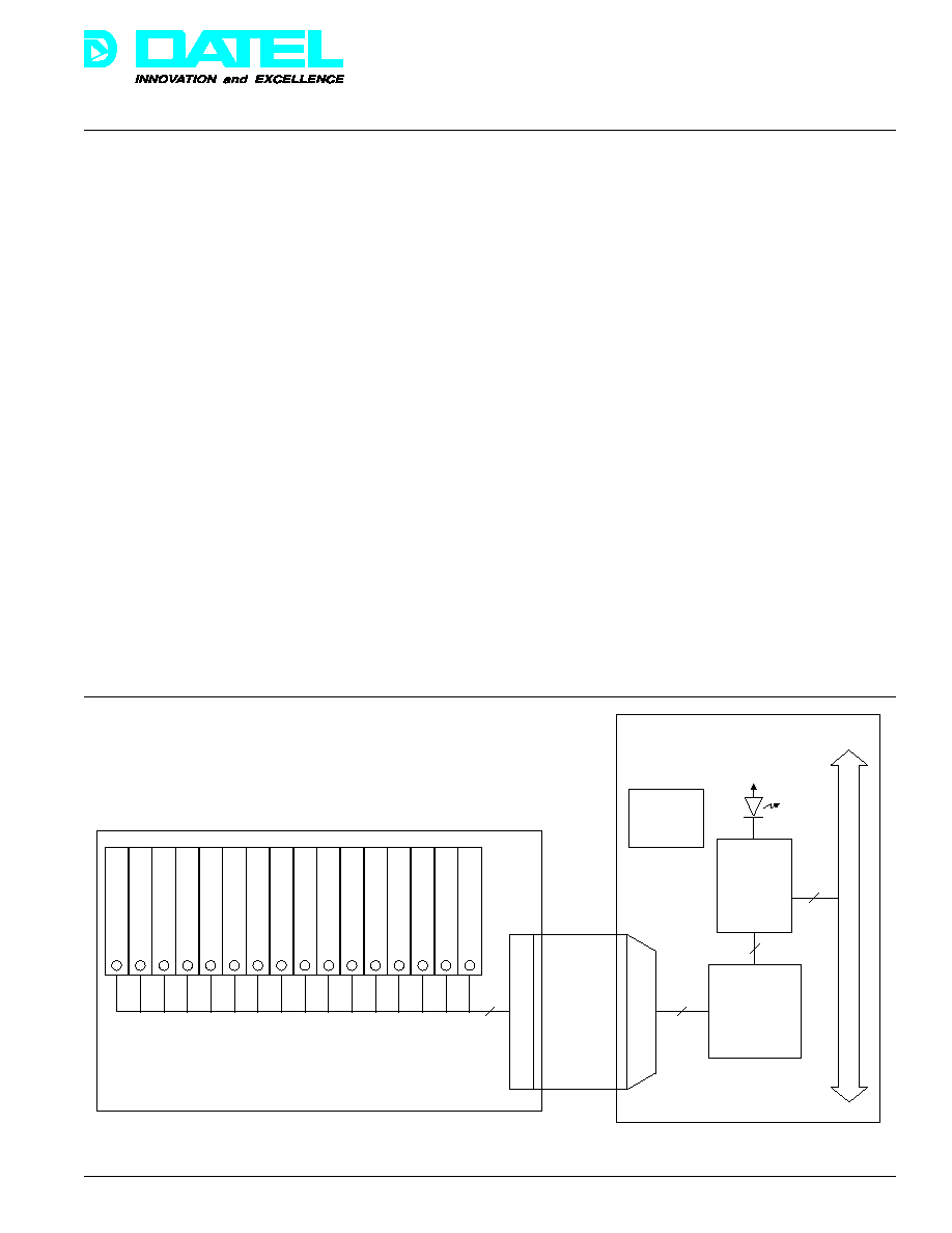
The CPCI-564 is a 16 channel input and output interface board
designed to accommodate up to 16 optically isolated externally
mounted miniature solid state I/O modules. The CPCI-564 is
easily installed in any 3U CompactPCI computer or back plane,
and the PC-G4PB16 module mounting rack can be mounted in
any 19 inch rack or DIN rail, or panel. The CPCI-564 provides
sensing and control circuitry to monitor or control the I/O modules.
It can be used with various applications including external voltage
sensing for both AC and DC, energy management, industrial
control, alarm control, and production test.
The I/O mounting boards accommodate industry standard
miniature, optically isolated, solid state I/O modules. Boards
are available for mounting 4, 8, or 16 I/O modules in any
combination of input or output. Each module rack includes a
built in fuse tester and a spare fuse. Power to the module
rack can be obtained directly from the CPCI-564 or from an
external power supply.
Figure 1. Functional Block Diagram
DATEL, Inc., Mansfield, MA 02048 (USA)
∑
Tel: (508)339-3000, (800)233-2765 Fax: (508)339-6356
∑
Email: sales@datel.com
∑
Internet: www.datel.com
PRODUCT DATA
Programmable
Logic
CPCI BUS
PCI
Controller
Front Panel
Activity Indicator
(Yellow LED Lamp)
K0
K1
K2
K3
K4
K5
K6
K7
K8
K9
K10
K11
K12
K13
K14
K15
16 I/O Module Mounting Rack
(4 and 8 I/O module mounting
racks available but not shown)
CPCI-564
50 PIN CONNECTOR
50 PIN CABLE
(CPCI-564CBL)
50 PIN CONNECTOR
DC/DC
Power
Converter
Each I/O module includes an LED status indicator, and all
output modules feature a top mounted replaceable fuse.
Modules are available in a wide variety of DC and AC input
voltage ranges. AC/DC input and AC/DC output modules can
be combined within one board. All modules offer voltage
isolation to 4000 Vrms.
Æ
Æ
CPCI-564
DATEL, Inc., Mansfield, MA 02048 (USA)
∑
Tel: (508)339-3000, (800)233-2765 Fax: (508)339-6356
∑
Email: sales@datel.com
∑
Internet: www.datel.com
Input Modules
Model
VRange
IMax
Turn-on
Turn-off
PC-G4IAC5
90-140 VAC
11 mA
20 mS
20 mS
PC-G4IAC5A
180-280 VAC
5 mA
2 mS
20 mS
PC-G4IDC5D
2.5-28 DC
30 mA
1 mS
1.5 mS
PC-G4IDC5
10-32 DC
25 mA
5 mS
5 mS
Output Modules
PC-G4OAC5
12-140 VAC
3A
0.5 Cycle 0.5 Cycle
PC-G4OAC5A
24-280 VAC
3A
0.5 Cycle 0.5 Cycle
PC-G4ODC5
3-60 VDC
3A
50 µS
50 µS
PC-G4ODC5A
5-200 VDC
1A
100 µS
750 µS
PC-G4ODC5R*
0-100 VDC
1.5A
500 µS
500 µS
Form A
PC-G4ODC5R5*
0-100 VDC
1.5A
500 µS
500 µS
Form B
I/O Modules Environmental
Isolation Voltage
4000 Vrms
Operating Temp.
≠30 to +80∞C
Storage Temp.
≠40 to +100∞C
Dimensions (inches)
1.6 H x 1.0 L x 0.4 W
CPCI-564
Front Panel Connector
50 Pin high density D sub
PCI Controller
AMCC S5920
Outline Dimensions
CPCI 3U size
Operating Temp. Range
0 to 60∞C
Storage Temp. Range
≠25 to +85∞C
Built-in Power Supply
+5V @ 1.6A (8W total)
DC/DC Converter
Isolation
1500Vdc
*Mechanical Relay
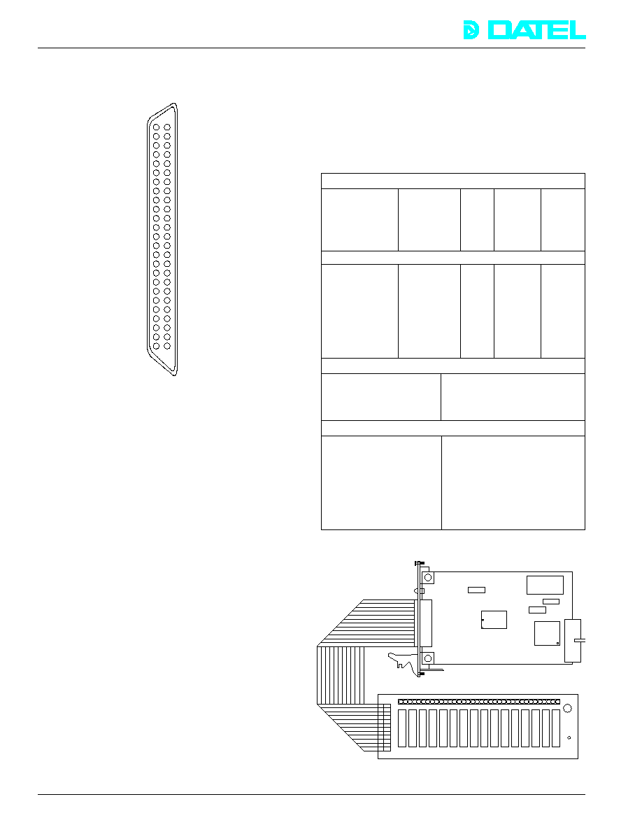
Input/Output Connector
The I/O connector for the CPCI-564 is a high density 50-pin "D"
connector and is accessible at the front of the CPCI chassis.
Figure 2. I/O Connector
Software
Windows 95/98/NT have become the platforms of choice for
many data acquisition, test, measurement, and control
applications. These feature rich, 32-bit operating systems
exploit huge amounts of memory, secure multi-threading, and
hardware plug-n-play (PnP) to provide high performing, user
friendly working environments.
CPCI-564WIN
Each CPCI-564 includes installation software for hardware
detection and initialization under Windows 95/98 and Windows
NT. The control panel provides an easy to use, point and click
graphical user interface (GUI) allowing access to relay
channel configuration, pin out, input relay monitoring, and
output relay control.
CPCI-564WINS
The CPCI-564WINS includes all the features of the
CPCI-564WIN software plus the complete source code to the
GUI application and ActiveX (Microsoft Visual Basic) and DLLs
(Visual C++), and allows you to communicate with the CPCI-564
from the familiar environment of your favorite high level language
- C/C++, Visual Basic, LabVIEW
Æ
, etc. Its standard Windows
ActiveX control facilitates custom software development of the
CPCI-564 into other applications. The source code also
contains some simple example programs in Visual Basic, Visual
50
49
48
47
46
45
44
43
42
41
40
39
38
Ground
+5 VDC
Ground
K0
Ground
K1
Ground
K2
Ground
K3
Ground
K4
Ground
24
23
22
21
20
19
18
17
16
15
14
13
37
K5
12
36
Ground
11
35
K6
10
34
Ground
9
33
K7
8
7
Ground
K12
Ground
K13
Ground
K14
Ground
K15
Ground
N/C
N/C
Ground
N/C
Ground
N/C
Ground
N/C
25 K11
Ground
32
Ground
6
Ground
31
K8
5
N/C
30
Ground
4
Ground
29
K9
3
N/C
28
Ground
2
Ground
27
K10
1
+5 VDC
26
Ground
FUNCTIONAL SPECIFICATIONS (typical at +25∞C unless noted)
C++, Quick C, and National Instruments' LabVIEW.
LabVIEW Support
Included with the CPCI-564WINS, is a tutorial on how to
implement the CPCI-564 ActiveX in a LabView VI (Virtual
Instrument) that allows complete hardware control under
LabVIEW. Also allows for the control of multiple CPCI-564s in
one system. The CPCI-564WINS includes complete functional
VI sample programs.
CR1 LED
P2
SSR Mounting Rack, PC-G4PB16
CPCI-564
(Please order separately)
U1
PCI
Controller
P1
U3
PLD
P4
FS1
DC/DC Power
Converter
P3
1
Fuse
CPCI Bus
CPCI-564CBL
Cable
Interconnections
Æ
Æ
CPCI-564
DATEL, Inc., Mansfield, MA 02048 (USA)
∑
Tel: (508)339-3000, (800)233-2765 Fax: (508)339-6356
∑
Email: sales@datel.com
∑
Internet: www.datel.com
ORDERING INFORMATION
CPCI-564
16 I/O module controller board for the CPCI bus.
CPCI-564WIN
Windows 95/98/NT software application for the CPCI-564. Includes a Windows device driver and ActiveX.
Included with CPCI-564.
CPCI-564WINS
Source code for CPCI-564WIN. Includes the source code to the GUI application, ActiveX (Microsoft Visual
Basic) and DLL sources (Visual C++), plus sample programs in C/C++, Visual Basic, and National Instruments'
LabVIEW.
CPCI-564CBL
50-pin one meter cable with connectors. Mates CPCI-564 to PC-G4PB16H.
I/O Module Mounting Racks
PC-G4PB16H
16 Module mounting rack
I/O Modules
PC-G4IAC5
90-140 VAC input module
PC-G4IAC5A
180-280 VAC input module
PC-G4IDC5D
2.5-28 VDC input module
PC-G4IDC5
10-32 VDC input module
PC-G4OAC5
12-140 VAC output module
PC-G4OAC5A
24-280 VAC output module
PC-G4ODC5
3-60 VDC output module
PC-G4ODC5A
5-200 VDC output module
PC-G4ODC5R
0-100 VDC Form A output module
PC-G4ODC5R5
0-100 VDC Form B output module
LabVIEW is a National Instruments trademark
Windows is a Microsoft Corporation trademark
CompactPCI is a PCI Industrial Computer Manufacturers Group trademark
DATEL is DATEL, Inc. trademark
Rev. C 12/99
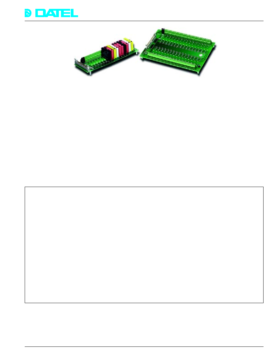
DATEL offers the industry standard G4 series of base boards,
solid state and mechanical relay modules, as well as some
custom designed mechanical relay boards and screw terminal
panels. Direct connect cabling is also available.
PC-G4PB32DEC, PC-G4PB16
Both the G4PB32DEC and G4PB16 mounting panels
accommodate miniature, optically-isolated, solid state I/O
modules. The G4PB32DEC holds up to 32 modules
configured as 16 input and 16 output. The G4PB16 is
configured to hold 16 modules, all either input or output. Each
G4 series module rack includes a built in fuse tester and
spare fuse. Power and interface to external devices is
accomplished via screw terminals.
G4 Series Solid State I/O Modules
Each G4 module offers high-density single channel packaging.
All modules include an LED status indicator, and all digital
output modules feature a top mounted replaceable fuse.
Modules are available in a wide variety of DC and AC voltage
ranges. DC input modules and AC input modules can be
combined within one board as can DC output and AC output
modules within one board.