 | –≠–ª–µ–∫—Ç—Ä–æ–Ω–Ω—ã–π –∫–æ–º–ø–æ–Ω–µ–Ω—Ç: DCA5-20PC | –°–∫–∞—á–∞—Ç—å:  PDF PDF  ZIP ZIP |
DATEL, Inc., Mansfi eld, MA 02048 (USA)
∑
Tel: (508)339-3000, (800)233-2765 Fax: (508)339-6356
∑
E≠mail: sales@datel.com
∑
Internet: www.datel.com
DCA5-20PC Series
50mV & 100mV Input,
LED Display, Subminiature
DC Ammeters
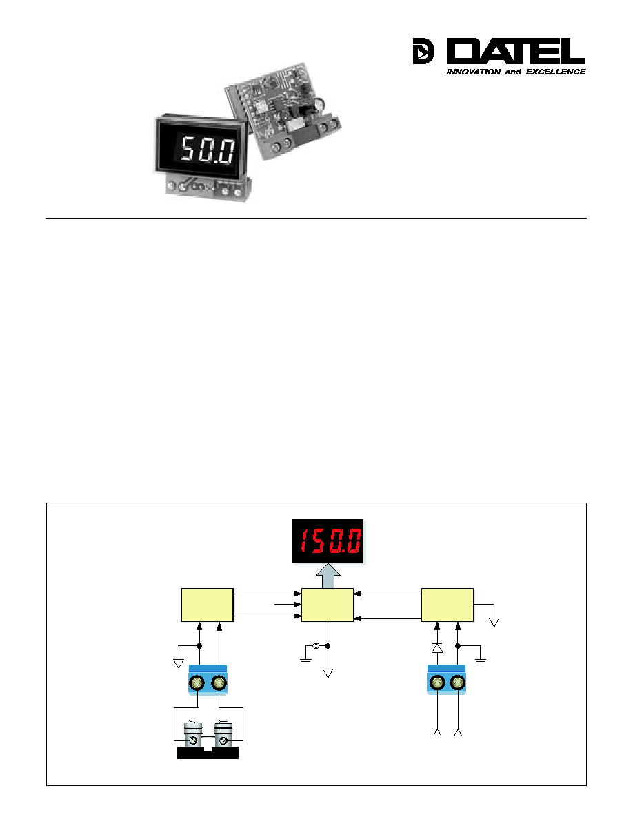
Figure 1. DCA5-20PC Series Simplifi ed Schematic
Features
Æ
Æ
∑
Scales and displays the output of 5A to 2000A,
50mV & 100mV shunts
∑
Completely self-contained ≠ no additional
components required
∑
Wide power supply inputs: 5 to 40Vdc for
12V/24V/28V applications
∑
48V option for telecom supplies
∑
Isolated-supply models for high-side shunts
∑
Large, easy-to-read LED display with 0.37"
(9.4mm) high digits
∑
Available in red, blue or green LED displays
∑
Subminiature 1.38" x 0.88" package with
screw-style terminal blocks
∑
Factory calibrated to ±0.1% accuracy;
Reverse-polarity protection
∑
Over 50 models available
∑
Digital upgrade for analog meters
DATEL's new DCA5-20PC Series dc ammeters are specifi cally designed to display
the output of all popular 50mV and 100mV dc-shunts. 25 input ranges provide for
precision measurement of dc currents from 1.000A to 2000A. With the exception of
an external shunt, the unit is 100% self-contained ≠ no calibration or user-supplied
components are required. Available LED-display colors include brilliant blue, bright green,
and standard red. Three power supply options accommodate all popular dc-supply
voltages from 5V to 75Vdc, making these ammeters perfect for automotive, industrial,
telecom, and marine applications!
DCA5-20PC Series ammeters are housed in 1.38" x 0.88" (35mm x 22mm) rugged
packages that feature a large, 0.37"/9.4mm high, LED display. However, display visibility
is not compromised in any way: the display can be easily read at distances up to 15
feet (5 meters). All input and power supply connections are made by way of two screw-
style terminal blocks. For added fl exibility, computer-style jumpers are provided for range-
specifi c decimal point assignments. And, to ensure trouble free installation, all models
include reverse-polarity protected power supply inputs.
Two input confi gurations are offered: grounded shunt ("low-side"), 5-40V-powered,
red LED models for cost-sensitive applications, and 8-36V isolated-supply models that
accept high-side or fl oating shunts. Isolated-supply models are available in a choice
of red, green, or blue LEDs. Since many dc ammeters are used in battery backup
applications, power consumption for 8-36V models is typically 1 Watt, and 75mW for
5-40V models.
Miniature size, wide supply inputs, and no-hassles installation make DCA5-20PC
Series ammeters the ideal choice for all your 50 and 100mV shunt ammeter-applications.
Order online at www.datel.com
A/D
CONVERTER
LED DISPLAY
INPUT
AMPLIFIER
EXTERNAL DC SUPPLY
POWER
CONVERTER
1
2
TB1
CAL
≠5V
+5V
TB2
POWER
GROUND
SIGNAL
GROUND
EXTERNAL
50 or 100mV SHUNT
Not included on all models
Open on isolated power models
≠V (GND)
+V
+IN
≠
≠IN
≠
+
+
*
*
**
**
1
2
1
2
5 0 M V a n d 1 0 0 M V I N P U T , L E D D I S P L A Y , D C A M M E T E R S
DCA5-20PC Series
2
DATEL, Inc., Mansfi eld, MA 02048 (USA)
∑
Tel: (508)339-3000, (800)233-2765 Fax: (508)339-6356
∑
E≠mail: sales@datel.com
∑
Internet: www.datel.com
A full-scale input voltage of 50.00mV is used to calibrate all models for their
designated measurement range. The ammeter's rear calibration potentiometer
compensates for full-scale input variations up to ±1% (49.5 to 50.5mV).
Measuring positive and negative currents (bipolar operation): In applications
where both positive and negative currents must be measured, DATEL recom-
mends using `-DC4' 8-36V isolated supply models. Negative current fl ow is
denoted by the illumination of the display's negative (-) sign; the absence of
a negative sign implies positive current fl ow. Contact DATEL if you have any
questions regarding bipolar operation of DCA5-20PC ammeters.
On non-isolated `-DC1' models, continuous application of single-ended ±400mV
inputs will not damage the ammeter. Single-ended inputs are defi ned as those
whose TB1-1 (-IN) potential is within ±0.1V of the potential on TB2-2 (-V). For
all models, the application of short-duration (5 seconds max.) ±1V inputs will not
damage the ammeter.
Breakdown (isolation) voltage applies only to `-DC4' isolated-power models.
Breakdown voltage is tested with TB1-1 tied to TB1-2 (-IN shorted to +IN) and
TB2-1 tied to TB2-2 (+V shorted to -V). 500Vdc is then applied between the two
shorted terminal-block pairs; the max. allowable leakage current is 5uA.
Zero reading is measured with TB1-1 (-IN) shorted to TB1-2 (+IN).
Power supply currents noted are measured with the 50mV shunt input (TB1) at
zero volts (display reads "000") and one decimal point enabled.
Each model's full-scale display reading with a 50.0mV input is designated by
the fi rst X in the DCA5-20PC-X-XXX model number structure. Decimal point
selection (DP1, DP2, DP3, or none) is performed by the user to suit desired
amperage range. Input ranges -1, -2, -3, -4, -7, -8 and -9 can accommodate
100mV shunts. For these ranges, the indicated 50mV reading is doubled
when a 100mV input is applied.
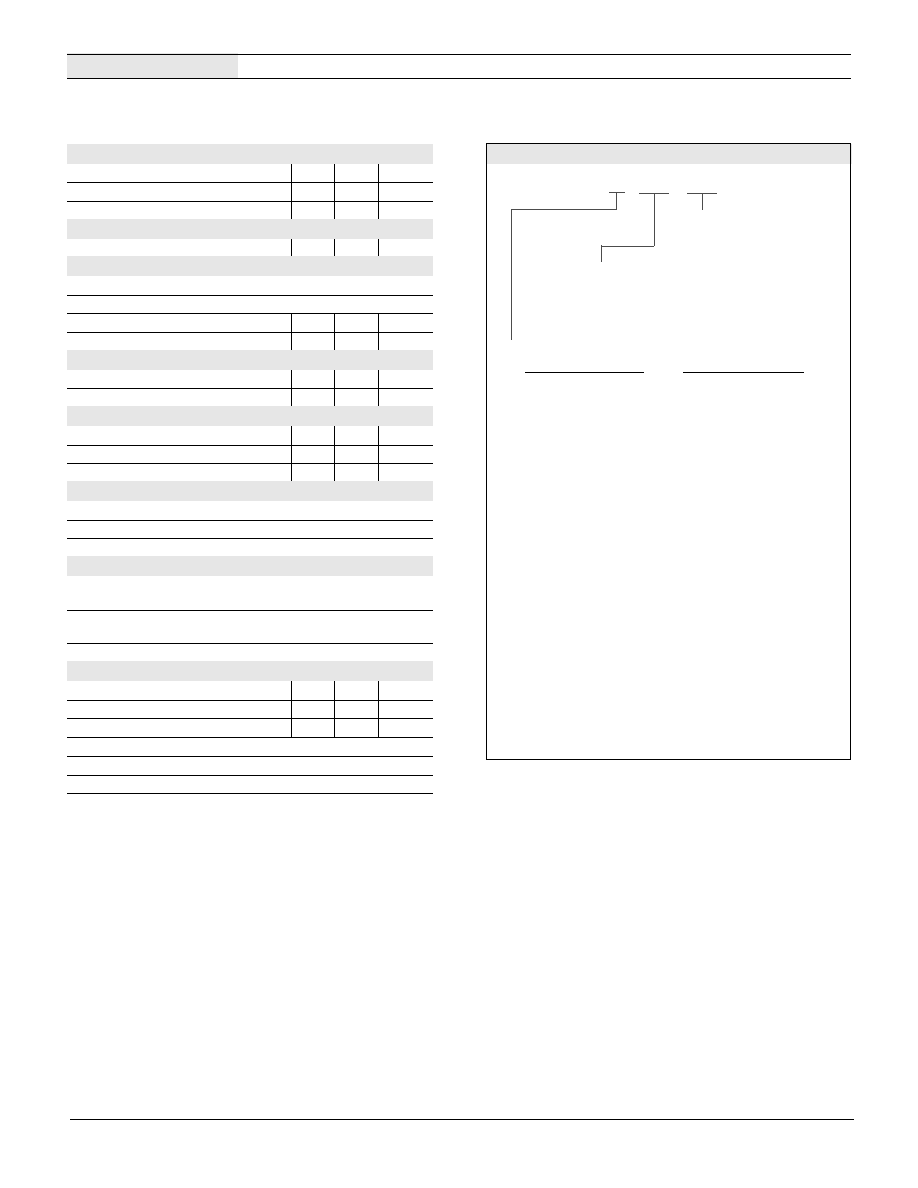
Performance/Functional Specifi cations
Typical at T
A
= +25∞C, unless otherwise noted.
Input Range:
50mV Shunt Readings
*
100mV
Shunt
Readings
*
1 = 5.00A/50.0A/500A
10.00A/100.0A/1000A
2 = 1.000A/10.00A/100.0A/1000A
1.999A/19.99A/199.9A/1999A
3 = 30.0A/300A
60.0A/600A
4 = 75.0A/750A
15.00A/150.0A/1500A
5 = 15.00A/150.0A/1500A
N/A
6 = 1.999A/19.99A/199.9A/1999A
N/A
7 = 25.0A/250A
5.00A/50.0A/500A
8 = 400A
80.0A/800A
9 = 600A
120.0A/1200A
10 = 80.0A/800A
N/A
11 = 1200A
N/A
Ordering Information
DCA5-20PC - 1 - DC1 - R L
Order on-line at www.datel.com
Power Supply:
DC1 = 5-40Vdc, non-isolated power
(available with red LEDs only)
DC4 = 8-36Vdc, isolated power
(available with red, green, or blue LEDs)
LED Color:
BS = Super Blue
GS = Standard Green
RL = Low-Power Red
Accessories:
DMS-20-CP Panel
Cutout
Punch
39-1734101 50A/50mV
Shunt
39-1734102 5A/50mV
Shunt
39-1734103 20A/50mV
Shunt
39-1734104 100A/50mV
Shunt
39-1734106 150A/50mV
Shunt
39-1734107 200A/50mV
Shunt
Input (TB1)
Min.
Typ. Max. Units
Full Scale Input
49.5
50 50.5 mV
Overvoltage Rating
±400
≠ ≠ mV
Input Impedance
≠
1K ≠ Ohms
Input to Supply Isolation
DCA5-20PC-X-DC4-XX models only
500
≠ ≠ Vdc
Performance
Sampling Rate
2.5 samples per second
Accuracy
±0.15%FS
Temperature Drift (0 to 60∫C)
≠
±0.2 ±0.4 Cnts/∫C
Zero-Current Reading
-001
000 001 Cnts
Power Supply Voltage (TB2)
DCA5-20PC-X-DC1-XX
+5.0
≠ +40 Vdc
DCA5-20PC-X-DC4-XX
+8
≠ +36 Vdc
Power Supply Current
DCA5-20PC-X-DC1-XX (@5-40V)
≠
10 15 mAdc
DCA5-20PC-X-DC4-XX (@8V)
≠
100 150 mAdc
DCA5-20PC-X-DC4-XX (@36V)
≠
25 40 mAdc
TB1& TB2 Terminal Blocks
Wire Size
16-22AWG, solid or stranded
Insulation Strip Length
0.250 inches
Screw Tightening Torque
3.6 pound-inches (0.4Nm)
Display
Display Type and Size
3Ω Digit, 0.37"/9.4mm high, red,
blue, or green LED
Overrange Indication
"1___" for positive input
"≠1___" for negative input
Display Reading/Decimal Point
Model dependent
Physical/Environmental
Operating Temperature
0
≠ +60 ∫C
Storage Temperature
≠40
≠ +75 ∫C
Humidity (non-condensing)
0
≠ 85 %
Case Material
Polycarbonate
Dimensions
1.38"W x 0.88" x 1.0" nominal
Weight (all models)
0.6 Ounces (17 grams) nominal
39-1734108 300A/50mV
Shunt
39-1734109 500A/50mV
Shunt
39-1734111 800A/50mV
Shunt
39-1734112 1000A/50mV
Shunt
39-1734113 1200A/50mV
Shunt
39-1734119 10A/100mV
Shunt
39-1734120 100A/100mV
Shunt
*
With respective decimal point user enabled. See technical note 7.
A DMS-BZL4 bezel assembly with sealing gasket is
supplied with each ammeter

5 0 M V a n d 1 0 0 M V I N P U T , L E D D I S P L A Y , D C A M M E T E R S
DCA5-20PC Series
3
DATEL, Inc., Mansfi eld, MA 02048 (USA)
∑
Tel: (508)339-3000, (800)233-2765 Fax: (508)339-6356
∑
E≠mail: sales@datel.com
∑
Internet: www.datel.com
Technical Notes
Figure 2. Low-Side Shunt Connections for "-DC1"
5-40Vdc Non-Isolated Supply Models
To ensure safe and reliable operation, DCA5-20PC dc ammeters
must only be installed and serviced by qualifi ed technical person-
nel. DC ammeter applications can expose a user to potentially
lethal currents and voltages. Power and signal connections must
be made with all associated power sources de-energized. Contact
DATEL if you have any questions regarding the installation or
operation of any of our digital instruments.
1. Calibration: DCA5-20PC ammeters are designed to operate with
50mV and 100mV dc shunts whose rated accuracy is ±0.25%, or
better. The output of less accurate shunts may fall outside the amme-
ter's ±1% calibration adjustment range. Under normal indoor operating
conditions, periodic recalibration of DCA5-20PC ammeters is not nec-
essary. The calibration potentiometer, located on the back of the
ammeter, is a æ turn type; do not force its adjustment screw past the
two end stops.
If user calibration is deemed necessary, it must be performed by
qualifi ed personnel. Calibration is performed by applying a precision
50.00mVdc or 100mVdc (model specifi c, see ordering guide) signal to
TB1, observing correct polarity. Then, using an insulated slotted tool,
adjust the calibration potentiometer until the correct display reading is
achieved. Contact DATEL if additional information is required regarding
calibration or setup of DCA5-20PC ammeters.
2. Wiring and Fusing: Power supply (TB2) and input (TB1) wiring must
be rated for the electrical and environmental conditions under which
the ammeters will be operated. They must also comply with any regula-
tory or application-mandated requirements pertaining to the user's
installation. Connections to DCA5-20PC ammeters must be made with
all power sources de-energized. Refer to the Functional Specifi cations
section for TB1 and TB2 wire gauge information.
DCA5-20PC ammeters' shunt (TB1) and power supply inputs (TB2)
are not internally fused. Therefore, the supply wires connected to the
meter and the load should be fused according to the maximum current
rating (or lower) of the wire gauge used, in accordance with applicable
regulatory codes. Insulation should be stripped to within +/-10% of the
stated dimensions. All wires must be inserted into the terminal block
openings such that the screw terminal does not pinch any insulation.
TB2 is to be used solely for powering the meter's internal circuitry; it
must not be used to supply current to an external load or auxiliary
device.
3. Terminal Block Torque Ratings: It is important to tighten TB1's and
TB2's screw-terminals to their rated torque specifi cations of 3.6 pound-
inches (0.4Nm). Proper tightening will minimize losses and ensure
reliable operation.
4. High-Side versus Low-Side Shunts: Incorrect shunt connections
are one of the most common problems encountered when applying
digital dc-ammeters. Incorrect shunt connections can cause permanent
damage to the ammeter and/or its associated equipment.
Low-Side Shunts: Applications that employ a single power supply to
power both the load and the ammeter, and the external shunt is located
in the negative side of the supply (commonly referred to as "low side" or
"grounded shunt") should use `-DC1' non-isolated power DCA5-20PC
Series ammeters. Figures 2 and 3 depict typical low-side shunt con-
Figure 3. Low-Side Shunt Connections for "-DC1" Models Modifi ed for
36-75Vdc Non-Isolated Power (See Technical Note 5)
≠IN
≠
+IN
+
≠V
+V
LOAD
50mV SHUNT
DC SUPPLY
5-40Vdc
POWER
GROUND
(0Vdc)
LOAD CURRENT
J3 MUST BE INSTALLED
(FACTORY SETTING) FOR
5-40Vdc SUPPLIES
J1 AND J2 POSITIONS
DEPEND ON INPUT RANGE
DCA5-20PC-X-DC1-XX
SHUNT MUST
BE IN LOW SIDE
1
1
1
2
2
CAL
TB1
TB2
J1 J2
J3
1
1
2
2
3
1
2
1
1
1
2
2
CAL
TB1
TB2
J1 J2
J3
1
1
2
2
3
1
2
≠IN
≠
+IN
+
≠V
+V
LOAD
50mV SHUNT
DC SUPPLY
36-75Vdc
POWER
GROUND
(0Vdc)
LOAD CURRENT
REMOVE J3
FOR 36-75Vdc
SUPPLIES
SHUNT MUST
BE IN LOW SIDE
DCA5-20PC-X-DC1-XX

5 0 M V a n d 1 0 0 M V I N P U T , L E D D I S P L A Y , D C A M M E T E R S
DCA5-20PC Series
4
DATEL, Inc., Mansfi eld, MA 02048 (USA)
∑
Tel: (508)339-3000, (800)233-2765 Fax: (508)339-6356
∑
E≠mail: sales@datel.com
∑
Internet: www.datel.com
Figure 4. High-Side Shunt Connections for "-DC4"
8-40Vdc Isolated-Power Models
Figure 5. Using "-DC4" Isolated-Power Models to Maintain Isolation
Between Two Power Supplies
also be used in applications where one supply powers the ammeter
and a second supply powers the load, but the two supply grounds
cannot be tied together. `-DC4' isolated-supply models include a built-in
dc/dc converter to provide a minimum of 500Vdc isolation between the
shunt (TB1) and power supply inputs (TB2).
5. Operation With 36 to 75Vdc Power: As shipped, all `-DC1' models'
rated operating supply range is +5 to +40Vdc. However, `-DC1' models
can be user confi gured for 36 to 75Vdc operation by removing (open-
ing) jumper J3. Please note that this user modifi cation can only be
performed on `-DC1 power models. Also, all `-DC1' models ≠ including
those that have been modifi ed for 36-75Vdc operation ≠ can only be
connected in low-side, grounded-shunt applications. See Figure 3 for
detailed wiring information. Any reconfi guration of J3 must be made
prior to connecting the power supply and shunt to the ammeter.
6. Replacing Analog Panel Meters: DCA5-20PC ammeters can be
used as replacements for analog panel meters that are driven by 50
or 100mV shunts, if a suitable dc voltage is available for powering
the ammeter. In retrofi t applications, it is extremely important to deter-
mine the shunt's electrical confi guration (i.e., high or low side). If
any doubt exists as to the shunt's location, use only `-DC4' isolated-
supply models. Rewiring must be performed with all power sources
de-energized.
7. Decimal Point Selection: As shown in the Ordering Information
guide, DCA5-20PC ammeters are multiple input-range devices. For
example, with a 50mV input, DCA5-20PC-1-DC1 models can be con-
fi gured to display "5.00", "50.0, or "500" Amps by simply removing or
relocating decimal-point-selector jumper J2 (see Figure 6). Decimal
points serve as placeholders only; they have no affect on displayed
accuracy or resolution. If jumper J2 is not available, solder gaps SG1,
SG2, or SG3 can be used to select DP1 ("1.XXX"), DP2 ("1X.XX"), or
DP3 ("1XX.X"), respectively.
nections.
High-Side Shunts: `-DC4' isolated-power ammeters must be used in
all applications that employ a single power supply to power both the
load and the ammeter and the shunt is located in the high side (posi-
tive terminal) of the supply. Figures 4 and 5 depict typical high-side
shunt connections. As shown in Figure 5, isolated-power models can
Figure 6. Decimal Point Selection Using J2 and J1
(Applies to All Models)
1
1
1
2
2
CAL
TB1
TB2
J3 J1 J2
1
1
2
2
3
M1
≠IN
≠
+IN
+
≠V
+V
LOAD
50mV SHUNT
DC SUPPLY
8-36Vdc
POWER
GROUND
(0Vdc)
LOAD CURRENT
1
1
1
2
2
CAL
TB1
TB2
J1
J3
J2
1
1
2
2
3
M1
≠IN
≠
≠
+IN
+
+
≠V
+V
50mV SHUNT
LOAD CURRENT
DC SUPPLY #1
8-36Vdc
DC SUPPLY
#2
LOAD
SHUNT CAN BE IN
LOW OR HIGH SIDE
1
1
1
2
2
CAL
TB1
TB2
J1 J2
J3
1
1
2
2
3
1
2
J2 CONFIGURATION
DP2 OFF
DP3 OFF
DP3 ON
(1XX.X)
DP2 ON
(1X.XX)
SG3
SG2
SG1
1
2
3
1
2
3
1
2
3
DP1 OFF
1
2
DP1 ON
(1.XXX)
1
2
J1 CONFIGURATION
ALL MODELS

5 0 M V a n d 1 0 0 M V I N P U T , L E D D I S P L A Y , D C A M M E T E R S
DCA5-20PC Series
5
DATEL, Inc., Mansfi eld, MA 02048 (USA)
∑
Tel: (508)339-3000, (800)233-2765 Fax: (508)339-6356
∑
E≠mail: sales@datel.com
∑
Internet: www.datel.com
Model
100mV Shunt Readings
DCA5-20PC-1
10.00A/100.0A/1000A
DCA5-20PC-2
1.999A/19.99A/199.9A/1999A
DCA5-20PC-3
60.0A/600A
DCA5-20PC-4
150.0A/1500A
DCA5-20PC-7
50.0A/500A
DCA5-20PC-8
800A
DCA5-20PC-9 1200A
Step 1.
Step 2.
Step 3.
Step 4.
Table 1. 100mV Shunt Readings
*
Panel Installation
8. Operation With 100mV Shunts: Many DCA5-20PC Series ammeters
can also operate with 100mV shunts. This is due to the fact that
when they are driven by a 100mV input, the display readings are
double those of a 50mV input. However, a 50mV shunt cannot be used
in a 100mV application because its maximum current rating will be
exceeded.
For our customer's convenience, DATEL offers a series of 50mV and
100mV chassis-mount dc shunts that can be used with DCA5-20PC
ammeters. Part numbers for accessory shunts can be found in the
Ordering Information section. A data sheet describing these shunts is
available at www.datel.com.
Table 1 indicates the obtainable readings of the seven DCA5-20PC
models that can be operated with 100mV shunts. Be sure to enable the
correct decimal point (see decimal point selection instructions).
9. Noisy Power Supplies: Some power supplies contain high-frequency
switching devices that may conduct and/or radiate signifi cant noise
onto the low-level 50/100mV shunt signal. Even though the DCA5-
20PC incorporates built-in fi ltering at its shunt input, some portion of
this noise may be amplifi ed and subsequently measured by the DCA5-
20PC's sensitive circuitry. The amplifi ed noise introduces errors that
All connections and modifi cations must be made after the ammeter is
securely attached to the panel, with all load and supply voltages de-
energized (off).
The installed wire-positions should be such that minimal forces are applied to
TB1, TB2, and the ammeter itself. In high-vibration environments, the use of
wiring strain-reliefs is recommended.
To insure a secure panel-mount installation, DATEL recommends using the
DMS-BZL4 (with sealing gasket) bezel assembly supplied with each ammeter.
are particularly noticeable at zero load current (i.e., the ammeter may
not display a relatively steady "000" reading).
Connecting an external, unpolarized capacitor across TB1's "+" and
"≠" inputs, and/or across the shunt's 50mV output terminals, can help
reduce noise-related display errors. In certain situations, the use of
twisted pair or shield wiring may be required. As a general rule, avoid
using excessively long leads between the ammeter and the shunt.
Figure 7. Panel Installation
See the Mechanical Specifi cations section for detailed panel cutout and
ammeter dimensions.
Following the four-step sequence shown in Figure 7 below, being careful
not to apply excessive force or twisting motions, insert the ammeter into the
panel opening. When using the DMS-BZL4's sealing gasket, make sure it
is positioned between the ammeter's fl ange and the panel's front surface.
Be sure to use and securely tighten all four screws supplied with the bezel
assembly.
PANEL
PANEL
PANEL
2
1
PANEL
3
4
BEZEL
GASKET
(optional)
*
With respective decimal point enabled

DATEL, Inc. 11 Cabot Boulevard, Mansfi eld, MA 02048-1151
Tel: (508) 339-3000 (800) 233-2765 Fax: (508) 339-6356
Internet: www.datel.com Email: sales@datel.com
DATEL (UK) LTD. Tadley, England Tel: (01256)-880444
DATEL S.A.R.L. Montigny Le Bretonneux, France Tel: 01-34-60-01-01
DATEL GmbH M¸nchen, Germany Tel: 89-544334-0
DATEL KK Tokyo, Japan Tel: 3-3779-1031, Osaka Tel: 6-6354-2025
DATEL makes no representation that the use of its products in the circuits described herein, or the use of other technical information contained herein, will not infringe upon existing or future patent rights. The descriptions contained herein do
not imply the granting of licenses to make, use, or sell equipment constructed in accordance therewith. Specifi cations are subject to change without notice. The DATEL logo is a registered DATEL, Inc. trademark.
Æ
Æ
DCA5-20PC Series
5 0 M V a n d 1 0 0 M V I N P U T , L E D D I S P L A Y , D C A M M E T E R S
DS-0517
A 03/03
Mechanical Specifi cations
ISO 9001
Registered
#2-56 INSERT
0.156 (3.96) DEEP
FRONT VIEW
1.280
(32.51)
0.187
(4.75)
DMS-BZL4 BEZEL
RECOMMENDED DRILL AND PANEL CUTOUT DIMENSIONS
1.826 (46.38)
0.838
(21.29)
1.626 (41.30)
1.07
(27.18)
INTERNAL CORNER RADII:
0.032 (0.81) MAX.
0.093 (2.362) DIAMETER (4 REQUIRED)
ONLY WHEN USING SUPPLIED BEZEL ASSEMBLY
0.116 (2.95)
1.336 (33.93)
0.145 (3.68)
MECHANICAL DIMENSIONS: Inches (mm)
TOLERANCES: 2 PL DEC ±0.02 (±0.51)
3 PL DEC ±0.010 (±0.254)
1
1
1
2
2
CAL
TB1
TB2
J1 J2
J3
1
1
2
2
3
1
2
SG3
SG2
SG1
0.80
(20.3)
0.88
(22.4)
1.30
(33.0)
0.040
(1.02)
1.00
(25.4)
0.475
(12.1)
0.040
(1.02)
1.38
(35.1)
1.42
(36.1)
FRONT VIEW
BACK VIEW
≠IN
DP2
DP1
DP3
+IN
+V ≠V