
DATEL, Inc., Mansfield, MA 02048 (USA)
∑
Tel: (508)339-3000, (800)233-2765 Fax: (508)339-6356
∑
E-mail: sales@datel.com
∑
Internet: www.datel.com
DMS-30LCDA-4/20 Series
Loop-Powered, 1.8V Drop,
4-20mA Process Monitors
with Full-Size LCD-Displays
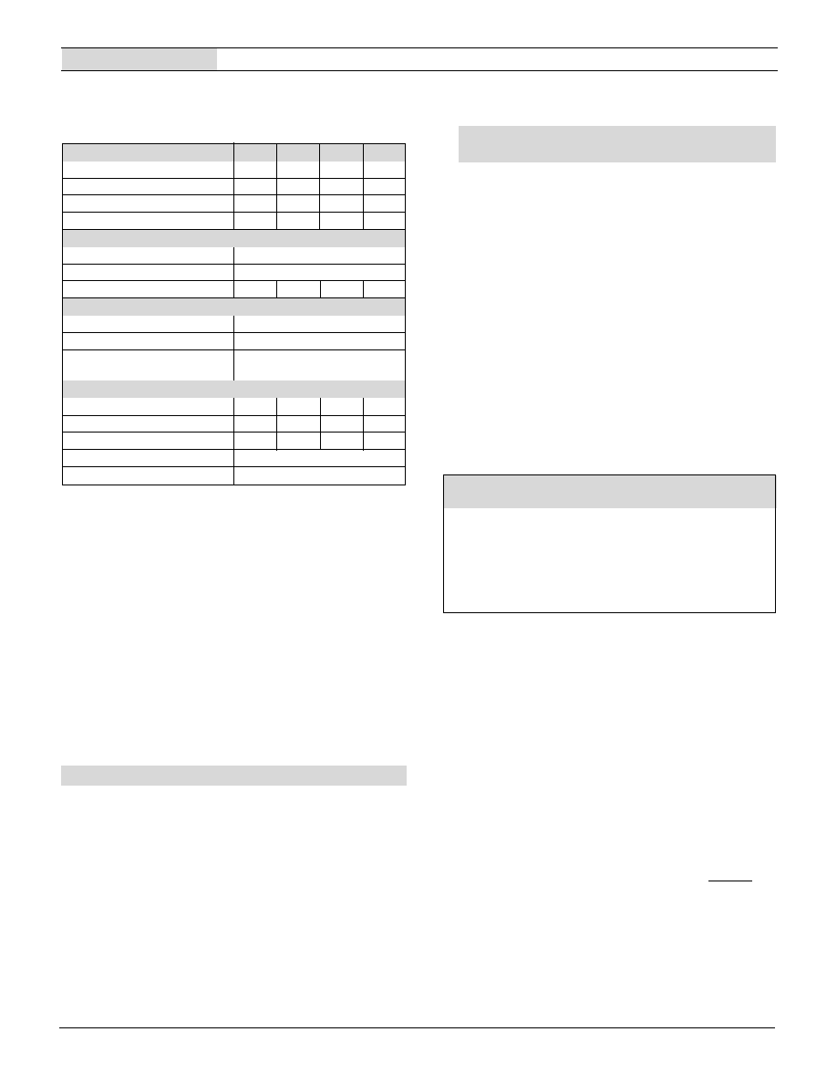
Figure 1. DMS-30LCDA-4 / 20 Simplified Schematic
Features
Actual Size
Æ
Æ
∑
Super-low loop drop: 1.8V typical, 2.0V max.
∑
Self-powered 2-wire operation; no separate
supply required
∑
Unipolar, Bipolar, Positive, and Inverse
Reading Models
∑
Improved-performance replacement for
DMS-30LCD-4/20S
∑
Subminiature package; Less than 0.90"
behind-the-panel depth
∑
Large, 0.40"/10.2mm high, sunlight-viewable
LCD display
∑
Non-interacting gain (span) and offset (zero)
20-turn potentiometers
∑
DIP-switch selectable range and decimal points
∑
Hundreds of different input-current/readout
combinations
∑
Vibration-resistant package; reliable
screw-terminal input connections
DATEL's new DMS-30LCDA-4/20 Series' 1.8V nominal loop-drop is the lowest of any
comparably priced, 4-20mA input, 3Ω-digit process monitors with full-size LCD displays.
This super-low loop-drop guarantees a maximum burden of no more than 100 Ohms! And
because it's loop-powered, all operating power is derived directly from the loop current
itself; no separate power source is required! Their floating 2-wire design allows DMS-
30LCDA-4/20 Series process monitors to be connected anywhere in the current loop.
All decimal point and range-change selections are made via an eight-position DIP
switch which features vibration-resistant, gold-plated contacts--there are no cumber-
some jumpers or solder gaps to contend with. Both gain (span) and offset (zero)
adjustments are performed using 20-turn, non-interacting potentiometers. Four different
models accommodate unipolar, bipolar, positive, and inverse display-reading applications.
The DMS-30LCDA-4/20 Series' DIP switch and adjustment potentiometers can accommo-
date literally hundreds of different input-current/output-reading combinations.
DMS-30LCDA-4/20 Series' subminiature package houses a large, 0.40"/10.2mm, high-
contrast LCD display that can be read in virtually all lighting conditions--including full
sunlight! The two connections to the external loop are made via a reliable screw-type
terminal block. For environmentally demanding applications, an optional panel-mount bezel
assembly, featuring screw fasteners and a rubber gasket, provides excellent resistance
to dust and moisture. All these outstanding features combine to make the new DMS-
30LCDA-4/20 Series ideal for all your 4-20mA process-monitoring instrumentation needs.
3 New Models!
Reduced Loop Drop
Order on-line at www.datel.com
3 Ω D I G I T A / D
C O N V E R T E R
D C / D C
C O N V E R T E R
B A N D - G A P
R E . E R E N C E
C I R C U I T
D I P S W I T C H E S
Z E R O
A D J U S T
G A I N
A D J U S T
1
2
3
C U R R E N T T O
V O L T A G E
C O N V E R T E R
+ 5 V
5 V
D P 3
D P 2
D P 1
R 3
R 7
1
2
T B 1
L O O P I N P U T
+
4
O N
O N
O N
5
8
7
6
5
4
3
2
1
D A T A
4
5
Operating and Setup Instructions
Performance/Functional Specifications
Typical at T
A
= +25∞C, unless otherwise noted.
DMS-30LCDA-4/20
3 Ω D I G I T , L C D D I S P L A Y , 4 - 2 0 m A L O O P - P O W E R E D M E T E R S
The DMS-30LCDA-4/20 can withstand continuous overcurrents, including
those resulting from accidental reverse-polarity connections, up to ±40mA
without sustaining any damage.
Because DATEL's DMS Series loop-powered process monitors employ
active circuitry to convert the loop current into a voltage, their effective
series impedance (loop burden) varies in a manner that maintains the loop
voltage drop relatively constant over the full 4-to-20mA current range. Listed
burden specification applies at 20mA.
When looking up DIP-switch settings in the Tables and the desired display
readings can be achieved with either of two different settings, using the
higher setting number will usually result in less sensitive offset (R3) and
span (R7) adjustments. Please keep in mind that the DMS-30LCDA
standard meter from which the DMS-30LCDA-4/20 is derived has an
accuracy specification of ±2 counts (max.). Thus, it may not always be
possible to obtain the exact desired display reading.
DMS-30LCDA-4/20S**
Unipolar reading, loop-powered LCD meter
DMS-30LCDA-4/20B
Bipolar reading, loop-powered LCD meter
DMS-30LCDA-4/20P
Positive reading, loop-powered LCD meter
DMS-30LCDA-4/20I
Inverse reading, loop-powered LCD meter
DMS-BZL1
Bezel assembly
DMS-BZL2
Bezel assembly with sealing gasket
DMS-30-CP
Panel cutout punch
DMS-PS4-CM
+24V/0.45A ac/dc power supply module
DMS-PS7-CM
+24V/0.7A ac/dc power supply module
Ordering Information
** Replaces obsolete DMS-30LCD-4/20S model
A panel-mount retaining clip is supplied with each model.
Current Loop Input
Min.
Typ.
Max.
Units
Full Scale Input Range
+3.8
--
+20.4
mA
Loop Burden
--
80
100
Voltage Drop
--
1.8
2.0
Volts
Overcurrent Protection
--
--
±40
mA
Performance
Sampling Rate
2.5 readings per second
Accuracy (1 minute warm-up)
±0.05%FS ±1 Count
Temperature Drift (0 to +60∞C)
--
±0.15
±0.3
Cnts/∞C
Display
Display Type and Size
3Ω digit, 0.4"/10.2mm reflective LCD
Polarity Indication
"≠" for negative readings
Overrange Indication
"≠1_ _ _ " for negative inputs
"1_ _ _ " for positive inputs
Physical/Environmental
Operating Temperature
0
--
+60
∞ C
Storage Temperature
≠20
--
+75
∞ C
Humidity (Non-condensing)
0
--
85
%
Case Material
Polycarbonate
Weight
0.75 ounces (21 grams)
Order on-line at www.datel.com
The new DMS-30LCDA-4/20S unipolar-reading model has provisions to
accommodate all the display ranges of the obsolete DMS-30LCD-4/20S.
The "Old Display Readings" column in Table 1 is taken directly from the
DMS-30LCD-4/20S datasheet. Table 1 is provided as a guide for
determining equivalent DMS-30LCDA-4/20S DIP-switch settings in
upgrading existing applications.
Applications that had the obsolete DMS-30LCD-4/20S setup for `bipolar'
operation should now use the new DMS-30LCDA-4/20S model configured
per Table 1. Bipolar applications are those where a 4mA input displays a
negative number, a 12mA input displays "000", and a 20mA input displays
a positive number (for example, "-100", "000" and "100").
Applications that had the obsolete DMS-30LCD-4/20S setup for `unipolar'
operation should now use the new DMS-30LCDA-4/20S configured per
Table 2. Unipolar applications are those where a 4mA input displays "000"
and a 20mA input displays a higher positive number.
Important Instructions for Users of Obsolete
DMS-30LCD-4/20S Meters
Old Display Reading
New DMS-30LCDA-4/20S DIP Switch Setting
4mA
20mA
SW1
SW2
SW3
SW4
SW5
1. 000 to 100-300
Use Setting in Table 2
2. 000 to 400-600
Use Setting in Table 2
3. 000 to 700-1999
Use Setting in Table 2
4. ±100
On
On
On
On
Off
5. ±200 to ±300
Off
Off
On
Off
Off
6. ±400 to ±600
On
Off
Off
Off
Off
7. ±700 to ±1900
Off
Off
Off
Off
On
Table 1. DMS-30LCDA-4/20S DIP Switch Settings for
DMS-30LCD-4/20S Applications
DMS-30LCDA-4/20S (Standard Unipolar-Reading)
The DMS-30LCDA-4/20S's span and offset circuitry are optimized to
display standard, unipolar readings where a 4mA input always reads "000"
and a 20mA input always displays a higher positive number. As shipped,
the DMS-30LCDA-4/20S is calibrated to read "000" for a 4mA input and
"1800" for a 20mA input. These readings are used for factory test-
purposes only. The following worst-case calibration procedure assumes
the DMS-30LCDA-4/20S is completely misadjusted, i.e., both potentiom-
eters and the DIP switches are randomly set.
The next example below, while specifically tailored for the "000" and
"1800" readings just noted, can also be used as a guide when configuring
the DMS-30LCDA-4/20S for other unipolar display readings. When
performing DIP-switch settings, be sure the DIP-switch's small actuators
are firmly engaged in their fully ON or fully OFF positions.
1. Set R7 (span/gain adjust) and R3 (zero/offset adjust) fully clockwise,
roughly 22 turns, and place SW1-SW8 to OFF.
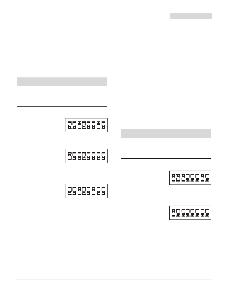
2. Configure the meter per DIP-switch setting #1 in Table 2.
3. Apply a precision 4mA input with proper polarity and adjust R3 until the
meter's display reads "000".
DATEL, Inc., Mansfield, MA 02048 (USA)
∑
Tel: (508)339-3000, (800)233-2765 Fax: (508)339-6356
∑
E-mail: sales@datel.com
∑
Internet: www.datel.com
3 Ω D I G I T , L C D D I S P L A Y , 4 - 2 0 m A L O O P - P O W E R E D M E T E R S
DMS-30LCDA-4/20
4. Apply a precision 20mA input and adjust R7 until the display reads
"1800". Repeat steps 3 and 4 to make sure the adjustments do not affect
one another.
5. Select the appropriate decimal point by setting SW6, SW7 or SW8 to
ON (DP1, DP2 or DP3 respectively).
Table 2. DMS-30LCDA-4/20S (Standard Unipolar)
DIP Switch Settings
NOTE: If a display reading other than "000" to "1000" is desired, refer to
DIP-Switch Settings Table 2 for SW1-SW5 settings
1. Desired display readings are:
4mA ="0.00"
20mA = "6.00"
Use DIP-switch setting #3 in Table 2 and enable decimal point DP2 via
SW7. Apply 4mA and adjust R3 so the display reads "0.00". Apply 20mA
and adjust R7 so the display reads "6.00".
2. Desired display readings are:
4mA =" 000"
20mA = "800"
Use DIP-switch setting #2 in Table 2. Apply 4mA and adjust R3 so the
display reads "000". Apply 20mA and adjust R7 so the display reads
"800". For these display readings, no decimal points are used. Set SW6,
SW7 and SW8 to OFF.
3. Desired display readings are:
4mA = ".000"
12mA = ".250"
This example is not as straightforward as the previous two. Notice that
12mA is exactly halfway between 4mA and 20mA. If we assume that the
input could go up to 20mA, the display reading would then be: 2 x .250 or
".500". From Table 2 we can now select DIP-switch setting #3 and enable
DP1 via SW6. Apply 4mA and adjust R3 so the display reads ".000".
Apply 12mA and adjust R7 so the display reads ".250".
Examples (DMS-30LCDA-4/20S, Unipolar)
DMS-30LCDA-4/20B (Bipolar-Reading
)
The DMS-30LCDA-4/20B's zero-offset circuit differs from the unipolar `S'
model described above in that with the `B' model, a half-scale 12mA input
is typically set to display "000". Therefore, all of the of the DIP-switch
settings in Table 3 assume a reading of "000" is desired with a half-scale
12mA input. Display readings other than those shown in Table 3 are
possible, contact DATEL for more information.
Desired Display Reading
4mA
20mA
SW1
SW2
SW3
SW4
SW5
1. 000 to 1200 to 1999
Off
Off
Off
On
Off
2. 000 to 600 to 1200
On
Off
Off
Off
Off
3. 000 to 400 to 600
Off
Off
On
Off
Off
4. 000 to 200 to 400
On
On
On
Off
Off
5. 000 to 100 to 200
On
On
On
On
Off
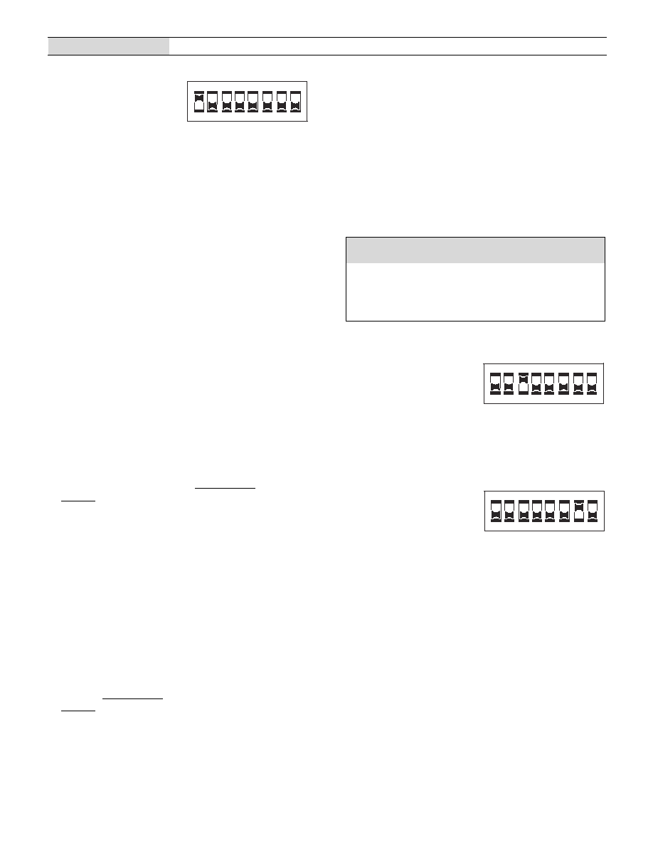
Table 3. DMS-30LCDA-4/20B (Bipolar) DIP Switch Settings
Desired Display Reading
4mA
12mA
20mA
SW1
SW2
SW3
SW4
SW5
1. ≠600 to ≠1000
000
600 to 1000
Off
Off
Off
NA
NA
2. ≠350 to ≠650
000
350 to 650
On
Off
Off
NA
NA
3. ≠250 to ≠400
000
250 to 400
Off
On
Off
NA
NA
4. ≠150 to ≠250
000
150 to 250
Off
Off
On
NA
NA
5. ≠100 to ≠150
000
100 to 150
On
On
On
NA
NA
1. Desired display readings are:
4mA ="≠1.00"
20mA = "1.00"
Use DIP-switch setting #5 in Table 3 and enable decimal point DP2 via
SW7. Apply 12mA and adjust R3 so the display reads "0.00". Apply
20mA and adjust R7 so the display reads "1.00". Apply 4mA and verify
that the display reads "-1.00", readjust R3 and R7 if necessary.
2. Desired display readings are:
4mA =" ≠450"
20mA = "450"
Use DIP-switch setting #2 in Table 3. Apply 12mA and adjust R3 so the
display reads "000". Apply 20mA and adjust R7 so the display reads
"450". Apply 4mA and verify that the display reads "-450". Repeat
adjustment procedure if necessary. For these display readings, no decimal
points are used. Set SW6, SW7and SW8 to OFF.
Examples (DMS-30LCDA-4/20B, Bipolar )
When configuring the DMS-30LCDA-4/20B for the first time, or when
selecting a new range, set both R3 and R7 fully clockwise (roughly 22
turns) to their minimum offset/minimum-span positions, respectively.
Then select the desired readings from Table 3 and configure DIP-
switches SW1, SW2, and SW3 accordingly. Please note, positions SW4
and SW5 are not used in bipolar `B' models.
The procedure below illustrates how to calibrate the DMS-30LCDA-4/20B
to its factory-calibrated readings of "-1000" with a 4mA input and "1000"
with a 20mA input. When performing DIP-switch settings, be sure the
DIP-switch's small actuators are firmly engaged in their fully ON or fully
OFF positions.
1. Set both R3 and R7 fully clockwise.
2. Select DIP-switch setting #1 from Table 3.
3. Apply a precision 12mA input and adjust R3 until the meter's display
reads "000".
4. Apply a precision 20mA input and adjust R7 until the meter's display
reads "1000".
5. Apply a precision 4mA input and the display should read "-1000". Repeat
steps 3 and 4 to make sure the two adjustments did not affect one
5
6
7
8
1
2
3
4
O N
5
6
7
8
1
2
3
4
O N
5
6
7
8
1
2
3
4
O N
5
6
7
8
1
2
3
4
O N
5
6
7
8
1
2
3
4
O N
DMS-30LCDA-4/20
3 Ω D I G I T , L C D D I S P L A Y , 4 - 2 0 m A L O O P - P O W E R E D M E T E R S
3. Desired display readings are:
4mA = "≠650"
20mA = "650"
Notice that these readings can be obtained using either DIP-switch
setting #1 or DIP-switch setting #2 in Table 3. In situations like this
where DIP-switch settings overlap, less-sensitive R3/R7 adjustments
can be achieved if the higher DIP-setting # is selected (setting #2 in this
example). Apply 12mA and adjust R3 so the display reads "000". Apply
20mA and adjust R7 so the display reads "650". Apply 4mA and verify
that the display reads "-650". Repeat adjustments if necessary.
DMS-30LCDA-4/20P (Positive-Reading)
The DMS-30LCDA-4/20P's zero-offset circuit is optimized to produce
positive readings at both 4mA and 20mA input levels. As shown in Table
4's first three columns, a 4mA input can be adjusted (using R3, Zero/
Offset Adjust) to display any positive reading between "000" and "800".
The corresponding 20mA-input reading is then added to the 4mA offset
as a differential whose magnitude is varied by adjusting R7 (Gain/Span
Adjust).
The `Differential Range' column in Table 4 lists the nominal differential
display-readings which can be obtained with R7 at, or very close to, its
full-clockwise, minimum span position. The `Differential Range' column
can be used as a guide when configuring the meter for the majority of
user applications. Higher differential ranges are obtainable; however, the
use of higher differential readings results in correspondingly-lower positive
readings with 4mA inputs, that is, R3's clockwise adjustment-range is
reduced. Example #3 below illustrates this point. Contact DATEL if there
is any doubt as to whether or not the DMS-30LCDA-4/20P can be
configured for your display-reading requirements.
The first step when initially configuring the DMS-30LCDA-4/20P, or when
selecting a new range, is to set R3 fully counterclockwise and R7 fully
clockwise (roughly 22 turns each) to their minimum offset and minimum
span positions, respectively.
The next step is to calculate the differential display-reading; this is
accomplished by subtracting the desired 4mA display reading from the
desired 20mA display reading, disregarding decimal points. Then, using
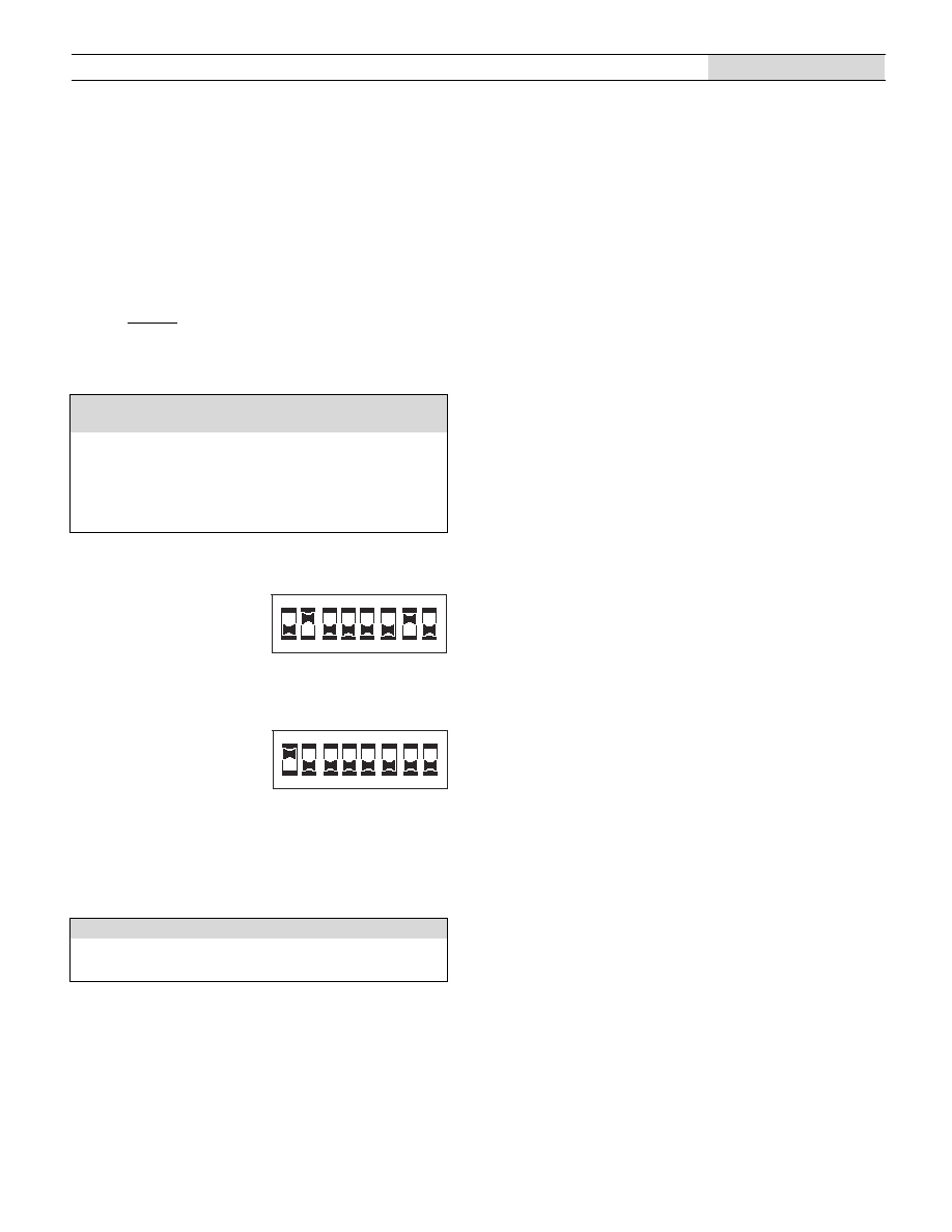
the calculated differential display-reading to select the appropriate DIP-
switch setting # from Table 4, configure DIP-switches SW1, SW2, and
SW3 accordingly. Please note, positions SW4 and SW5 are not used in
positive reading `P' models. Also, make certain that the DIP-switch's
small actuators are firmly engaged in their fully ON or fully OFF
positions.
The example below describes how to calibrate the meter for an
application which the DMS-30LCDA-4/20P easily accommodates:
displaying the output of a 4-20mA transmitter, that is, "04.0" with a 4mA
input and "20.0" with a 20mA input.
1. Set R3 fully counterclockwise (minimum offset position) and R7 fully
clockwise (minimum differential span position), roughly 22 turns.
2. Subtract 040 from 200 to yield a differential-reading value of 160; use this
value to select DIP-switch setting #5 in Table 4. Enable decimal point
DP3 by placing SW8 to the ON position.
3. Set the transmitter's output to 4.0mA and carefully adjust R3 clockwise
until the meter's display reads "000".
4. Set the transmitter's output to 20.0mA and adjust R7 counterclockwise
until the meter's display reads "16.0".
5. Set the transmitter back to 4.0mA and slowly adjust R3 clockwise until
the display reads "04.0". Reapply 20.0mA and the display should now
read "20.0". Repeat steps 3, 4, and 5 to make sure the adjustments did
not affect one another.
Table 4. DMS-30LCDA-4/20P (Positive Reading)
DIP Switch Settings
Desired Display Readings
Diff. Range
4mA
20mA
SW1
SW2
SW3
SW4
SW5
1. 800 to 1400
900
1700
Off
Off
Off
NA
NA
2. 500 to 800
850
1350
On
Off
Off
NA
NA
3. 350 to 500
800
1150
Off
On
Off
NA
NA
4. 250 to 350
750
1000
Off
Off
On
NA
NA
5. 150 to 250
750
900
On
On
On
NA
NA
1. Desired display readings are:
4mA ="650"
20mA = "950"
Use DIP-switch setting #4 in Table 4 since subtracting 650 from 950
yields a differential value of 300. Apply 4mA and adjust R3 until the
display reads "000". Apply 20mA and adjust R7 until the display reads
"300" (the differential value previously calculated). Apply 4mA and adjust
R3 until the display reads "650". Apply 20mA and verify that the display
reads "950".
2. Desired display readings are:
4mA =" 4.00"
20mA = "19.99"
This example illustrates the DMS-30LCDA-4/20P's capability to display
higher differential readings than those indicated in Table 4. This example
also illustrates how the DMS-30LCDA-4/20P can be used to display the
output levels of a 4-20mA transmitter with higher precision (0.01mA
versus 0.1mA) than the example previously described.
Subtracting 400 from 1999 yields a differential of 1599, a value not listed
in Table 4. However, use DIP-switch setting #1 in Table 4 since this
setting has the highest overall offset/span adjustment capabilities. Enable
DP2 via SW7, then apply 4mA and adjust R3 so the display reads "0.00".
Apply 20mA and adjust R7 so the display reads "15.99". Apply 4mA and
adjust R3 until the display reads "4.00". Apply 20mA and check to see
that the display reads "19.99" or just overranges ("1--"). Repeat
adjustment procedure if necessary.
Examples (DMS-30LCDA-4/20I, Positive Reading)
5
6
7
8
1
2
3
4
O N
5
6
7
8
1
2
3
4
O N
5
6
7
8
1
2
3
4
O N
DATEL, Inc., Mansfield, MA 02048 (USA)
∑
Tel: (508)339-3000, (800)233-2765 Fax: (508)339-6356
∑
E-mail: sales@datel.com
∑
Internet: www.datel.com
3 Ω D I G I T , L C D D I S P L A Y , 4 - 2 0 m A L O O P - P O W E R E D M E T E R S
DMS-30LCDA-4/20
DMS-30LCDA-4/20I (Inverse Reading)
The DMS-30LCDA-4/20I is designed to accommodate applications
where an increasing loop current produces a decreasing display
reading. That is, as the loop current is increased from 4mA to 20mA, the
display will read a user determined full-scale positive number at 4mA and
then decrease to "000" at 20mA. The `4/20I' model is essentially a `-4/
20S' model operating in reverse. Table 5 and the two examples that
follow describe the operation of this model in greater detail.
The first step when configuring the DMS-30LCDA-4/20I for the first
time, or when changing to a different range, is to set both R3 and R7 to
their full clockwise positions, roughly 22 turns. Next, using the desired
display readings, select the appropriate DIP-switch setting number from
Table 5.
Examples (DMS-30LCDA-4/20I, Inverse Reading)
1. Desired display readings are:
4mA = "6.00"
20mA = "0.00"
Use DIP-switch setting #3 in Table 5 and enable decimal point DP2 via
SW7. Apply 20mA and adjust R3 so the display reads "0.00". Apply 4mA
and adjust R7 so the display reads "6.00".
2. Desired display readings are:
4mA = "800"
20mA = "000"
Use DIP-switch setting #2 in Table 5. Apply 20mA and adjust R3 so the
display reads "000". Apply 4mA and adjust R7 so the display reads "800".
For these display readings, no decimal points are used. Set SW6, SW7
and SW8 to OFF.
Table 5. DMS-30LCDA-4/20I (Inverse Reading) DIP Switch Settings
Desired Display Reading
4mA
20mA
SW1
SW2
SW3
SW4
SW5
1. 1999 to 1300
000
Off
Off
Off
Off
NA
2. 1300 to 850
000
On
Off
Off
Off
NA
3.
850 to 550
000
Off
On
Off
Off
NA
4.
550 to 350
000
Off
Off
On
Off
NA
5.
350 to 200
000
On
On
On
Off
NA
6.
200 to 130
000
On
On
On
On
NA
Table 6. Decimal Point Selections (All Models)
To turn on a decimal point, place its respective DIP switch to the fully ON position.
SW6
SW7
SW8
DP1
DP2
DP3
5
6
7
8
1
2
3
4
O N
5
6
7
8
1
2
3
4
O N
DATEL, Inc. 11 Cabot Boulevard, Mansfield, MA 02048-1151
Tel: (508) 339-3000 (800) 233-2765 Fax: (508) 339-6356
Internet: www.datel.com E-mail: sales@datel.com
DATEL (UK) LTD. Tadley, England Tel: (01256)-880444
DATEL S.A.R.L. Montigny Le Bretonneux, France Tel: 01-34-60-01-01
DATEL GmbH M¸nchen, Germany Tel: 89-544334-0
DATEL KK Tokyo, Japan Tel: 3-3779-1031, Osaka Tel: 6-6354-2025
DATEL makes no representation that the use of its products in the circuits described herein, or the use of other technical information contained herein, will not infringe upon existing or future patent rights. The descriptions contained
herein do not imply the granting of licenses to make, use, or sell equipment constructed in accordance therewith. Specifications are subject to change without notice. The DATEL logo is a registered DATEL, Inc. trademark.
Æ
Æ
ISO 9001
ISO 9001
R
E
G
I
S
T
E
R
E
D
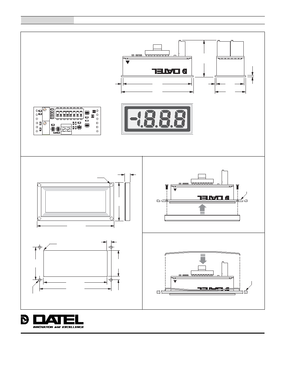
Mechanical Specifications
MECHANICAL DIMENSIONS: Inches (mm)
TOLERANCES:
2 PL DEC ±0.02 (±0.51)
3 PL DEC ±0.010 (±0.254)
WIRE SIZE:
18 to 26 AWG
(Solid or stranded)
STRIPPING LENGTH:
0.20" (5.08mm)
DIP
Switches
Gain
Adjust
Zero
Adjust
+
≠
Loop
Input
DP2
(SW7)
DP3
(SW8)
DP1
(SW6)
#2-56 INSERT
0.156 (3.96) DEEP
FRONT VIEW
1.270
(32.26)
0.187
(4.75)
OPTIONAL BEZEL (DMS-BZL1 and DMS-BZL2)
2.35 (59.69)
2.118 (53.80)
0.093 (2.362) DIAMETER (4 REQUIRED)
ONLY WHEN USING OPTIONAL BEZEL ASSEMBLY
RECOMMENDED DRILL AND PANEL CUTOUT DIMENSIONS
INTERNAL CORNER RADII:
0.032 (0.81) MAX.
1.07
(27.18)
0.878
(22.30)
0.096
(2.44)
0.116
(2.95)
2.55 (64.77)
PANEL CUTOUT
MA
DE IN
USA
Æ
Æ
BEZEL INSTALLATION
PANEL
BEZEL
Back View
Front View
DMS-30LCDA-4/20
3 Ω D I G I T , L C D D I S P L A Y , 4 - 2 0 m A L O O P - P O W E R E D M E T E R S
1
R 3
Z e r o
A d j u s t
R 7
G a i n
A d j u s t
5
6
7
8
1
2
3
4
O N
+
T B 1
M
A
D
E
IN
U
S
A
D
M
S
-3
0L
C
D
A
-4
/2
0S
0 . 9 2
( 2 3 . 4 )
0 . 8 4
( 2 1 . 3 )
Æ
Æ
0 . 0 4 0
( 1 . 0 2 )
0 . 9 0
( 2 2 . 9 )
2 . 1 7
( 5 5 . 1 )
2 . 0 9
( 5 3 . 1 )
0 . 0 4 0
( 1 . 0 2 )
0 . 0 4 0
( 1 . 0 2 )
M
A
D
E
IN
U
S
A
Æ
Æ
R E T A I N I N G C L I P I N S T A L L A T I O N
P A N E L
DS-0303D 1/03