DATEL, Inc., Mansfield, MA 02048 (USA)
∑
Tel: (508)339-3000, (800)233-2765 Fax: (508)339-6356
∑
Email: sales@datel.com
∑
Internet: www.datel.com
Features
∑∑
∑∑
∑
Precision, autozeroing, factory-
calibrated A/D converter
∑∑
∑∑
∑
Scientific-grade accuracy, ±2 counts
∑∑
∑∑
∑
Miniature size:
2.17" x 0.92" x 0.56"
55mm x 23mm x 14mm
∑∑
∑∑
∑
Large (0.52"/13.2mm) LED display
∑∑
∑∑
∑
Choice of red, green or yellow colors
∑∑
∑∑
∑
High-intensity or low-power red
LED's optional
∑∑
∑∑
∑
Single +5V supply (175mW for low-
power models)
∑∑
∑∑
∑
Epoxy-encapsulated, 12-pin DIP with
built-in color filter and bezel
∑∑
∑∑
∑
3 differential input voltage ranges
∑∑
∑∑
∑
DISPLAY HOLD and TEST functions
∑∑
∑∑
∑
Optional BCD data outputs for CPU
interface
∑∑
∑∑
∑
0 to +50∞C temperature range
4Ω Digit, LED Display
Precision, Miniature
Digital Panel Voltmeters
DMS-40PC Series, 4Ω Digit, LED Display, Miniature DPM's are fully self-contained,
component-like, plug-in meters that provide scientific-grade accuracy (typically ±2
counts or ±0.005% of full scale) and outstanding reliability at a very affordable price.
Within its miniature (2.17" x 0.92" x 0.56"), epoxy-encapsulated package, each
meter contains a precision reference circuit; a high-resolution, autozeroing, factory-
calibrated A/D converter; and a large (0.52"/13.2mm), easy-to-read, LED display.
LED's are available in red, yellow and green colors. Red LED's are also offered in
high-intensity or low-power versions.
The versatile design of the DMS-40PC Series assures trouble-free installation and
long-term operation. Differential input voltage ranges include ±2V, ±20V and ±200V.
Input impedance is a minimum 800k
. Non-inverting inputs are overvoltage protected
to ±250V, and CMRR is typically 86dB (dc to 60Hz).
The DMS-40PC's epoxy-encapsulated package has an integral bezel and color
filter. The moisture and vibration-proof package is extremely rugged and well suited for
harsh environments and extended temperatures. Devices are fully specified for
0 to +50∞C operation.
All models operate from a single +5V supply and typically consume 500mW. Low-
power models, whose display is just as bright as standard models, typically consume
175mW. DISPLAY TEST and HOLD functions are standard on each meter, and a
complete set of BCD outputs are optional for sending data to CPU's or remote
displays.
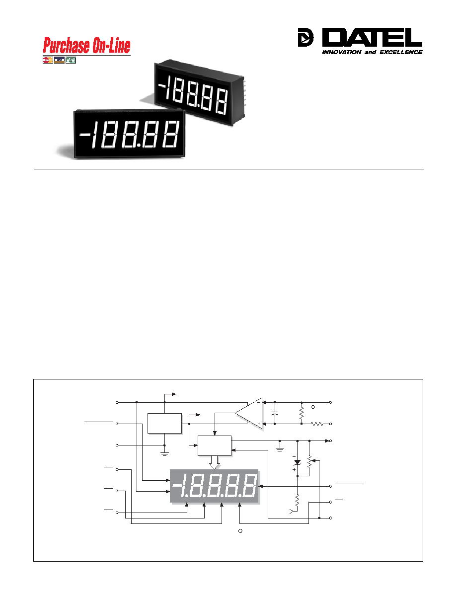
Figure 1. DMS-40PC Series Simplified Schematic
DMS-40PC Series
Actual Size
(+) INPUT HI
(≠) INPUT LO
ANALOG
COMMON
DP4
REFERENCE IN/OUT
+5V SUPPLY
R1
DP 1
DP 2
DP 3
6
5
4
9
11
12
10
8
7
1
3
DC/DC
CONVERTER
2
5V RETURN
+5V
≠5V
+5V
2.5V
REF.
R2
DATA
V+
V≠
A/D
CONVERTER
0 Vdc
0.01µF
DISPLAY HOLD
DISPLAY TEST
R2 is not used on ±2V (-1) models.
R2 = 101k on ±20V (-2) models and 9.2k on ±200V (-3) models.
909k
1
1
Æ
Æ
www.datel.com
2
DMS-40PC
4 Ω D I G I T , L E D D I S P L A Y D I G I T A L P A N E L V O L T M E T E R S
Performance/Functional Specifications
Typical at T
A
= +25∞C and supply voltage = +5V using the single-ended input circuit,
unless otherwise noted.
Applies for transient or continuous overvoltages applied to (+) INPUT HI (pin 11)
with (≠) INPUT LO (pin 12) properly connected. Pin 12 is not overvoltage protected
(see Figure 1). Voltages applied to pin 12 should not exceed the supply voltage.
See Technical Notes.
BCD outputs are optional and must be specified in the part number.
See Ordering Information.
Includes high-intensity and BCD-output models.
Accessories:
DMS-PS1-CM
+5V/1.0A AC/DC power supply module
DMS-30-CP
Panel cutout punch
DMS-BZL1
DMS-40 bezel assembly
DMS-BZL2
DMS-40 bezel assembly with sealing gasket
DMS-EB
Application/evaluation board with standard
MOLEX connector, decimal point solder pads
and attenuation resistor pads.
BCD Output Models:
BCD outputs are only available on standard red meters.
DMS-40PC-1-RS-BCD for ±2V input range
DMS-40PC-2-RS-BCD for ±20V input range
DMS-40PC-3-RS-BCD for ±200V input range
DMS-40PC-1-RL-BCD for ±2V input range
DMS-40PC-2-RL-BCD for ±20V input range
DMS-40PC-3-RL-BCD for ±200V input range
DMS-40PC - 1 - R S
Technical Notes
1. ANALOG COMMON (Pin 10): This pin is an internal, low-noise
ground for the DMS-40PC. It is internally connected to pin 3
(5V RETURN). Do not connect pin 10 to either pin 3 or your
system ground as this will create a ground loop and possibly result
in erroneous readings.
2. REFERENCE INPUT/OUTPUT (Pin 7): This pin accesses the
meter's internal reference and is used during the factory calibration
procedure. Pin 7 should be left open in most common applications.
It can be used in certain "ratiometric" applications in which it is
desirable for the meter's reference to track an external reference.
See Ap Note 3 in the DATEL Panel Meter Catalog for more details.
3. DISPLAY TEST (Pin 2): Connecting pin 2 to ground (pin 3, 5V
RETURN) will activate all LED segments, and the display will read
"≠18888" regardless of the actual applied input. To reduce self-
heating, the display should not be left in the "test" mode for
more than 10 seconds. This pin should be left open if unused.
4. DISPLAY HOLD (Pin 9): For normal operation, this pin should be
left open. To hold the meter's last reading and display it continu-
ously, tie pin 9 to ground (pin 3, 5V RETURN).
5. Decimal Point Placement: The location of the decimal point is
user-selectable, and the decimal point control pins (DP1-DP4) are
active low functions. Select the appropriate decimal point by tying
pin 4, 5, 6 or 8 to pin 3 (5V RETURN). Unused decimal point
location pins should be left open.
Ordering Information
LED Color:
GS = Standard Green
RH = High-Intensity Red
RL = Low-Power Red
RS = Standard Red
YS = Standard Yellow
Input Range:
1 = ±2V
2 = ±20V
3 = ±200V
A panel-mount retaining clip is supplied with each model.
Analog Inputs
Min.
Typ.
Max.
Units
Full Scale Input Range:
DMS-40PC-1
--
±2
--
Volts
DMS-40PC-2
--
±20
--
Volts
DMS-40PC-3
--
±200
--
Volts
Input Impedance:
DMS-40PC-1
100
1000
--
M
DMS-40PC-2, -3
0.8
1
--
M
Overvoltage Protection
--
--
±250
Volts
Common Mode Voltage Range
--
--
±2
Volts
CMRR (dc to 60Hz)
--
86
--
dB
Control Inputs
Decimal Point Placement (Pins 4-6, 8)
Tie to pin 3 to activate
Display Test (Pin 2)
Tie to pin 3 to activate all segments
Display Hold (Pin 9)
Tie to pin 3 to hold last reading
BCD Outputs
Logic levels (1 LSTTL load max.):
Logic "1"
+2.4
--
--
Volts
Logic "0"
--
+0.4
+0.8
Volts
Performance
Sampling Rate
2.5 samples per second
Accuracy (15 minute warm-up):
DMS-40PC-1 (V
IN
= +1.9V)
--
±2
±3
Counts
DMS-40PC-2 (V
IN
= +19V)
--
±3
±4
Counts
DMS-40PC-3 (V
IN
= +190V)
--
±3
±4
Counts
Zero Reading (V
IN
= 0 Volts)
"≠ 0001"
"0000"
"0001"
Temperature Drift (0 to +50∞C):
DMS-40PC-1
--
±0.4
±1
Cnts/∞C
DMS-40PC-2, -3
--
±0.4
±1.5
Cnts/∞C
Power Supply Requirements
Supply Voltage
+4.75
+5.00
+5.25
Volts
Supply Current:
Standard Models
--
+100
+140
mA
Low-Power Models
--
+35
+50
mA
Display
Display Type and Size
4Ω Digit LED, 0.52"/13.2mm high
Polarity Indication
Autopolarity ("≠" for negative V
IN
)
Overrange Indication
"≠ 0000" (flashing) for negative V
IN
"0000" (flashing) for positive V
IN
Physical/Environmental
Operating Temperature
0
--
+50
∞C
Storage Temperature
≠20
--
+75
∞C
Humidity (Non-condensing)
0
--
95
%
Case Material
Polycarbonate
Weight
0.75 ounces (21 grams)
Order on-line at www.datel.com
3
4 Ω D I G I T , L E D D I S P L A Y D I G I T A L P A N E L V O L T M E T E R S
DMS-40PC
Applications
The DMS-40PC's simplified schematic, shown in Figure 1, can be
very useful when debugging a malfunctioning circuit, especially if
the user has some knowledge of operational amplifiers (op amps).
The meter's high-impedance input consists of an op amp powered
from a ±5Vdc power supply (the ≠5V is internally generated). Figure
1 shows that input signals applied to (≠) INPUT LO and (+) INPUT
HI must to be kept within the ±5V power-supply rails. Also note that
only pin 11 has a current-limiting 909k
series resistor. High input
voltages that have a common ground connection with pin 3 (5V
RETURN) should only be applied to pin 11 ((+) INPUT HI) and never
to pin 12. In these high-voltage cases, pin 12 should always be tied
to pin 3 (5V RETURN).
One of the simplified schematic's more noteworthy features is that it
shows some DMS-40PC internal voltage values and also that pin 3
is the meter's zero-volt reference point -- regardless of the type of
power or signal source used. This is an important point to keep in
mind when using digital multimeters to perform system-level
measurements. The multimeter's negative lead (usually the black
one) must always be connected to pin 3 (5V RETURN). This is the
only way accurate readings can be made, particularly if the meter is
configured for a differential input and concerns arise regarding
common-mode voltages.
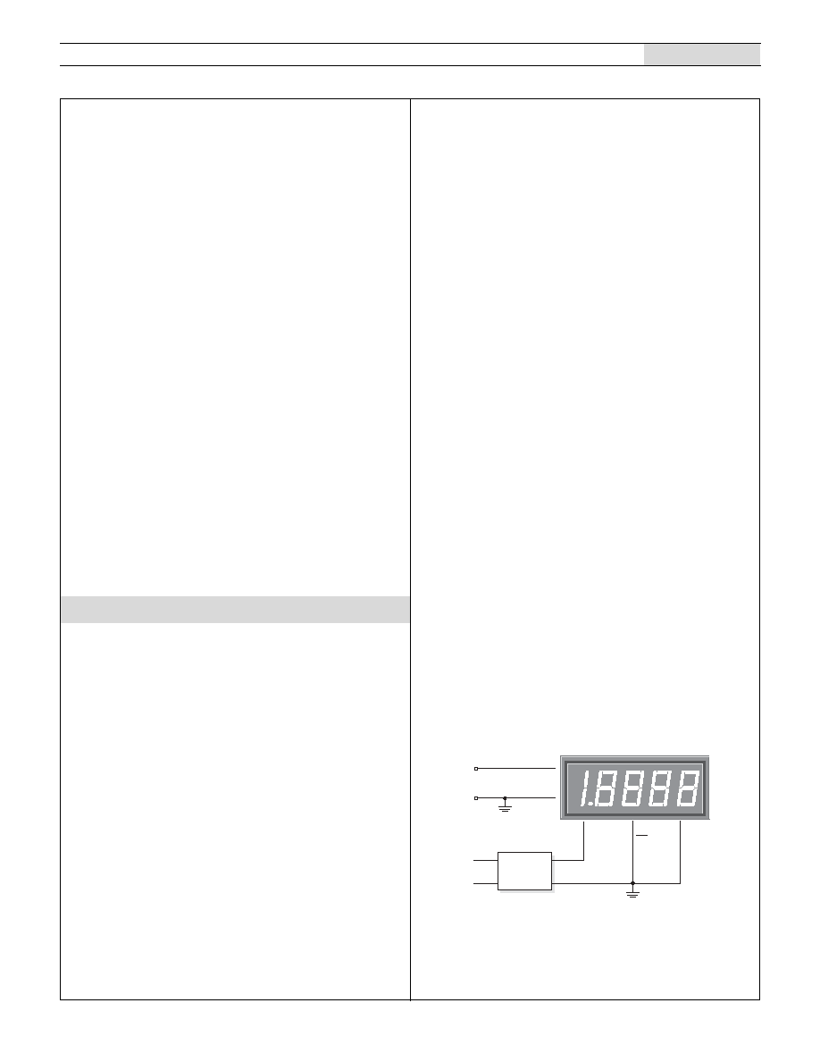
1. Single-Ended Input Configurations: The DMS-40PC can
measure single-ended signals with either positive or negative
polarities. True single-ended inputs always have one of their two
terminals at the same potential as the DMS-40PC's 5V RETURN
(pin 3). Single-ended inputs are usually derived from power
supplies that have a common ground with the meter's +5V
supply. Figure 2 shows the recommended connections to be
used with this type of input. Pin 12, (≠) INPUT LO, is shown
directly tied to ground. This connection to ground must be a
separate wire or pc-board trace originating at V
IN
's negative
terminal. This hook-up will normally eliminate display instabilities
and errors caused by ground-loop currents which can occur if
(≠) INPUT LO is tied to ground at, or near, pin 3.
Hard wiring is preferable, however, you can exercise dynamic
control over the location of the decimal point by employing drive
circuits that are capable of sinking a minimum of 20mA at
voltages less than +0.4 Volts.
6. Gain Adjust: There is a gain-adjust potentiometer on the back
of each meter. It has approximately ±150 counts of adjustment
range. Since these meters essentially have no zero/offset errors,
a gain adjustment is effectively an overall accuracy adjustment.
Though they may be performed at any point (except zero),
accuracy adjustments are most effective when performed with
higher level input signals.
7. Soldering Methods: All models in the DMS-40PC Series easily
withstand most common wave soldering operations. We
recommend, however, that you evaluate the effects your
particular soldering techniques may have on the meter's plastic
case and high-precision electrical performance. We recommend
the use of water-soluble solders and thorough cleaning
procedures.
8. Suggested Mating Connectors:
Panel mounted:
Connector housing
DATEL P/N 39-2079400
Terminal type
DATEL P/N 39-2099090
Crimping tool
DATEL P/N 39-2099000
Wire size
22 to 26 AWG
Insulation diameter
0.062" (1.57mm) maximum
Stripping length
0.100 to 0.125" (2.54 to 3.17mm)
Board mounted:
Socket
DATEL P/N 39-2359625
DMS-40PC Series meters are high-precision versatile devices that
can be used in many applications requiring a 0 to 19,999 count
digital display. The application circuits chosen for this section are
ones that have historically received many inquiries. Every attempt
has been made to ensure technical accuracy, and all of the following
circuits have been prototyped and tested to ensure functionality.
Please keep in mind, however, that real-world applications are
seldom as straightforward as the approaches presented here.
All inputs applied to DMS-40PC meters must be steady, dc values,
otherwise the input itself may cause display instabilities. Due to their
4Ω digit resolution, DMS-40PC meters must be wired with greater
care than their 3Ω digit counterparts. Correct power-supply and
input-signal wiring -- an absolute must! -- helps eliminate ground-
loop induced errors that show up as unstable display readings.
When an input signal, assumed to be exactly zero volts, has a 1mV
(0.001V) ground-loop induced offset, it is displayed as "0010" on a
±2V input-range meter! DATEL's new Digital Panel Meter Catalog
contains an application note describing power supply wiring and
ground loop avoidance techniques.
Figure 2. Single-Ended Input Configuration
1
1 2
3
+ 5 V S U P
( ) I N L O
5 V R E T
1 1
( + ) I N H I
6
D P 1
+
A C t o D C C o n v e r t e r
V
I N
D M S - 4 0 P C - 1 - G S
D A T E L
D M S - P S 1 - C M
8 5 - 2 6 4 V a c
4
DMS-40PC
4 Ω D I G I T , L E D D I S P L A Y D I G I T A L P A N E L V O L T M E T E R S
Applications
which low calibration drift is desirable. When using other, higher-
power, DMS-40PC models in combination with three-terminal
regulators, be sure to consult the regulator manufacturer's data
sheet to ensure the device is being utilized safely and correctly.
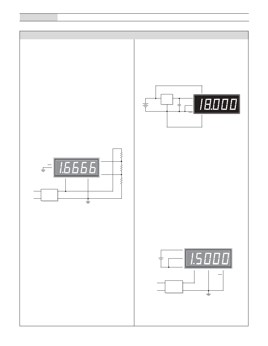
Figure 4. 4.5-18V Power Supply Monitor
4. Floating Signal Source Measurements: A floating input is a
signal that, before it is applied to the DMS-40PC's inputs, has no
galvanic connection (direct current path) to the meter or the
meter's power supply. The circuit shown in Figure 5 illustrates
the necessary connections for measuring floating inputs. The
1.5V battery represents a true floating input signal since it
initially has no connection whatsoever in common with the
meter. Real-world floating inputs typically originate from power
supplies which are transformer isolated from the DMS-40PC's
+5V supply.
The connection of pin 12 ((≠) INPUT LO) to pin 10 (ANALOG
COMMON) is required in order to provide a bias return for the
meter's input amplifier. This is because neither pin 11 nor pin 12
are tied to any reference voltage inside the DMS-40PC (see
Figure 1). These connections are not made internally in order to
give the meter the ability to make differential measurements as
described in a previous section.
Figure 5. Floating Input Measurements
3. Power Supply Monitoring: One of the most widely used digital
panel voltmeter applications is monitoring the output voltage of a
system power supply -- often the same supply that also powers
the meter. The low-power, red LED DMS-40PC-2-RL, with its
excellent 0.001Vdc resolution, can be configured to monitor
power supplies with outputs in the range of 4.5-18Vdc. The
circuit in Figure 4 uses a low-drop-out, three-terminal regulator
(LM-2931T-5, in a T0-220 package, available from National
Semiconductor) to provide regulated 5V power to the meter.
The LM-2931 was chosen because it has the following on-chip
protection features: reverse polarity, short circuit and thermal
runaway. The DMS-40PC-3-RL can monitor voltages up to
±200Vdc, provided a separate +5V power source is used since
many three-terminal regulators cannot operate with supply
voltages greater than 24V. Red, low-power LED models, with
their very low self-heating, are recommended for applications in
Figure 3. Differential Input Configuration
2. Differential Input Configurations: Differential inputs can also
be measured with DMS-40PC meters as shown in the circuit of
Figure 3. Differential inputs must also originate from power
supplies that have a common ground with the meter's 5V
RETURN (pin 3). However, differential inputs usually have both
terminals above and/or below 5V RETURN. Figure 3, though not
necessarily a typical real-world application, does serve the
purpose of illustrating the concept of a differential signal.
The voltages developed across R1, R2 and R3 are equal to each
other and measure approximately +1.6666Vdc or 1/3 of the +5V
power source. More importantly, while the signal across R3 is
single-ended, both ends of R1 and R2 are well above ground
and are described here as being differential. Please note that
while the DMS-40PC can measure the voltages across either R2
or R3, it cannot measure the +1.6666 volts across R1! The
voltage at the lower end of R1 is approximately 3.333V and this
exceeds the common mode voltage limit of ±2V.
1
1 2
3
+ 5 V S U P
( ) I N L O
5 V R E T
1 1
( + ) I N H I
D P 1
A C t o D C C o n v e r t e r
R 2
R 1
R 3
1 k
1 k
1 k
D M S - 4 0 P C - 1 - G S
D A T E L
D M S - P S 1 - C M
8 5 - 2 6 4 V a c
DMS-40PC-2-RL
5
12
+
≠
11
1
4.5 - 18Vdc
LM2931T-5
GND
IN
OUT
+5V SUP
3
5V RET
DP2
(+) IN HI
(≠) IN LO
22µF
10V
+
1
3
+ 5 V S U P
5 V R E T
6
D P 1
A C t o D C C o n v e r t e r
D M S - 4 0 P C - 1 - G S
1 2
( ) I N L O
1 1
( + ) I N H I
1 . 5 V
C E L L
+
1 0
A N A C O M M
D A T E L
D M S - P S 1 - C M
8 5 - 2 6 4 V a c
5
4 Ω D I G I T , L E D D I S P L A Y D I G I T A L P A N E L V O L T M E T E R S
DMS-40PC
Applications
5. Engineering Scaling and Input Attenuation: In many
applications, the input signal must be scaled, or divided down,
before being applied to the DMS-40PC. In some situations, the
input signal exceeds the full-scale range of the meter, and in
other applications, a direct one-to-one relation does not exist
between the input voltage and the desired display reading. For an
example of the second situation, assume an input voltage of
1.0Vdc is required to display a reading of "7500" when applied to
a ±2V input meter. An input divider circuit, constructed with two
series resistors with an output-to-input ratio of 0.75, will scale the
1.0V signal down to 0.75V.
Engineering scaling and input attenuation are discussed in Ap
Note 4 of the DATEL Digital Panel Voltmeter Catalog. Compen-
sating for inputs which have a zero offset is also discussed.
6. BCD Outputs (DMS-40PC-X-RS and -RL-BCD Models Only):
Models with a "-BCD" suffix have 12 extra output pins, labeled
A through L (6 per side), that provide the following information:
multiplexed serial BCD data, digit drive, and polarity indication.
The data present on pins A - L simultaneously drives the meter's
internal LED display. All functions on pins A - L are 5V CMOS
compatible, however, they are only rated to drive one, 74LS
series, TTL load. CMOS logic IC's, for example 74HC or 74HCT
series devices, should be used when more fan-out capability
is required.
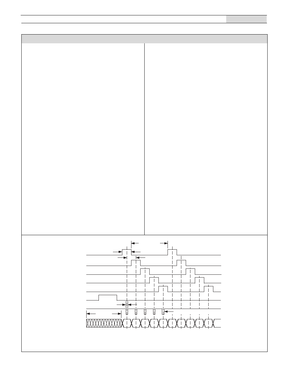
As the timing diagram in Figure 5 indicates, 100Hz is the
optimum display scan rate when the BCD outputs are used to
drive external LED displays. Faster scan rates, while permissible,
are not necessary. Slower scanning, however, may result in
noticeable "flickering" of the display. Common anode LED's,
combined with a 74LS247 BCD to seven-segment decoder, is the
simplest way of implementing an external display. A seventy-five
to one-hundred Ohm resistor on each LS247 segment-drive
output provides adequate display brightness.
The functions of pins A - L are listed below:
BCD DATA (pins I - L): Four lines are used for BCD (Binary Coded
Decimal) data outputs, representing the numbers 0 - 9. Positive-logic
convention (a high represents a "1") is used.
DIGIT DRIVE ( pins A - E): These five outputs, when gated with
STROBE, can be used to direct the BCD DATA into external latches.
DIGIT DRIVE outputs may also be connected directly to the bases of
NPN transistors in remote-display configurations. The digits are
scanned right-to-left, i.e., MSD (DIGIT 1 DRIVE) to LSD (DIGIT 5
DRIVE).
BUSY (pin G): This is a status pin that goes high at the start of an
analog-to-digital (A/D) conversion cycle and remains high until the
conversion ends.
STROBE (pin H): A string of five sequential, active-low, STROBE
pulses are output (after BUSY goes low) indicating the end of a
conversion and the availability of new data. The 5 STROBE pulses
occur only once per conversion, or 2.5 times each second. STROBE
can be used to latch the BCD data (on pins I - L) into external
latches. Either edge can be used since STROBE (~ 5µsec wide) is
active only in the center of the corresponding DIGIT DRIVE and BCD
DATA outputs.
POLARITY (pin F): This pin, which is also used inside the DMS-
40PC to drive the negative-sign segment, indicates whether the last
input signal conversion was positive (POLARITY set high) or
negative (POLARITY set low). POLARITY, unlike BCD DATA, is not
multiplexed. For data latching purposes, POLARITY should be
sampled during the STROBE pulse for digit 1 (most significant digit).
Figure 6. BCD Data Timing Diagram
DIGIT DRIVE 1
(MSD)
Data from
Previous Conversion
DIGIT DRIVE 2
DIGIT DRIVE 3
DIGIT DRIVE 4
DIGIT DRIVE 5
(LSD)
STROBE OUT
BCD DATA
(4 LINES)
Approx. 5µsec
5 Strobes Only Per Conversion
Approx. 2msec
Approx. 2msec
Approx. 8msec
BUSY
1
MSD
2
3
4
5
LSD
1
2
3
4
5
DATEL, Inc. 11 Cabot Boulevard, Mansfield, MA 02048-1151
Tel: (508) 339-3000 (800) 233-2765 Fax: (508) 339-6356
Internet: www.datel.com Email: sales@datel.com
DATEL (UK) LTD. Tadley, England Tel: (01256)-880444
DATEL S.A.R.L. Montigny Le Bretonneux, France Tel: 01-34-60-01-01
DATEL GmbH M¸nchen, Germany Tel: 89-544334-0
DATEL KK Tokyo, Japan Tel: 3-3779-1031, Osaka Tel: 6-354-2025
DATEL makes no representation that the use of its products in the circuits described herein, or the use of other technical information contained herein, will not infringe upon existing or future patent rights. The descriptions contained herein
do not imply the granting of licenses to make, use, or sell equipment constructed in accordance therewith. Specifications are subject to change without notice. The DATEL logo is a registered DATEL, Inc. trademark.
Æ
Æ
ISO 9001
ISO 9001
R
E
G
I
S
T
E
R
E
D
DS-0272C 1/98
DMS-40PC
4 Ω D I G I T , L E D D I S P L A Y D I G I T A L P A N E L V O L T M E T E R S
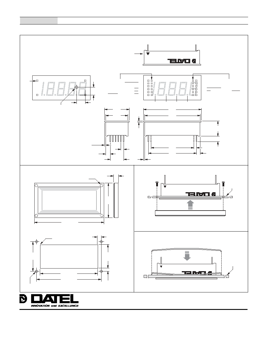
Mechanical Specifications
MECHANICAL DIMENSIONS: Inches (mm)
TOLERANCES: 2 PL DEC ±0.02 (±0.51)
3 PL DEC ±0.010 (±0.254)
LEAD DIMENSIONS: 0.025 (0.635) x 0.025 (0.635) NOMINAL
RECOMMENDED PC BOARD FINISHED HOLE DIAMETER:
0.042 ±0.003 (1.067 ±0.076)
#2-56 INSERT
0.156 (3.96) DEEP
FRONT VIEW
1.270
(32.26)
0.187
(4.75)
OPTIONAL BEZEL (DMS-BZL1 and DMS-BZL2)
2.35 (59.69)
2.118 (53.80)
0.093 (2.362) DIAMETER (4 REQUIRED)
ONLY WHEN USING OPTIONAL BEZEL ASSEMBLY
RECOMMENDED DRILL AND PANEL CUTOUT DIMENSIONS
INTERNAL CORNER RADII:
0.032 (0.81) MAX.
1.07
(27.18)
0.878
(22.30)
0.096
(2.44)
0.116
(2.95)
2.55 (64.77)
PANEL CUTOUT
MA
DE IN
USA
Æ
Æ
BEZEL INSTALLATION
PANEL
BEZEL
Æ
Æ
RETAINING CLIP INSTALLATION
PANEL
B4
B2
B1 (LSB)
B8 (MSB)
STROBE
BUSY
MADE I
N US
A
DMS-
40PC-
X-X
X
FRONT VIEW
+5V SUPPLY
DISPLAY TEST
5V RETURN
DP3
DP2
DP1
1
2
3
4
5
6
(≠) INPUT LO
(+) INPUT HI
ANALOG COMMON
DISPLAY HOLD
DP4
REFERENCE IN/OUT
12
11
10
9
8
7
DP1
DP2
DP3
DP4
2.17
(55.1)
2.09
(53.1)
1.80
(45.7)
0.25 (6.4) TYP.
0.15
(3.7) TYP.
0.040
(1.02)
0.10
(2.5)
TYP.
0.040
(1.02)
0.17
(4.3)
TYP.
0.50
(12.7)
0.84
(21.3)
0.92
(23.4)
PIN #1
IDENTIFIER
0.560
(14.22)
Æ
Æ
(LSD) DIGIT 5
(MSD) DIGIT 1
DIGIT 2
DIGIT 3
DIGIT 4
POLARITY
A
B
C
D
E
F
L
K
J
I
H
G
INSIDE ROW (BCD MODELS ONLY)
(BCD MODELS ONLY)
1.60
(40.6)
0.10
(2.5) TYP.
A
B
C
D
E
F
L
K
J
I
H
G
INSIDE ROW (BCD MODELS ONLY)
0.040
(1.02)
0.325
(8.26)
0.290
(7.37)
PIN 1
CALIBRATION POTENTIOMETER HOLE LOCATION
0.125 (3.175) DIAMETER
(USE ONLY WHEN PC BOARD MOUNTING)