DATEL, Inc., Mansfield, MA 02048 (USA)
∑
Tel: (508)339-3000, (800)233-2765 Fax: (508)339-6356
∑
Email: sales@datel.com
∑
Internet: www.datel.com
DATEL makes no representation that the use of its products in the circuits described herein, or the use of other technical information contained herein, will not infringe upon existing or future patent rights. The descriptions contained
herein do not imply the granting of licenses to make, use, or sell equipment constructed in accordance therewith. Specifications are subject to change without notice. The DATEL logo is a registered DATEL, Inc. trademark.
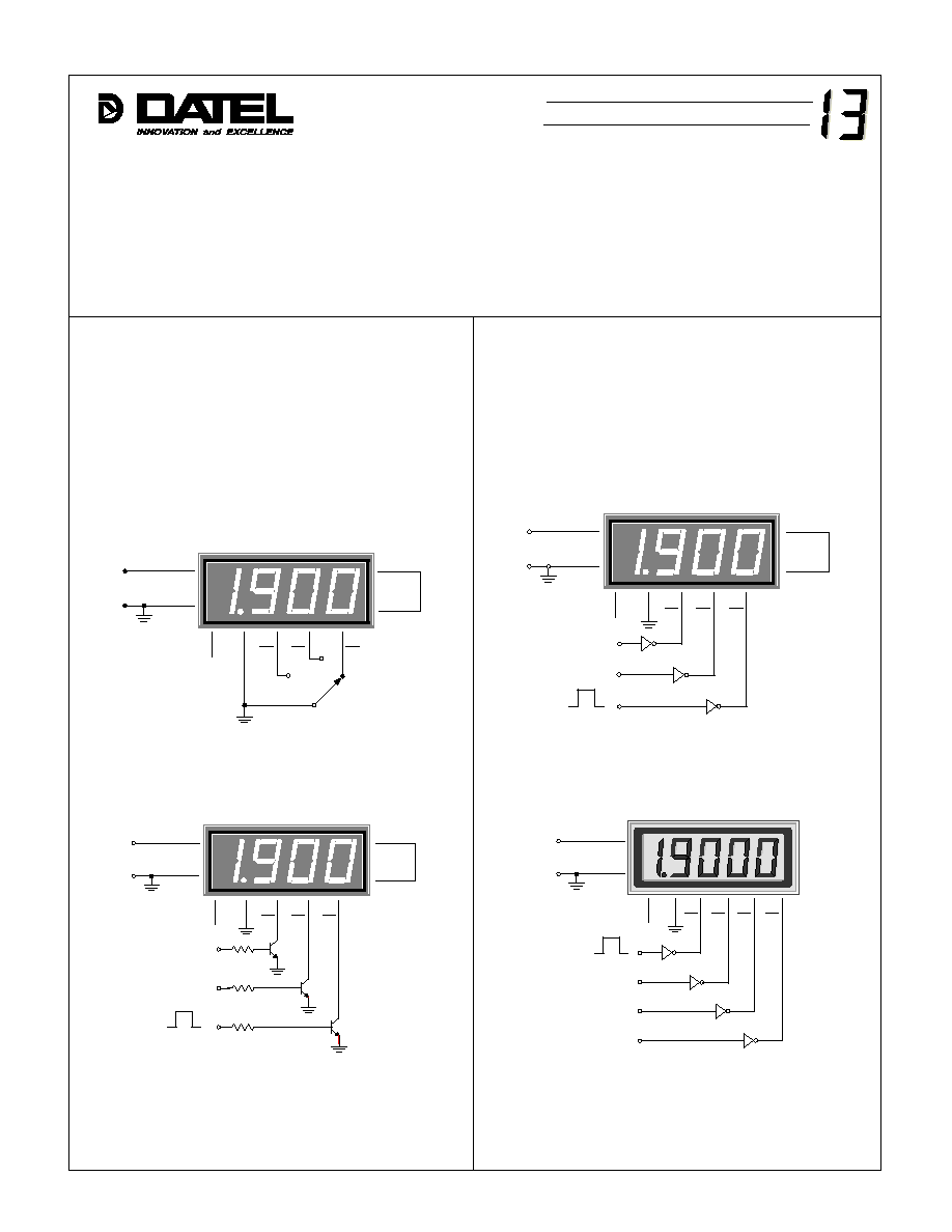
Figure 3. Inverting gate decimal point drivers usable with
5V-powered 3Ω digit DMS panel meters
except models with blue LED displays.
Figure 4. Inverting gate decimal point drivers usable with
5V-powered 4Ω digit LCD and DMS-40PC-X-RL
(low-power red LED's) panel meters.
Figure 2. NPN transistors can be used with all
5V-powered, 3Ω and 4Ω digit, DMS panel meters.
Figure 1. Simple selector switch can be used with
all DMS Series panel meters.
Decimal Point Drivers
Other components that can be used for decimal point drivers,
particularly when dynamic control is required, are TTL or CMOS-
compatible logic gates/buffers and open-collector/open-drain
discrete transistors. The maximum current the driving device must
sink is 20mA (see individual product data sheets for more specific
data). The following diagrams illustrate the various techniques that
can be used for driving the decimal points on all DMS Series
meters.
The most common technique for activating a single decimal
point is simply tieing its activation pin to ground. In most situations,
only one decimal point is used because the display reading
represents only one parameter. However, some applications require
the use of more than one decimal point in order indicate a different
range, or perhaps, have the reading represent some other system
parameter. A simple rotary switch can be used with any DMS meter
when two or more different decimal point selections are required.
The rotary switch method is illustrated in Figure 1.
1
12
3
+5V SUP
(≠) IN LO
GND
11
(+) IN HI
6
DP1
+
≠
V
IN
DMS-30PC
8
7
REF OUT
REF IN
4
5
DP2
DP3
1
12
3
+5V SUP
(≠) IN LO
GND
11
(+) IN HI
+
≠
V
IN
DMS-30PC
8
7
REF OUT
REF IN
4
5
DP2
DP3
U1A
U1 = 74LS04
U1B
U1C
+5V (ON)
0V (OFF)
6
DP1
1
12
3
+5V SUP
(≠) IN LO
GND
11
(+) IN HI
6
DP1
+
≠
V
IN
DMS-30PC
8
7
REF OUT
REF IN
4
5
DP2
DP3
4.7k
4.7k
4.7k
Q1
Q2
Q3
Q1-Q3
2N2222
+5V (ON)
0V (OFF)
1
12
3
+5V SUP
(≠) IN LO
GND
11
(+) IN HI
+
≠
V
IN
DMS-40LCD-X/X-5
8
5
DP2
DP4
U1A
U1 = 74LS04
U1B
U1C
U1D
4
DP3
+5V (ON)
0V (OFF)
6
DP1
Æ
Æ
DMS APPLICATION NOTE
