DATEL, Inc., Mansfield, MA 02048 (USA)
∑
Tel: (508)339-3000, (800)233-2765 Fax: (508)339-6356
∑
Email: sales@datel.com
∑
Internet: www.datel.com
DATEL makes no representation that the use of its products in the circuits described herein, or the use of other technical information contained herein, will not infringe upon existing or future patent rights. The descriptions contained
herein do not imply the granting of licenses to make, use, or sell equipment constructed in accordance therewith. Specifications are subject to change without notice. The DATEL logo is a registered DATEL, Inc. trademark.
Troubleshooting Guide
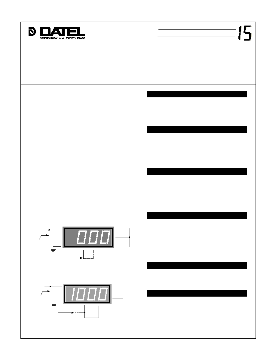
Figure 2. Self-Test Circuit (Reference Test)
Figure 1. Self-Test Circuit (Zero Test)
Though panel meters are not very complex components, the
real-world situations in which they are used are not always that
straightforward. Though we have attempted to clearly describe a
number of the more popular DPM applications, it is inevitable that
your particular application will have its own little idiosyncracies and
challenges.
The following troubleshooting guide -- while obviously not
guaranteed to solve every problem -- should prove useful,
particularly to first-time users of DATEL's DMS Series DPM's.
Where applicable, we have referenced DATEL Application Notes
that may provide additional clarifications, alternatives or other
helpful insights. The most likely "possible causes" of a particular
problem are listed first with the least likely ones listed later.
Some simple "self-tests" are also included to assist in
determining whether or not a meter has suffered irreparable
damage (i. e., "blown"). The self-tests are particularly useful if dc
voltage calibrators, digital multimeters (DMM's), or similar
troubleshooting instruments are not readily available. Testing is
usually more effectively performed with the meter disconnected
from the circuit in question.
If problems persist, please don't hesitate to call DATEL's
experienced application engineers at either 508-339-3000 or
800-233-2765.
Display will not read "000"
Erratic (unsteady) readings
All readings low
Display intermittently overranges
Display permanently overranged
Dead (off) display
1.
There may be ground loops in the input/power system wiring.
2.
Pin 10 (ANALOG COMMON) may be incorrectly tied to pin 3
(5V RETURN)(DMS-40PC).
3.
Power source may be poorly regulated.
4.
Input signal may have excessive ac components.
5.
There may be strong magnetic or electrostatic fields near the meter.
See application note 2.
1.
Power may be connected incorrectly (reverse polarity?).
Verify connections at meter with a DMM.
2.
On DMS-20PC models, pin 2 (DISPLAY ENABLE) may be open.
3.
Meter may be blown or defective (see self-tests).
See individual product data sheets.
1.
Pin 7 (REFERENCE IN) may be open (DMS-20/30 only).
2.
9V models may be incorrectly used in single-ended mode.
3.
Input voltage range may be exceeded.
4.
Common mode voltage may exceed power supply voltage.
5.
Meter may be blown or defective (see self-tests).
See application notes 2 and 3.
1.
Pins 11 and/or 12 (INPUTS) may be open (no connections).
2.
Input signal may be "floating". For 5V models, tie pin 12
(≠INPUT LO) to pin 3 (5V RETURN). For 9V models,
tie pin 12 to pin 10 (ANALOG COMMON).
3.
Input may not be a steady dc voltage.
4.
Pin 7 (REFERENCE IN) may be open (DMS-20/30 only).
See individual product data sheets & ap notes 2, 3 and 11.
1.
Pin 10 (ANALOG COMMON) may be grounded (DMS-20's only).
2.
Pin 9 (+1.23V REFERENCE OUT) may be incorrectly tied to pins 7
and 8 (REFERENCE IN/OUT) (DMS-30's only).
3.
Pin 8 may be incorrectly tied to pin 7 (DMS-40's).
4.
Gain potentiometer on back of meter may be misadjusted.
5.
Wrong input range (too high) possibly being used.
6.
Wrong input range may have been selected (DMS-40LCD only).
See application notes 3 and 4.
1.
Input may not be at 0.0V (has some zero offset).
2.
There may be ground loops in input signal wiring.
See application notes 2, 3 and 12.
2
3
+SUPPLY
Connect
only on
DMS-20PC
8
7
11
12
10
Connect only on DMS-20 and DMS-30
(≠) IN LO
(+) IN HI
ANA COMM
REF OUT
REF IN
RET
DISP EN
1
Connect only on
DMS-20 and DMS-30
2
3
+SUPPLY
Connect
only on
DMS-20PC
8
7
1
11
12
10
(≠) IN LO
(+) IN HI
ANA COMM
REF OUT
REF IN
RET
DISP EN
Æ
Æ
DMS APPLICATION NOTE