DATEL, Inc., Mansfield, MA 02048 (USA)
∑
Tel: (508)339-3000, (800)233-2765 Fax: (508)339-6356
∑
E-mail: sales@datel.com
∑
Internet: www.datel.com
DATEL makes no representation that the use of its products in the circuits described herein, or the use of other technical information contained herein, will not infringe upon existing or future patent rights. The descriptions contained
herein do not imply the granting of licenses to make, use, or sell equipment constructed in accordance therewith. Specifications are subject to change without notice. The DATEL logo is a registered DATEL, Inc. trademark.
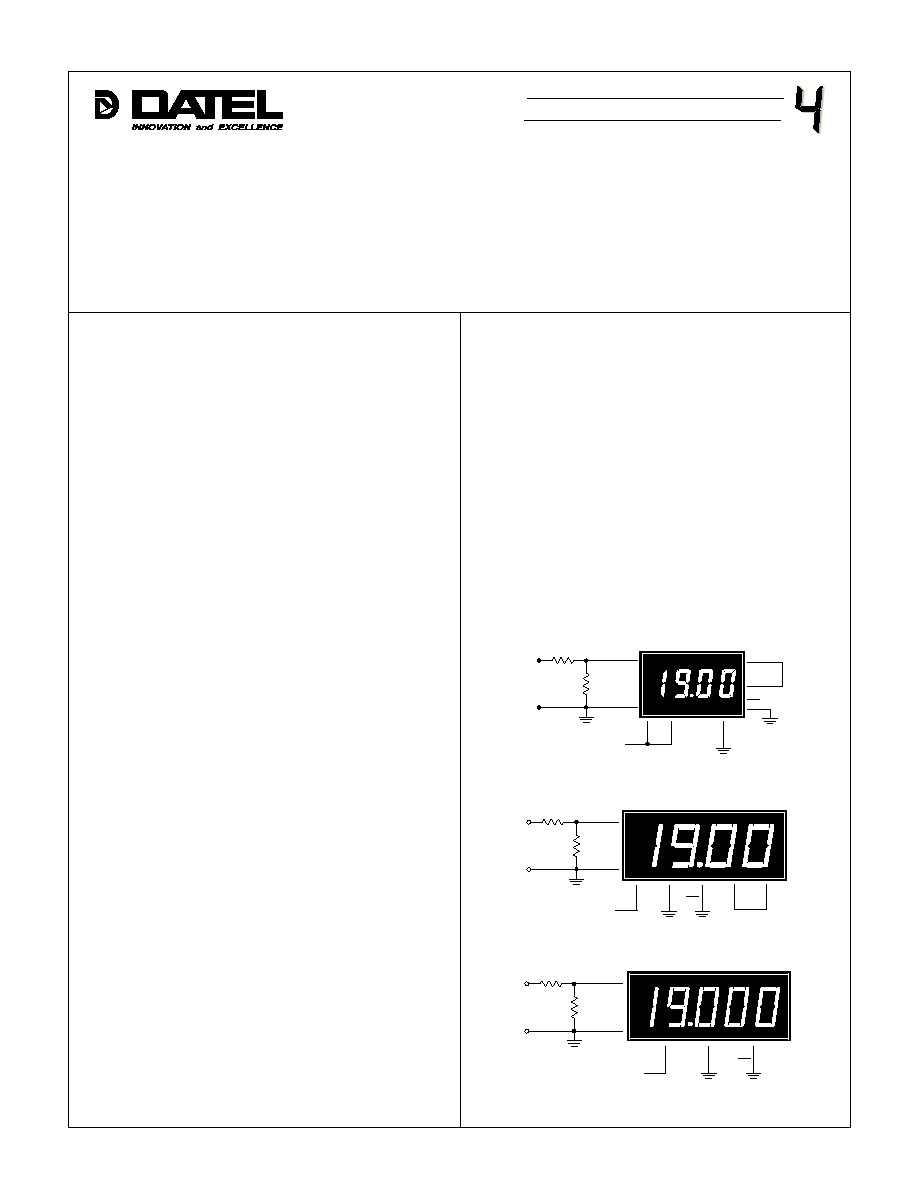
Figure 1. DMS-20PC-1
Figure 2. DMS-30PC-1
I
ntroduction
It is oftentimes necessary to attenuate "large" input signals
down to a level that more closely matches the input range of a
selected meter. For example, suppose the signal to be measured is
19 Volts, and the input voltage range of the available meter is 2 Volts
(the preferred model for any attenuation circuit). Obviously, the "raw"
input signal voltage is much too high for a ± 2V meter to measure
directly and must first be attenuated.
The attenuation techniques and required connections for DMS-
20-1, DMS-30-1 and DMS-40-1 meters are shown in Figures 1, 2
and 3. The recommended resistance value for R1 is 909k
. This is
necessary in order to prevent excessive loading of the circuit
producing the voltage (V
IN
) being measured.
10:1 Attenuator
For this example, assume the desired display reading is "1900"
for an applied input (V
IN
) of 19 Volts. Under these conditions, the
actual input to the meter (E1) must first be reduced to 1.900 Volts. If
V
IN
and E1 are known, and assuming a value of 909k
for R1, the
value for R2 can be calculated from the following equation:
when V
IN
equals 10 Volts. In order to have a reading of "600", the
actual required input applied to the meter (E1) must be attenuated to
0.60 Volts. Knowing that V
IN
= 10V, E1 = 0.6V, and assuming a value
for R1 of 909k
, R2 can now be calculated:
The value of 58.021k
is not a standard ±1% resistor; the
closest value is 57.6k
. Using a 57.6k
resistor for R2 gives a
value for E1 of 0.595 Volts which is very close to the desired voltage
of 0.6 Volts. Adjustment of the gain of the meter will be required for
the display to read exactly "600" for the 10V input.
For additional information on selecting and using 1% resistors,
see the application notes "Selecting 1% Resistors" and "Component
Suppliers Listing".
R2 = (E1 x R1) / (V
IN
- E1)
R2 = (0.6V x 909,000) / (10 - 0.6V)
R2 = 58.021k
Figure 3. DMS-40PC-1
R2 = (E1 x R1) / (V
IN
- E1)
R2 = (1.9V x 909,000) / (19 -1.9)
R2 = 101k
Unfortunately, the above values for R1 and R2 do not attenuate
the input to the exact desired voltage of 1.900 Volts. However, if one
starts with the calculated values for R1 and R2, the display can then
be changed to the desired reading of "1900" by adjusting the
calibration potentiometer located on the back of the meter. This
example is for illustrative purposes only. A 10:1 attenuation is
already built-in on all ±20V DMS Series meters (-2 models), and
they should be used whenever possible.
Attenuator Ratios Other Than 10:1
In real-world applications, the required attenuation ratio can
have many different values other than 10:1 or 100:1, etc. For
example, suppose we want the display to indicate "600" pounds (lb.)
E1 = (V
IN
x R2) / (R1 + R2)
E1 = (19 x 100k) / (909,000 + 100,000)
E1 = 1.883 Volts
The closest ±1% resistor value for R2 is 100k
.
If V
IN
= 19V, R1 = 909k
and R2 = 100k
, the actual voltage at
the meter's inputs (E1) is equal to:
Engineering Scaling
12
3
+5V SUP
(+) IN HI
R1
7
8
2
5
DP2
11
R2
V IN
1
E1
+
≠
DIS EN
REF OUT
REF IN
(≠) IN LO
GND
909k
12
3
(≠) IN LO
GND
(+) IN HI
R1
8
7
5
DP2
11
R2
V
IN
1
E1
+
≠
REF
IN
REF
OUT
909k
+5V SUP
12
3
(≠) IN LO
GND
(+) IN HI
R1
5
DP2
11
R2
V
IN
1
E1
+
≠
909k
+5V SUP
Æ
Æ
DMS APPLICATION NOTE
