Direct Current Ammeters
The easiest-to-use shunts have an output that is directly
proportional to the current being measured, i.e., the shunt develops
100mV with 100 Amperes through it. This type of shunt requires no
additional scaling or amplification. A 3Ω digit meter with a 200mV
input range will display "100.0", while a similar 2V-input meter, used
with the same shunt, will display "100".
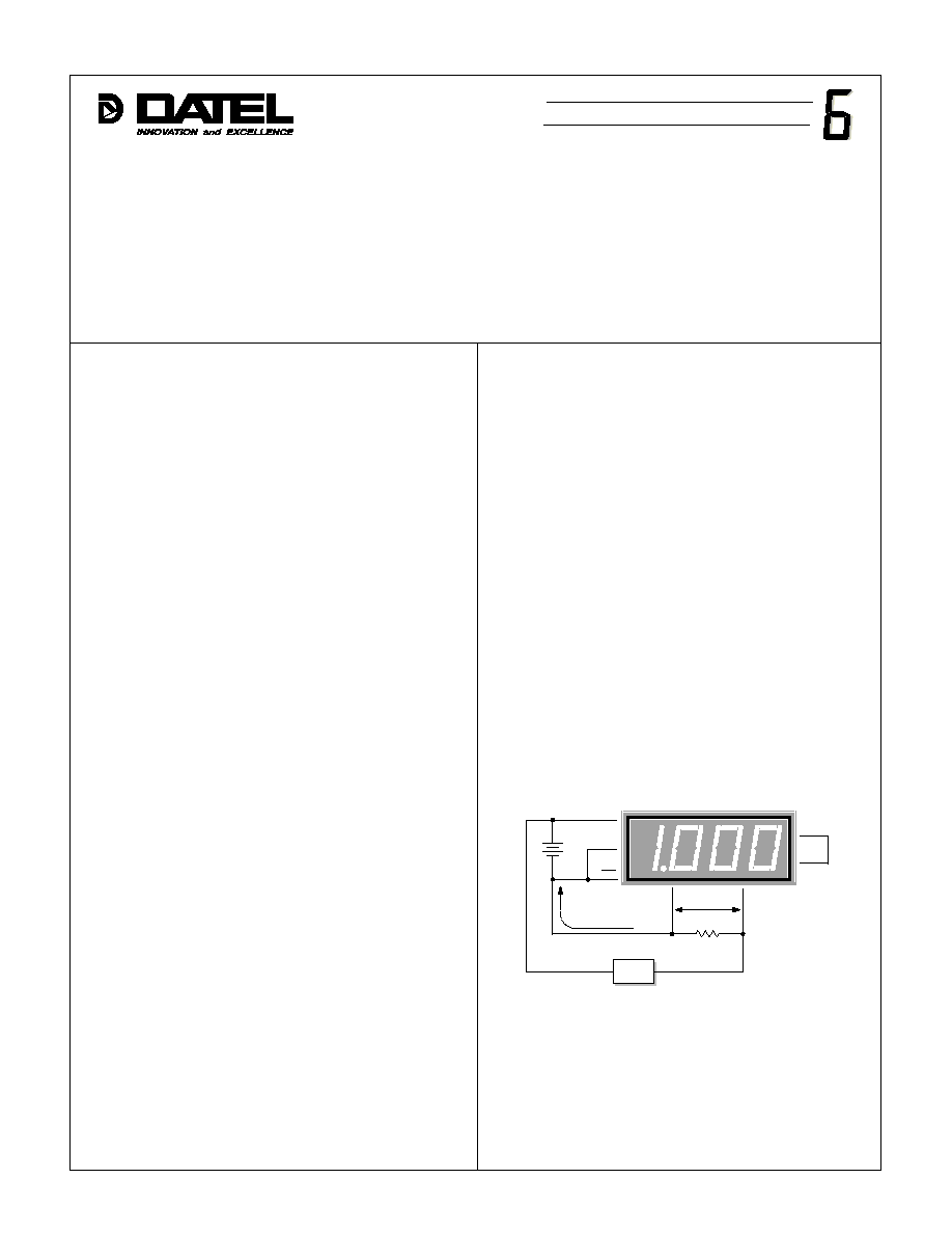
In Figure 1, the 0.1
shunt, with 1.0 Amperes through it, will
develop 0.100Vdc or 100mV across it. The voltage developed across
a shunt is calculated using Ohm's law as follows: the shunt voltage
is equal to the current through the shunt (in Amperes) multiplied by
the shunt's resistance (in Ohms) or V(shunt) = I(shunt) x R(shunt).
Practical Ammeter Examples
The circuit shown in Figure 1, unfortunately, does not depict the
typical real-world ammeter connection scheme which has the
current shunt located in the high side (positive terminal) of the
system power supply. In Figure 1, the voltage across the shunt is
only 0.1Vdc above pin 3 (5V RETURN). This is well below the ±2V
common mode voltage limitation of the meter. Recall that all
voltages at the meter's input terminals are measured with respect
to pin 3.
Introduction
There is a trend to replace older, analog-style readouts with
modern digital displays. As one might expect, the conversion is not
always a trivial task. This is especially true when the conversion
involves older, moving-vane ("pointer" style) analog ammeters. The
typical analog ammeter has only two wires to contend with, and the
required shunt resistor is sometimes built-in to the meter itself. By
comparison, its digital replacement may have as many as five or six
input terminals. The project gets even more complicated when you
include the required external current shunt. Hopefully, after reading
this application note, you will have the necessary information to
avoid the most common pitfalls associated with digital ammeter
installations.
Ammeter Theory
A digital ammeter is basically a very sensitive voltmeter with a
typical input range of ±200mV (a DMS-30PC-0-RS for example). In
order to convert the current to a voltage, the current must first pass
through a device called a current shunt. A current shunt is a low-
value resistor, usually one Ohm or less, that bypasses (or "shunts")
the majority of the current flow around the meter.
Most current shunts have two pairs of terminals: one physically
large pair to carry the load current and another smaller pair to carry
the low-level signal voltage to the meter's input terminals (pins 11
and 12). The low-level signal connections do not require heavy-
gauge wire. 22-26 AWG wire is sufficient since the current flow into
the meter's input is extremely small. However, the load wires must
be carefully chosen so as not to cause excessive heating and/or
voltage drops. In most applications, the load wires also have to meet
strict, electrical-code requirements. Questions on this type of
installation must be referred to qualified personnel only.
Basic Ammeter Example
The circuit shown in Figure 1 illustrates a typical digital ammeter
consisting of a +5Vdc power supply, a 0.1
current shunt, and a
±200mV-input DMS-30PC. The application is to measure the current
supplied to a heater element which consumes one Amperein normal
operation. This configuration poses no common mode voltage
problems -- more on this topic later in this application note --
because the shunt is located in the power supply's ground terminal.
Figure 1. Basic Ammeter Circuit
(Shunt in low side)
DATEL, Inc., Mansfield, MA 02048 (USA)
∑
Tel: (508)339-3000, (800)233-2765 Fax: (508)339-6356
∑
E-mail: sales@datel.com
∑
Internet: www.datel.com
6
3
+
≠
0.1
Current
Shunt
DMS-30PC-0-GS
12
11
0.1V
1
1.0 Ampere
+5V
7
8
+5V
5V RET
DP1
(≠) IN LO
(+) IN HI
REF IN
REF OUT
Load
Æ
Æ
DMS APPLICATION NOTE

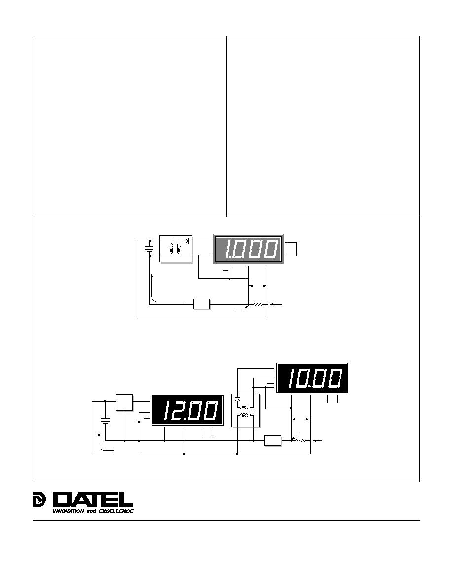
Figure 2. Basic Ammeter Circuit
(Shunt in high side)
Figure 3. Measuring Amperes and Volts
Figure 2 differs from Figure 1 in one very important respect: the
current shunt is located in the high side of the system power supply.
As previously stated, this is the most popular -- and the most
troublesome -- ammeter configuration in use. This type of hookup
requires the use of a DC/DC converter to provide the necessary
isolation between the meter's 5V power source and the system
power supply. If the DC/DC converter is not used, the meter's inputs
((≠)INPUT LO and (+)INPUT HI) will be at, or very close to, +5V. This
condition violates the common-mode voltage limit of ±2V and will
overrange the meter.
12V-Powered Ammeters
As a general rule, all ammeters using high-side current shunts
must use an isolating DC/DC converter. Ignoring this rule could
result in serious damage to the meter, particularly if power system
voltages greater than +6Vdc are used. Systems that use two meters,
one for Amperes, the other for Volts, even if a DC/DC converter is
used, can still be troublesome.
Figure 3 shows the correct connections for a typical two-meter
application. The DC/DC converter is required because the 0.1
current shunt is connected to the positive terminal of the 12V battery.
If the shunt was connected in the negative side of the battery (low
side), both meters could be powered from the LM7805CT regulator.
The DC/DC converter would not be required. Please note that while
the LM7805CT can power as many as 10 DMS-30PC-X-RL (low-
power red LED) meters, it can only supply power to one standard-
intensity DMS-30PC meter.
DMS-EB-DC/DC Application Board
DATEL's DMS-EB-DC/DC application board, with its built-in
DC/DC converter, greatly simplifies the connections required for
ammeters with high-side current shunts. As shipped, the DMS-EB-
DC/DC board will provide an isolated 5V output from a
4.5-5.5V input. If only 12V power is available, the user can easily
install an LM7805CT voltage regulator. See the DMS-EB-DC/DC
data sheet for more information.
6
3
7
8
+
≠
0.1
Current
Shunt
DMS-30PC-0-GS
12
11
0.1V
1
+5V
DC/DC
Converter
+
≠
+5V
5V RET
DP1
(≠) IN LO
(+) IN HI
REF IN
1.0 Ampere
REF OUT
V
OUT
V
IN
+
≠
+4.9V
Load
+5V
5
3
7
8
0.1
Current Shunt
DMS-30PC-0-RL
(Ammeter)
12
11
0.1V
1
DC/DC
Converter
+
≠
5
3
7
8
+
≠
DMS-30PC-2-RL
(Voltmeter)
12
11
1
+12V
LM7805CT
GND
IN
OUT
+5V
5V RET
DP2
(≠) IN LO
(+) IN HI
REF IN
REF OUT
+5V
5V RET
DP2
(≠) IN LO
REF IN
REF OUT
(+) IN HI
V
OUT
V
IN
+
≠
+11.9V
1.0 Ampere
Load
+12V
DATEL, Inc. 11 Cabot Boulevard, Mansfield, MA 02048-1151
Tel: (508) 339-3000 (800) 233-2765 Fax: (508) 339-6356
Internet: www.datel.com Email: sales@datel.com
Data sheet fax back: (508) 261-2857
DATEL (UK) LTD. Tadley, England Tel: (01256)-880444
DATEL S.A.R.L. Montigny Le Bretonneux, France Tel: 01-34-60-01-01
DATEL GmbH M¸nchen, Germany Tel: 89-544334-0
DATEL KK Tokyo, Japan Tel: 3-3779-1031, Osaka Tel: 6-354-2025
DATEL makes no representation that the use of its products in the circuits described herein, or the use of other technical information contained herein, will not infringe upon existing or future patent rights. The descriptions contained herein
do not imply the granting of licenses to make, use, or sell equipment constructed in accordance therewith. Specifications are subject to change without notice. The DATEL logo is a registered DATEL, Inc. trademark.
Æ
Æ

