DATEL, Inc., Mansfield, MA 02048 (USA)
∑
Tel: (508)339-3000, (800)233-2765 Fax: (508)339-6356
∑
Email: sales@datel.com
∑
Internet: www.datel.com
DATEL makes no representation that the use of its products in the circuits described herein, or the use of other technical information contained herein, will not infringe upon existing or future patent rights. The descriptions contained
herein do not imply the granting of licenses to make, use, or sell equipment constructed in accordance therewith. Specifications are subject to change without notice. The DATEL logo is a registered DATEL, Inc. trademark.
V
OUT
= (R1 + R2) (Vcc) (C1) (F
IN
)
V
OUT
= (150 x 10
3
) (7.5) (47 x 10
-9
) (33.33) = 1.762Vdc
The 50k potentiometer is adjusted so the meter's display
reads "1999" at 1999 RPM
.
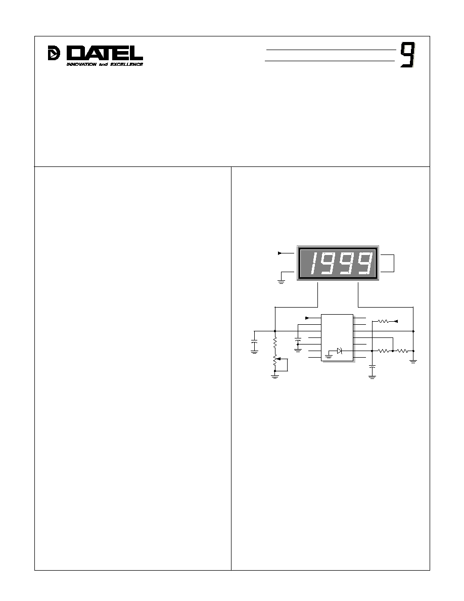
General Description
The circuit shown in the figure below will have a display reading
of "1999" for an input frequency of 33.33Hz (equivalent to 1999
rpm). The 0.047µF capacitor (C1) should have a low-temperature-
coefficient dielectric (polyester, polycarbonate and polypropylene
are adequate for most applications). The 47µF capacitor (C2) is
used to reduce the output ripple of the LM2917. If this value is made
too large, the output ripple will be smaller, however, the response
time of the LM2917 output (pin 3), for a given change in F
IN
, will be
longer. The 50k multi-turn potentiometer allows for overall
calibration of the circuit's output at 1999 rpm. All fixed resistors
should be metal-film types for good temperature stability.
Theory of Operation
The equation below is used to determine the LM2917's output
voltage (pin 3) which is connected to the DMS-30PC's (+) INPUT HI
terminal (assume the 50k potentiometer is set to 0
)
:
The differential inputs of the LM2917 (pins 1 and 11) give the
user the option of setting the input signal triggering level while still
maintaining hysteresis around that point for noise rejection. In this
example, this function is achieved with the 10k
and 200
resistor
divider (R4 and R5). Pins 1 and 11 of the LM2917 should not be
taken below ground or above the supply voltage on pin 9 (+7.5V).
To ensure proper input frequency sensing, the voltage applied to pin
11 of the LM2917 should be at least 100mV above the lowest input
voltage normally applied to pin 1 (F
IN
). Please refer to the LM2917
data sheet (available from National Semiconductor) for more
information.
Figure 1. 0-1999 RPM Tachometer Circuit
2000 RPM Tachometer
DMS-30PC-1-GS
R1
2
150k
R2
50k
47µF
+
C1
0.047µF
F IN
1
3
4
5
6
7
13
14
12
11
10
9
8
7.5V
LM2917
R3
470
+12V
R4
10k
R5
200
10µF
16V
+
12
11
1
+5V
3
GND
7
8
C3
C2
REF OUT
REF IN
(+) IN HI
(≠) IN LO
Æ
Æ
DMS APPLICATION NOTE