Features
∑∑
∑∑
∑
Displays true rms values of ac inputs
∑∑
∑∑
∑
±0.5% accuracy for DMS-30PC-0
or DMS-30LCD-0-5
∑∑
∑∑
∑
±2% accuracy for DMS-30PC-1
or DMS-30LCD-1-5
∑∑
∑∑
∑
Also works with DMS-40PC/LCD meters
(see Ap Note 11)
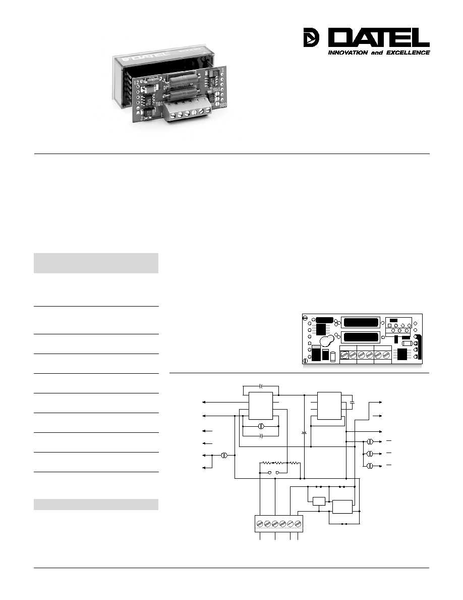
AC-to-RMS Converter
Application Board for
DMS-30PC/LCD Meters
DMS-EB-RMS
Ordering Information
DMS-EB-RMS
AC-to-RMS conversion
board
DMS-BZL1
Bezel assembly
DMS-BZL2
Bezel assembly with
sealing gasket
Functional Specifications
(T
A
= +25∞C, V
CC
= +5V)
Vac Measurement Range:
±200mV meters
0 to 199.9Vac
±2V meters
0 to 750Vac
Conversion Accuracy:
0-200Vac
±0.5%
0-750Vac
±2%
Crest Factors
3, maximum
Input Frequency Range
40Hz to 2kHz
Primary Operating Power
+5V (±5%)
Current Consumption (Board only)
+0.5mA typ., +1mA max.
Operating Temperature Range
0 to +60∞C
Storage Temperature Range
≠20 to +75∞C
Humidity
0 to 95%, non-condensing
Dimensions
2.02" (51.31mm)W x 0.83" (21.08mm)H
Figure 1. DMS-EB-RMS Schematic Diagram
Actual Size
DS-0398A 1/98
Technical Notes
Description: The DMS-EB-RMS board allows the true rms value of ac signals to be displayed
on 5V-powered DMS-30PC/LCD digital voltmeters. The meter/board combination has an input
range of 0-750Vac with ±2V meters (1Vac resolution) or 0-199.9Vac with ±200mV meters
(0.1Vac resolution). A built-in screw-terminal block reliably interfaces signal and power
connections. The DMS-EB-RMS now accommodates user-installed modifications such as
input-scaling resistors and isolated +5V dc/dc converters.
Power and Safety Precautions: The DMS-EB-RMS's AC HI and AC LOW inputs are not
electrically isolated from its 5V supply (AC LOW is connected directly to 5V RETURN).
When measuring any input signal which is derived from ac power mains, a dedicated (i.e.,
it only powers the DMS-EB-RMS), transformer-isolated +5V supply, with a minimum 1kV
breakdown rating, must be used to power the DMS-EB-RMS board/meter combination.
When measuring ac power mains inputs, never connect the DMS-EB-RMS's 5V RETURN
to chassis/earth ground anywhere in the system. Failing to follow these instructions could
defeat any safety grounding and will place the system +5V power supply, and all its
associated circuitry, at dangerously elevated ac-line potentials. In many applications, the
DMS-EB-RMS installation is required to meet
electrical code requirements. To ensure
safe operation, the DMS-EB-RMS board
should only be installed and serviced by
technically-qualified personnel. See DMS
Application Note 11 for more details.
(≠) INPUT LO
(+) INPUT HI
REF. OUT
REF. IN
1
5
6
3
+5V
5V Return
TB1
CAV
OUT
+V
S
COM
≠V
S
CF
V
IN
CC
V
OUT
LV
OSC
V+
CAP≠
GND
CAP+
BOOST
SG1
SG2
SG3
5V RETURN
DP3
DP2
DP1
+5V SUPPLY
C5
2.2µF
+
+
R1
988k
R2
988k
R3
1.98k
+
C2
10µF
C1 100µF
+
1
2
3
4
5
6
7
8
5
6
7
8
1
2
3
4
U1
U2
AC HI
3
4
5
6
1
2
SG4
J1
12
11
8
7
10
9
JP1
J6
GND 2
1
3
U3
Q
PS1
Q
1
2
3
4
C4
2.2µF
J4
J5
AC LOW
Components are user-supplied
and not part of the standard product.
DC/DC
≠V
+V
+V
IN
≠V
OUT
V
IN
V
OUT
Q
Æ
Æ
DATEL, Inc., Mansfield, MA 02048 (USA)
∑
Tel: (508)339-3000, (800)233-2765 Fax: (508)339-6356
∑
Email: sales@datel.com
∑
Internet: www.datel.com
DATEL makes no representation that the use of its products in the circuits described herein, or the use of other technical information contained herein, will not infringe upon existing or future patent rights. The descriptions contained
herein do not imply the granting of licenses to make, use, or sell equipment constructed in accordance therewith. Specifications are subject to change without notice. The DATEL logo is a registered DATEL, Inc. trademark.
R 1
R 2
R 3
U 2
1 2
1
C 4
1
S G 4
S G 3
U 1
P S 1
J 1
U 3
J P 1
J 6
2
C 2
C 1
C 5
J 4
T B 1
J 5
SG
1
SG
2
J 2
J 3
1
2
3
4
5
6
1 1
1 0
9
8
7
Purchase on-line at www.datel.com