 | –≠–ª–µ–∫—Ç—Ä–æ–Ω–Ω—ã–π –∫–æ–º–ø–æ–Ω–µ–Ω—Ç: DMS-PS-CM | –°–∫–∞—á–∞—Ç—å:  PDF PDF  ZIP ZIP |

DATEL, Inc., Mansfi eld, MA 02048 (USA)
∑
Tel: (508)339-3000, (800)233-2765 Fax: (508)339-6356
∑
E≠mail: sales@datel.com
∑
Internet: www.datel.com
C
Æ
US
E151252
85-264Vac or 110-340Vdc
Universal Input
DMS-PS-CM Series
DATEL's DMS-PS-CM Series of high-effi ciency, chassis mount AC/DC power sup-
plies feature low noise (40mV on main, 8mV on auxiliaries), fully-isolated +24, +12V,
and +5V outputs, making them perfect for powering today's complex instrumentation.
A high-current main output is isolated from the AC line by 3000Vac. In dual- and triple-
output models, the low-current auxiliary outputs are isolated from the main output by
1000Vdc, and from each other by 2000Vdc, effectively providing double isolation from
the AC line! This unprecedented isolation eliminates ground loop problems in complex,
multiple-instrument applications.
Full-load effi ciencies of up to 80% and output-power ratings of 5, 10 or 16
Watts, combine to ensure minimal ac power consumption. For intermittent use or low-
power applications, the 5-Watt model's no-load quiescent consumption with a nominal
120Vac input is a mere 0.6 Watts---that's nearly seven times less than a standard
4W night light! These low cost, high-effi ciency power supplies can signifi cantly reduce
long-term electricity costs in low (<5Watts) to medium (<16Watts) power applications.
All DMS-PSX-CM power supplies feature universal inputs of 85-264Vac 50/60Hz,
built-in line fuses, and on-board `Power On' LED indicators. At full rated load, hold-up
time is typically 20ms at 120Vac, and 80ms at 230Vac. All outputs provide indefi nite
short-circuit protection and, for added reliability, the main high-current output also
includes overvoltage protection. A rugged, vibration-proof, chassis mount package
incorporates large, shock-resistant terminal blocks for all I/O connections.
Multiple outputs, low noise, low cost, high effi ciency, double isolation, and rugged
construction combine to make DMS-PSX-CM Series AC/DC power supplies the ideal
choice for powering today's sensitive instrumentation, and any electronic device that
requires a reliable dc voltage!
High Effi ciency, AC/DC
Instrumentation Power Supplies
with Individually Isolated Outputs
Features
Æ
Æ
∑
Up to 80% effi cient single, dual, and triple-
output models
∑
Individual, fully-isolated outputs:
3000Vac on main
4000V double-isolation on auxiliaries
∑
Available with +5V, +12V, and +24V outputs
∑
Low noise: 40mVp-pk on main, 8mVp-pk on
auxiliaries; Ideal for sensitive instrumentation
∑
Universal input: 85-264Vac @ 47-63Hz or
110-340Vdc
∑
Choice of 5, 10, or 16W models for minimal
system power-consumption
∑
Standby power consumption as low as 0.6W
∑
Short-circuit protection on all outputs;
OVP on main output
∑
Built-in ac mains fuse & 'Power On' indicator
∑
5W models operate up to 5 LED-display DPM's
∑
Vibration-resistant, chassis-mount
modular packages
∑
EMI compliant; Safety approvals pending
Figure 1. DMS-PS-CM Series Simplifi ed Schematic
TB4
F1
1A/250V
TB1
LDO
Regulator
DC/DC
Converter
IN
OUT
GND
AC(L)
AC(N)
FG
+
V1
≠
TB2
+
V2
≠
LDO
Regulator
DC/DC
Converter
AC/DC Converter
(Auxilliary)
(Auxilliary)
(Main)
IN
OUT
GND
TB3
+
V3
≠
+
+
+
+
+
+
+
+
+
≠
≠
≠
≠
**
*
**
**
Used only on dual and triple-output models
*
Not used on single-output models
85-264Vac
@ 50/60Hz
or
110-340Vdc
H I G H E F F I C I E N C Y , A C / D C I N S T R U M E N T A T I O N P O W E R S U P P L I E S
DMS-PS-CM Series
2
DATEL, Inc., Mansfi eld, MA 02048 (USA)
∑
Tel: (508)339-3000, (800)233-2765 Fax: (508)339-6356
∑
E≠mail: sales@datel.com
∑
Internet: www.datel.com
Performance/Functional Specifi cations
Typical at T
A
= +25∞C and V
IN
= 85-264V @47-63Hz
All models will also operate from a regulated and fi ltered 110 to 340Vdc input.
Unless otherwise specifi ed, load regulation is measured with the output under
test undergoing a load change of 100% to 50% at nominal line input and, when
applicable, with all other outputs operating at 50% of rated load.
Transient response is defi ned as the output returning to within its specifi ed
tolerance in 10ms or less, following a 90% load change.
AC Input
Input Voltage Range, All models
85-264V @47-63Hz
Input Current (115V/230V, typ.):
5-Watt
Models
0.15A/0.07A
10-Watt
Models
0.3A/0.13A
16-Watt
Models
0.33A/0.16A
Inrush Current (All models, typical peak):
@115Vac
14.1A
@230Vac
32.5A
Isolation (Min.):
Output V1 to AC Input
3000Vac
Outputs V2 & V3 to AC Input
3000Vac + 1000Vdc
AC Input to Frame Ground
1500Vac
Output
V1
to
Frame
Ground
500Vac
Outputs V2 & V3 to Frame Ground
500Vac + 1000Vdc
Outputs V2 & V3 to Output V1
1000Vdc
Output V2 to Output V3
2000Vdc
Frame Ground Leakage Current (Max.):
@115Vac
0.5mA
@230Vac
3.5mA
Switching Frequency (Typical):
V1
(5W and 10W models)
75kHz
V1
(16W models)
83kHz
V2
&
V3
(All models)
100kHz
Line Fuse (Built-in)
1A/250Vac, 5 x 20mm, meeting
IEC60127-2, sheet 3 specifi cation
for time lag fuses (slow-blow)
AC Mains Terminal Block (TB4):
Wire Size & Type
14-20AWG (2.5 to 0.5mm
2
),
solid or stranded
Insulation
Strip
Length
0.25 inches (6.4mm)
Screw
Tightening
Torque
4.4 pound-inches (0.5Nm)
Rated
Voltage
630V (VDE 0110-V. Group 2);
250V (VDE 0110-V. Group 3)
EMI (All models)
Meets CISPR Pub. 22 & FCC
Class
B
Safety Approvals
Pending
DC Outputs
Line Regulation (All outputs)
±0.1% (max)
Load Regulation:
V1
(All models)
±2%
V2
&
V3
(All models)
±0.2% (max)
Output Accuracy (Max.):
V1
(All models)
±2.0%
V2
&
V3
(All models)
±2.5%
Hold-Up Time (47-63Hz):
@115Vac
20mSec. typ.
@230Vac
80mSec. typ.
Noise & Ripple
(All models, 20MHz bandwidth):
See Noise & Ripple graphs
V1
40mVp-pk (typ.)
V2
&
V3
8mVp-pk (typ.)
Transient Response
See Transient Response graphs
DC Outputs
(continued)
Effi ciency (Typ.@ 120Vac, full load):
Single Output Models
75%
Dual
Output
Models
73%
Triple
Output
Models
71%
DC-Output Terminal Blocks (TB1, TB2, TB3):
Wire
Size
&Type
16-20AWG (1.5 to 0.5mm
2
),
solid or stranded
Insulation
Strip
Length
0.25 inches (6.4mm)
Screw
Tightening
Torque
3.6 pound-inches (0.4Nm)
Short Circuit Protection (All outputs)
Foldback, self-recovering
Overvoltage Protection V1 (max.)
134% x Vout
Environmental
Operating Temperature
0 to +50∞C @ full rated power;
≠25 to +70∞C @ 50% rated power
(see
Figure
3)
Storage Temperature
≠40 to +85∞C
Cooling
Free air convection with derating
(see Figure 3 and Technical
Notes)
Humidity (Non-condensing)
0 to 85%
Physical
Dimensions
See Mechanical Specifi cations
Weight:
5
Watt
Models
5.8 ounces (165 grams)
10
Watt
Models
6.9 ounces (195 grams)
16
Watt
Models
7.9 ounces (223 grams)
Case Materials:
Outer
Case
ABS, UL94 5VA
DC/DC
Modules
Phenolic, UL94 V-0
AC/DC
Modules
Plastic, UL94 V-1
H I G H E F F I C I E N C Y , A C / D C I N S T R U M E N T A T I O N P O W E R S U P P L I E S
DMS-PS-CM Series
3
DATEL, Inc., Mansfi eld, MA 02048 (USA)
∑
Tel: (508)339-3000, (800)233-2765 Fax: (508)339-6356
∑
E≠mail: sales@datel.com
∑
Internet: www.datel.com
Tehnical Notes
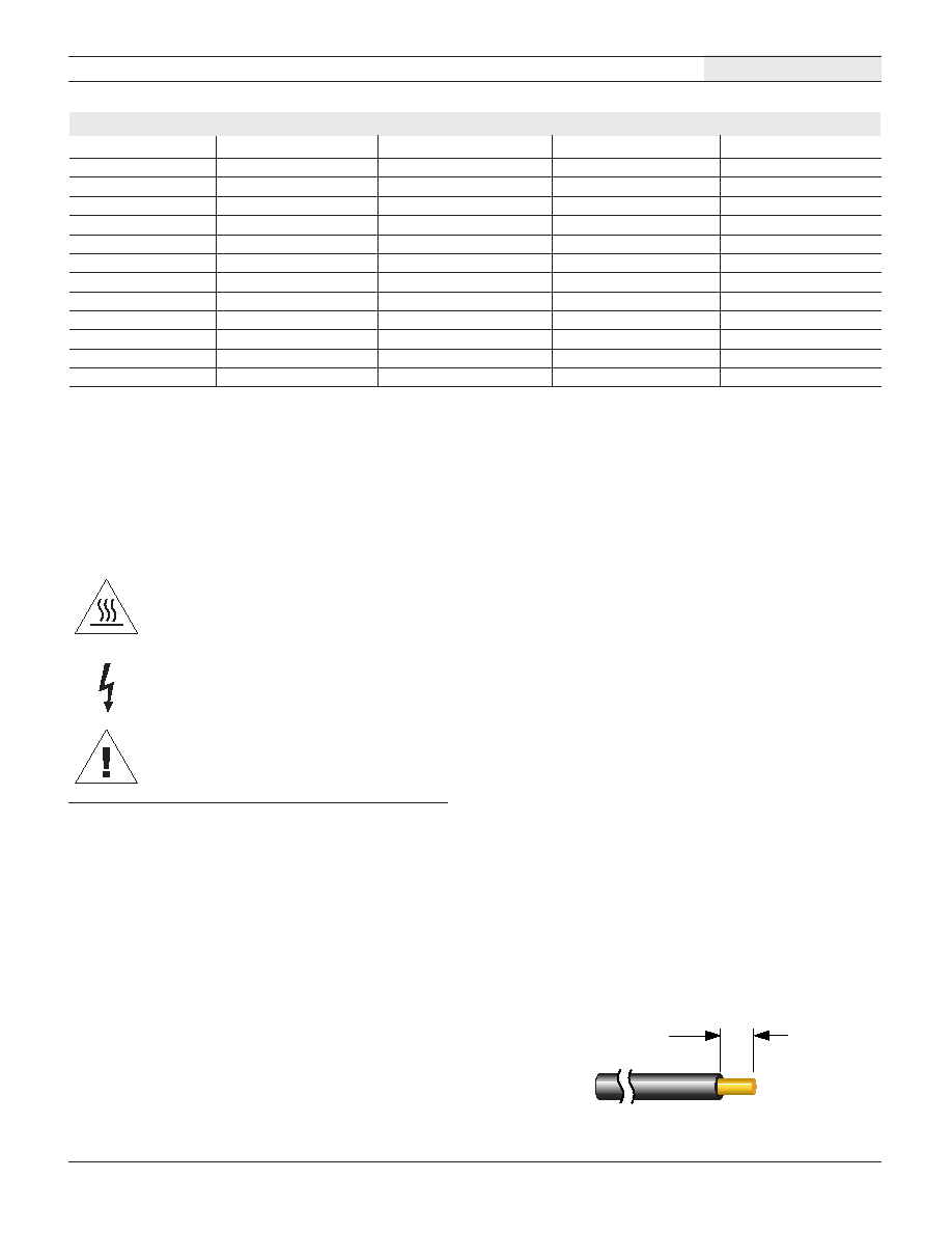
Ordering Information and Selection Guide
DATEL Part No.
Rated Power
V1 Output
V2 Output
V3 Output
DMS-PS1-CM
5 Watts
5Vdc/1A
--
--
DMS-PS2-CM 5
Watts 5Vdc/0.65A
4.85Vdc/0.2A
--
DMS-PS3-CM 5
Watts 5Vdc/0.35A
4.85Vdc/0.2A
4.85Vdc/0.2A
DMS-PS4-CM
10 Watts
24Vdc/0.45A
--
--
DMS-PS5-CM 10
Watts 24Vdc/0.35A
4.85Vdc/0.2A
--
DMS-PS6-CM 10
Watts 24Vdc/0.30A
4.85Vdc/0.2A
4.85Vdc/0.2A
DMS-PS7-CM
16 Watts
24Vdc/0.70A
--
--
DMS-PS8-CM 16
Watts 24Vdc/0.60A
4.85Vdc/0.2A
--
DMS-PS9-CM 16
Watts 24Vdc/0.55A
4.85Vdc/0.2A
4.85Vdc/0.2A
DMS-PS10-CM
16 Watts
12Vdc/1.35A
--
--
DMS-PS11-CM 16
Watts 12Vdc/1.2A 4.85Vdc/0.2A
--
DMS-PS12-CM 16
Watts 12Vdc/1.2A 4.85Vdc/0.2A
4.85Vdc/0.2A
1. Shock Hazard: DMS-PS-CM Series power supplies feature touch-
proof terminals blocks and fully-isolated plastic construction, thereby
greatly reducing the risk of electrical shock. However, these are mains-
powered devices whose operation is derived from hazardous and
potentially lethal voltages.
All service and installation must be performed by qualifi ed personnel,
with the ac supply voltage de-energized. Before making connections to
any of the unit's terminal blocks, use a digital voltmeter to verify that the
ac supply is de-energized (off).
2. AC Supply Fuse (F1): All DMS-PS-CM Series power supplies are
equipped with a built-in 1A/250V time-lag fuse. Replacement fuses
must be of the same type and rating; please refer to the Functional
Specifi cations section of this datasheet for more information. F1 is
conservatively rated in order to reduce nuisance tripping which might
occur during power-up or output overload conditions. However, F1 is
primarily intended to provide protection in the event of catastrophic
failure in the DMS-PS-CM's ac/dc converter.
IMPORTANT! To ensure safe and reliable operation, DMS-PS-CM
power supplies must be installed and serviced by qualifi ed per-
sonnel. Contact DATEL if there is any doubt regarding their instal-
lation and/or operation. Please read all of the following technical
and application notes BEFORE installing or making connections
to DMS-PS-CM power supplies.
3. Fuse Replacement: If any dc-output drops to zero volts, and no fault
conditions exist within the external load circuitry or the ac mains, F1
may have failed. F1 is located on the circuit (etch) side of the pc-board.
Fuse replacement is performed by fi rst de-energizing and then discon-
necting the ac mains from TB4. Next, disconnect all load wiring from
TB1, TB2, and TB3. Lastly, remove the four screws that secure the
pc-board to the plastic case. After making sure that the new fuse is
securely attached to its mounting clips, re-assemble the unit using all
four screws. Reconnect all input and output wiring and re-apply ac
power.
If the unit still does not operate properly, and the ac supply at TB4 is
measured to be within its specifi ed operating range, the power supply
is defective and must be replaced. Except for F1, DMS-PS-CM supplies
contain no other user-serviceable components.
4. Wire Gauges and Fusing: All wiring connected to the DMS-PS-CM's
terminal blocks must meet the requirements specifi ed in the Functional
Specifi cations section. All ac supply and load wiring must be rated
for the voltages and currents they will conduct and must comply with
any code or application-mandated requirements pertaining to the user's
specifi c installation. Applications subject to vibration should include
adequate strain reliefs on both input and output wiring. Install the strain
reliefs within 2-3 inches (5-7.5cm) of the terminal blocks.
It is recommended that all wiring be rated for 600V and 105∞C opera-
tion (UL1015 type, for example). Also, wire insulation must be stripped
to within ±10% of the dimensions shown in Figure 2. All wires must
be inserted into their respective terminal blocks such that the screw
terminal does not pinch their insulation. No more than two wires
should be connected to any single terminal on TB1 through TB4.
If two wires are attached to a single terminal, be sure to use only two
20AWG (0.5mm
2
) wires on TB1, TB2, and TB3, and only two 18 or
20AWG (0.75 or 0.5mm
2
) wires on TB4.
Dangerous, potentially lethal voltages are present during
normal operation. Disconnect ac mains before servicing.
Reference document: IEC 417, No. 5036.
Caution, refer to accompanying documents for more information.
Reference document: ISO 3864, No. B.3.1.
Caution, unit may become hot in normal operation, thereby creat-
ing a potential burn hazard. Disconnect ac mains and then allow
unit to cool before servicing.
Reference document: IEC 417, No. 5041.
Figure 2. Insulation Strip Length
0.25"
(6.4mm)
Warnings
(Marking)
H I G H E F F I C I E N C Y , A C / D C I N S T R U M E N T A T I O N P O W E R S U P P L I E S
DMS-PS-CM Series
4
DATEL, Inc., Mansfi eld, MA 02048 (USA)
∑
Tel: (508)339-3000, (800)233-2765 Fax: (508)339-6356
∑
E≠mail: sales@datel.com
∑
Internet: www.datel.com
The ac-mains circuit supplying power to DMS-PS-CM supplies must
be fused according to the current rating of the wire gauge used, in
accordance with applicable regulatory codes. The built-in 1ampere line
fuse (F1) only protects the module itself from destructive over currents.
5. AC Mains Connections (TB4): To ensure EMI-compliant operation,
all three ac-supply inputs must be properly connected to TB4. Never
operate any DMS-PS-CM power supply without a ground connection
to TB4's `FG' terminal.
On 120Vac 50/60Hz mains, connect the black or "hot" lead to `AC(L)',
the white or "neutral" lead to `AC(N)', and the supply ground (earth)
to `FG' (Frame Ground). On 220V 50/60Hz ac mains with line and
neutral conductor-designations, connect the line to AC(L), the neutral
to AC(N), and the ground to `FG'.
6. Connector Torque Ratings: It is extremely important to tighten all
input and output terminal blocks securely. TB4's screw terminals must
be torqued to 4.4 pound-inches (0.5Nm). TB1, TB2, and TB3 must be
torqued to 3.6 pound-inches (0.4Nm). Proper tightening will minimize
losses and ensure safe, reliable operation.
7. `Power On' LED: The Power On LED indicates that the unit has
ac-power applied and its V1 dc-output is operational. However, the
power-on LED's illumination does not imply nor guarantee that the
unit's dc-outputs are within their specifi ed accuracy.
8. Output Adjustment: The main output, V1, on all 5, 10, and 16W
models is adjustable by approximately ≠10% to +15%. V1's adjustment
potentiometer is accessed via a small hole located next to the
Power-On LED. While not recommended, fi eld adjustment of single-
output models can be performed within the tolerance window noted
above. However, keep in mind that the unit's maximum output power
capability must not be exceeded. For example, increasing V1's output
voltage by 10% produces a corresponding 10% reduction in V1's
maximum output current.
On dual-and triple-output units, V1 is factory calibrated with all
outputs simultaneously loaded to 100% of their rated current. On
all dual- and triple output models, adjusting V1 under any condi-
tion other than those just noted (i.e., all outputs loaded to their
full rated current) will adversely affect the operation and stability
of auxiliary outputs V2 and V3. On these models, V1 must be
adjusted to within ±2 % of its nominal value (+5.0V, +12.0V, or
+24.0V, depending on model).
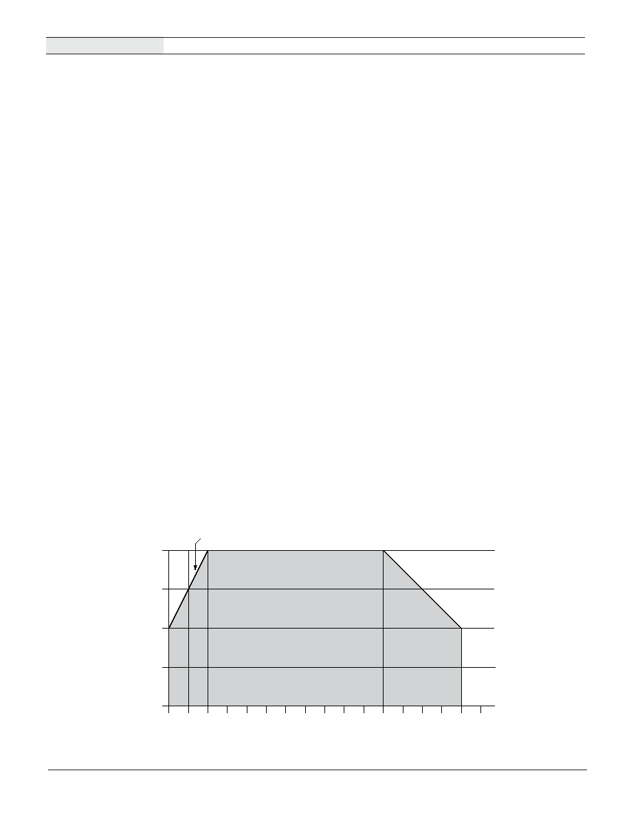
9. Temperature Derating (See Figure 3): All DMS-PS-CM supplies are
specifi ed to operate at their full rated power over the temp range of 0∞C
to +50∞C in still air (convection cooling) without any thermal derating.
For operation over +50∞C in still air, derate the output power linearly by
2.5% per ∞C down to 50% rated power at +70∞C. To operate the units at
full rated power between +50∞C and +70∞C, a minimum forced-airfl ow
of 100 LFM is required. For operation below 0∞C, derate the output
power linearly by 2.0% per ∞C down to 50% rated power at ≠25∞C.
Unless forced air with the velocity noted above is employed, DMS-
PS-CM supplies should never be mounted upside down (terminal
blocks facing down). Also, always provide suffi cient clearances in order
to ensure adequate airfl ow around the supply.
10. V1 Peak Capabilities: DMS-PS-CM power supplies have a maximum
continuous output-current rating that's specifi ed in the Ordering and
Selection Guide. In addition, each model's V1 output can intermittently
supply 120% of its continuous rated current for short periods of time if
the duty cycle is less than 10%. Peak current ratings do not apply to
the auxiliary outputs V2 or V3.
11. Isolated Outputs: Unlike the majority of competitive ac/dc power sup-
plies, all dual- and triple-output DMS-PS-CM power supplies feature
fully-isolated outputs. This is an important feature when, for reasons
of high common mode voltages, an instrument's input circuit must be
isolated from the system ground. All V1 outputs are isolated from the ac
mains by a minimum of 3000Vac, while auxiliary outputs V2 and V3 are
isolated from one another by 2000Vdc, and fromV1 by 1000Vdc. The
low noise, double-isolated auxiliaries are ideal for powering sensitive
instrumentation that requires low ac leakage-currents.
All ac/dc and dc/dc power components utilized in the construction
of DMS-PS-CM power supplies are 100% hi-pot tested during their
manufacturing processes. In addition, after fi nal assembly by DATEL,
all models are subjected to an additional hi-pot testing consisting of
1 0 0
7 5
5 0
2 5
0
≠25
≠10
0
10
15
20
25
30
35
40
45
50
55
60
65
70
70∫C
2.5% / ∫C
2.0% / ∫C
Output P
o
w
e
r (%)
75
Figure 3. Temperature Derating
H I G H E F F I C I E N C Y , A C / D C I N S T R U M E N T A T I O N P O W E R S U P P L I E S
DMS-PS-CM Series
5
DATEL, Inc., Mansfi eld, MA 02048 (USA)
∑
Tel: (508)339-3000, (800)233-2765 Fax: (508)339-6356
∑
E≠mail: sales@datel.com
∑
Internet: www.datel.com
3. Model Selection & Energy Conservation: In order to achieve the
lowest possible energy consumption, be sure to determine your appli-
cation's total current requirements. This is especially true when using
DMS-PS-CM supplies to power DATEL's energy-effi cient LED and/or
LCD display digital panel meters (DPMs) and process monitors. In
general, choose a power supply that will accommodate your maximum
current consumption plus a 20% margin. Choosing the lowest-wattage
model suitable for a given application will provide lower procurement
costs and lower long-term operating costs.
When calculating total current requirements in installations employing
three or more DMS-Series meters, it is acceptable practice to use each
meter's typical current consumption rating. However, be sure to consult
the relevant product datasheets for all instrumentation comprising your
application.
For applications where DMS-PS-CM power supplies will be powering
only DATEL DPM's, a 5-Watt DMS-PS3-CM can power up to four, stan-
dard intensity (`-RS' suffi x) red-LED DMS-30PC meters: two meters on
V1, and one meter each on V2 and V3. The same DMS-PS3-CM could
also be used to power over 40 low-power red DMS-30PC meters (`-RL'
suffi x), or over 800 DMS-30LCD non-backlit meters! Of course, these
statements are made without regard to ground-loop problems that may
be encountered when powering 800 DPM's from a single power supply.
1000Vac sequentially applied between the ac mains input and each
output, and between each output and all other outputs.
Application Information
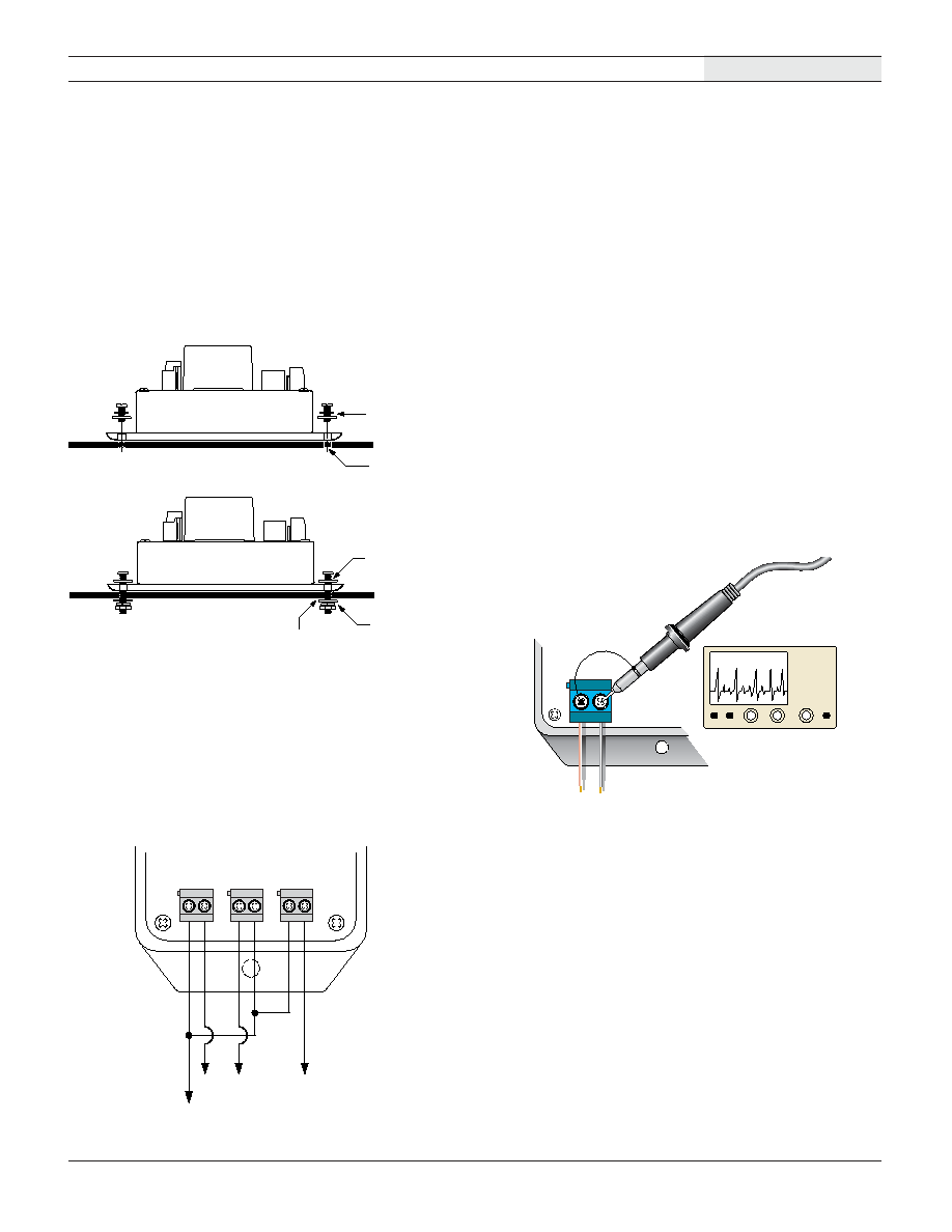
1. Chassis Mounting Considerations: In order to minimize self-heating,
DMS-PS-CM power supplies should always be mounted in either a
vertical or horizontal position. Avoid mounting units upside-down or in
close proximity to other heat-generating devices. Also, be sure to use
the mounting hardware described in Figure 4 below in order to ensure
a secure, vibration-resistant installation.
Figure 4. Chassis Mounting
2. Bipolar Operation (See Figure 5): DMS-PS-CM power supplies' fully
isolated outputs allow for the generation of bipolar (positive and nega-
tive) supply voltages. Bipolar outputs can be used to power dual-supply
operational amplifi ers, as well as any other type of instrumentation that
requires bipolar supply voltages. However, please keep in mind that
when connecting and operating any two outputs in this fashion, each
output retains its maximum current rating.
COM
+24V
≠5V
+5V
≠ +
≠ +
≠ +
V1 V2
DMS-PS6-CM
V3
Figure 5. Bipolar Connections
Figure 6. Measuring Ripple and Noise
Panel/Chassis
Threaded
Hole
Screw,
Split Lock Washer,
Flat Washer
Panel/Chassis
Hole
Flat Washer,
Split Lock Washer,
Nut
Screw,
Flat Washer
Oscilloscope
BW = 20MHz
DMS-PS-CM
V1
+
≠
Scope Probe
H I G H E F F I C I E N C Y , A C / D C I N S T R U M E N T A T I O N P O W E R S U P P L I E S
DMS-PS-CM Series
6
DATEL, Inc., Mansfi eld, MA 02048 (USA)
∑
Tel: (508)339-3000, (800)233-2765 Fax: (508)339-6356
∑
E≠mail: sales@datel.com
∑
Internet: www.datel.com
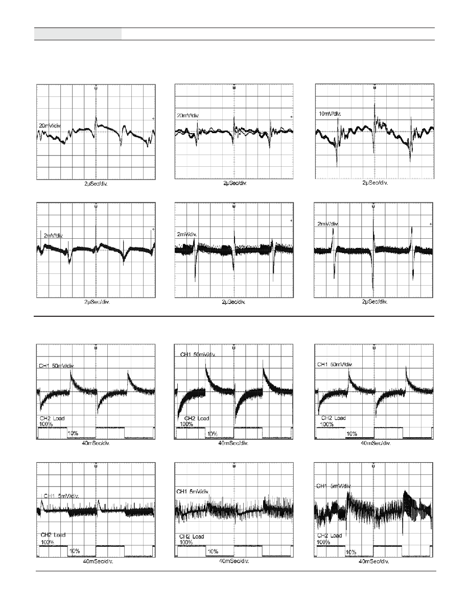
DMS-PS3-CM V1
(+5V)
Typical Performance Curves
T
A
= +25∞C, V
IN
= 120V @60Hz
Noise and Ripple - 100% Load, 20MHz Bandwidth
Transient Response - 10% to 100% Load Step
DMS-PS6-CM V1
(+24V)
DMS-PS9-CM V1
(+24V)
DMS-PS3-CM V2
(+4.85V)
DMS-PS6-CM V2
(+4.85V)
DMS-PS9-CM V2
(+4.85V)
DMS-PS3-CM V2
(+4.85V)
DMS-PS6-CM V2
(+4.85V)
DMS-PS9-CM V2
(+4.85V)
DMS-PS3-CM
V1 (+5V)
DMS-PS6-CM
V1 (+24V)
DMS-PS9-CM
V1 (+24V)
DATEL, Inc. 11 Cabot Boulevard, Mansfi eld, MA 02048-1151
Tel: (508) 339-3000 (800) 233-2765 Fax: (508) 339-6356
Internet: www.datel.com Email: sales@datel.com
DATEL (UK) LTD. Tadley, England Tel: (01256)-880444
DATEL S.A.R.L. Montigny Le Bretonneux, France Tel: 01-34-60-01-01
DATEL GmbH M¸nchen, Germany Tel: 89-544334-0
DATEL KK Tokyo, Japan Tel: 3-3779-1031, Osaka Tel: 6-6354-2025
DATEL makes no representation that the use of its products in the circuits described herein, or the use of other technical information contained herein, will not infringe upon existing or future patent rights. The descriptions contained herein do
not imply the granting of licenses to make, use, or sell equipment constructed in accordance therewith. Specifi cations are subject to change without notice. The DATEL logo is a registered DATEL, Inc. trademark.
DMS-PS-CM Series
Æ
Æ
H I G H E F F I C I E N C Y , A C / D C I N S T R U M E N T A T I O N P O W E R S U P P L I E S
DS-0505A
01/02
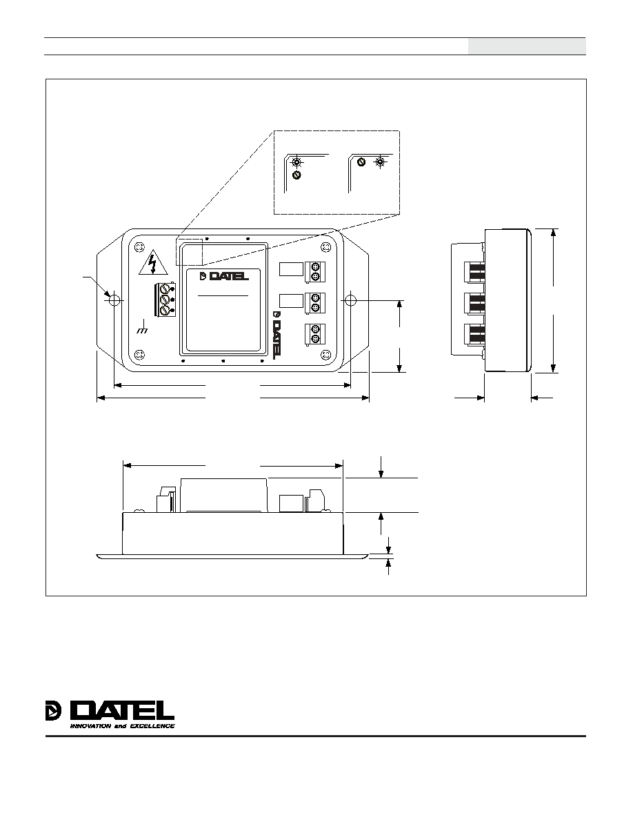
0.188
(4.8)
0.125
(3.2)
5W models: 0.77 (19.6)
10W models: 0.87 (22.1)
16W models: 0.93 (23.6)
4.625 (117.5)
1.000 (25.4)
5.125 (130.2)
TB4
TB1
TB2
TB3
AC(L)
AC(N)
FG
+
V1
≠
+
V2
≠
+
V3
≠
Æ
Æ
Æ
Æ
DMS-PSX-CM
AC/DC POWER SUPPLY
2.835
(72.0)
1.42
(36.1)
4.165 (105.8)
Power On
See detail
5 Watt &
10 Watt Models
16 Watt Models
V1 Adjust
Power
On
V1
Adjust
Detail
Mechanical Specifi cations
MECHANICAL DIMENSIONS: Inches (mm)
TOLERANCES: 2 PL DEC ±0.02 (±0.51)
3 PL DEC ±0.010 (±0.254)
ISO 9001 Registered