 | –≠–ª–µ–∫—Ç—Ä–æ–Ω–Ω—ã–π –∫–æ–º–ø–æ–Ω–µ–Ω—Ç: FLT-100 | –°–∫–∞—á–∞—Ç—å:  PDF PDF  ZIP ZIP |

100Vdc, 10 Amp and 20 Amp
Differential/Common-Mode Filters
Filter Modules
FLT Models
Features
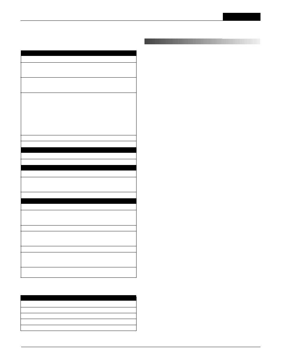
Figure 1. Simplifi ed Schematics
INNOVATION and EX C ELL E N C E
Æ
Æ
Compatible with most modern switching
DC/DC converters
Provides both common-mode and
differential-mode fi ltering
Facilitates compliance with all conducted-
emissions specifi cations
Small size; PCB mountable
≠40 to +100∞C (case) operation
UL94V-0 rated package material
UL approved
Lucent FLTR100V10/20 compatible
DATEL, Inc., Mansfi eld, MA 02048 (USA) ∑ Tel: (508)339-3000, (800)233-2765 Fax: (508)339-6356 ∑ Email: sales@datel.com ∑ Internet: www.datel.com
Although agency-imposed conducted-emissions standards are targeted for sys-
tem-level designs, designers often apply these standards at the component level
to ensure system-level compliance. For those DC/DC converters that do not meet
these standards, DATEL offers the FLT-100V Series EMI fi lters. When used with the
recommended external capacitors, this family of fi lters signifi cantly reduces both the
common-mode and differential emissions injected back to the power source.
These rugged fi lters are packaged in non-conductive, UL94V-0 rated, 1" x 2" x
0.5" (FLT-100V10) and 1.6" x 2" x 0.5" (FLT-100V20) packages. Components and the
pcb are coated with a humidity-sealing conformal coating and then encapsulated with
a thermally conductive potting compound providing outstanding moisture/vibration
resistance. Both fi lters are rated for 100Vdc differential input voltage and are internally
bypassed with a telecom/datacom preferred mylar, self-healing, 100Vdc rated capaci-
tor. Input-to-GND and Output-to-GND isolation voltages are guaranteed at 1500Vdc.
Inductor copper losses and pcb trace losses are minimized to attain a low Input-to-
Output per leg resistance of 9.5m
for FLT-100V10 and 4.8m for FLT-100V20 when
measured at +25∞C. Both Filters are fully characterized to 20MHz for both common-
mode and differential-mode dynamic insertion losses. The FLT-100V series EMI fi lters
are UL approved.
GROUND
GROUND
+INPUT
+INPUT
+INPUT
≠INPUT
≠INPUT
≠INPUT
+OUTPUT
+OUTPUT
+OUTPUT
≠OUTPUT
≠OUTPUT
≠OUTPUT
Model FLT-100V10
Model FLT-100V20
PRELIMINARY
F I L T E R M O D U L E S
FLT Series
Performance Specifi cations and Ordering Guide
P A R T N U M B E R S T R U C T U R E
100V10 = 100 Volt input
10 Amp rating
100V20 = 100 Volt input
20 Amp rating
100V10
FLT
-
Filter Module
Series
FLT-100V10 100 10 4.8 ≠37 ≠58 F1, P45
FLT-100V20 100 20 9.5 ≠29 ≠48 F2, P46
Specifi cations at T
A
= +25∞C unless otherwise noted.
50 load @ 500kHz.
Resistance
Common-Mode
Differential-Mode
V
IN
Average current
Per Leg
Insertion Loss
Insertion Loss
Package
Model
(Volts,
max.)
(Amps
max.)
Typ.
(m
, max.)
(dB, typ.)
(dB Typ.)
(Case, Pinout)
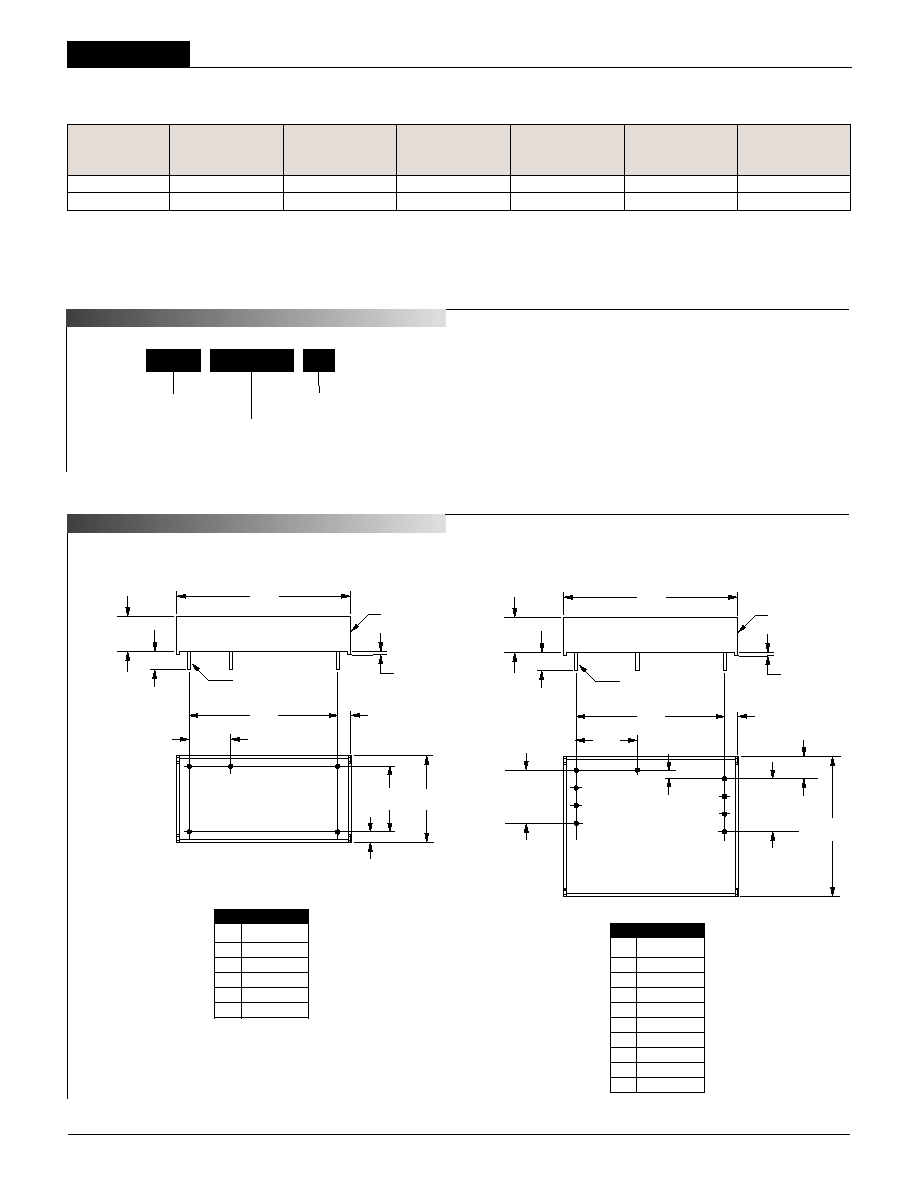
M E C
A N I C A L S P E C I F I C A T I N S
2
I/O
Connections
Pin Function
P45
1 +Input
2
≠Input
3
Ground
4
≠Output
5
+Output
0.15
(3.81)
0.475
(12.07)
0.13
(3.30)
1.700
(43.18)
0.750
(19.05)
BOTTOM VIEW
1.00
(25.40)
PLASTIC CASE
STANDOFF
0.020 (0.51)
2.00
(50.80)
0.20 MIN
(5.08)
0.48
(12.19)
0.031 ±0.001 DIA.
(0.787 ±0.025)
4
5
3
1
2
0.15
(3.81)
0.10
(2.54)
0.700
(17.78)
0.25
(6.35)
1.700
(43.18)
0.600
(15.24)
3 EQ. SP. @
0.200 (5.08)
BOTTOM VIEW
1.60
(40.64)
0.600
(15.24)
3 EQ. SP. @
0.200 (5.08)
PLASTIC CASE
STANDOFF
0.020 (0.51)
2.00
(50.80)
0.20 MIN
(5.08)
0.48
(12.19)
0.040 ±0.001 DIA.
(10.16 ±0.025)
3
2
1
4
9
5
6
7
8
Case F2
I/O
Connections
Pin Function
P46
1 +Input
2
+Input
3
≠Input
4
≠Input
5
≠Output
6
≠Output
7
+Output
8
+Output
9
Ground
Case F1
Model FLT-100V10
Model FLT-100V20
L1
-
Add suffi x as desired
Part Number Suffi xes
The FLT-100V series offer shorter pins than those shown in the
mechanical specifi cations drawing.
L1 Suffi x Short pins: 0.110" (+0.015/≠0.010)
L2 Suffi x Short pins: 0.145" (+0.015/≠0.010)
FLT Models
F I L T E R M O D U L E S
Performance/Functional Specifi cations
Typical @ T
A
= +25∞C under nominal line voltage, balanced "full-load" conditions, unless noted.
Input
Input Voltage Range: 100 Volts maximum
Average Current @ +25∞C:
FLT-100V10 10 Amps maximum
FLT-100V20 20 Amps maximum
Average Current @ +60∞C:
FLT-100V10 10 Amps maximum
FLT-100V20 20 Amps maximum
Resistance Per Leg:
FLT-100V10:
@ 25∞C 9.5m
@ ≠40∞C 7.6m
@ +125∞C 11.8m
FLT-100V20:
@ 25∞C 4.8m
@ ≠40∞C 4m
@ +125∞C 6.3m
Isolation Voltage Input to GND 1500Vdc minimum
Isolation Voltage Output to GND 1500Vdc minimum
Dynamic Characteristics
Differential-Mode Insertion Loss See Ordering Guide
Common-Mode Insertion Loss See Ordering Guide
Environmental
Operating Case Temperature ≠40 to +100∞C
MTBF @ 100∞C Case
FLT-100V10 2,856,374 hours
FLT-100V20 2,521,681 hours
Storage Temperature ≠55 to +125∞C
Physical
Case Material Plastic, UL 94V-0 rating
Case Dimensions:
FLT-100V10 1" x 2" x 0.5" (25.4 x 50.8 x 12.7mm)
FLT-100V20 1.6" x 2" x 0.5" (40.6 x 50.8 x 12.7mm)
Pin Material Brass, solder coated
Pin Diameter:
FLT-100V10 0.031" (0.787mm)
FLT-100v20 0.040" (1.016mm)
Pin Length See Part Number Structure
Weight:
FLT-100V10 1.28 ounces (36.3 grams)
FLT-100V20 2.16 ounces (61.2 grams)
Lead Temperature
Soldering, 10 seconds +300∞C
+25∞C, 20lfm (natural convection).
+60∞C, 20lfm air fl ow (natural convection).
3
Absolute Maximum Ratings
Input Voltage Range 100 Volts
Isolation Voltage Input to GND 1500Vdc minimum
Isolation Voltage Output to GND 1500Vdc minimum
Operating Case Temperature ≠40 to +100∞C
Storage Temperature ≠55 to +125∞C
Description
The FLT-100V series of passive fi lters are optimized to reduce both common-
mode and differential-mode noise on both input and output lines of switching
DC/DC converters. The FLT-100V10 is rated for 10A of continuous current
while the FLT-100V20 is rated for 20A.
Differential-mode and Common-mode Noise
Designers who are faced with reducing conducted emissions in DC/DC
applications must address both differential-mode and common-mode noise.
Differences measured between the two input lines of the DC/DC converter
are classifi ed as differential noise. The dominant contribution to differential
noise is the switching action of the DC/DC converter. Consequently, the
majority of noise will be seen at the converter's switching frequency and it's
harmonics. The FLT-100V series fi lter uses a mylar, self healing, 100Vdc
rated input capacitor connected between the two input lines (traditionally
referred to as "X" capacitors), in conjunction with the leakage inductance of
the common mode chokes to attenuate the low-frequency differential noise.
In addition to the fi lter, a low-ESR input capacitor (C1 of Figure 2) is also
recommended at the input to the DC/DC to provide a low source impedance
and additional noise attenuation.
See typical performance curves for differential-mode insertion loss perfor-
mance.
Common-mode noise is measured as variations between the input lines (in
common) with respect to the Ground pin. Common-mode noise is generally
in the high frequency spectrum (>10MHz) and originates in the switching
components of the DC/DC converter. Internal capacitors from each line to
the ground pin (referred to as "Y" capacitors), connected between the two
common mode chokes, provides attenuation of this unwanted common-
mode noise. This ground pin should be connected to a relatively quiet
chassis ground point independent from the DC/DC converter case con-
nection. Note that a noisy chassis ground can inadvertently
introduce common-mode noise into the system. Some DATEL
DC/DC converters are designed with an internal input-to-outptut capacitor
to reduce common-mode noise generated from within the converter. In
addition, common-mode noise can be reduced with the addition of external
ceramic capacitors of 0.1uF to 1.0uF (C2 thru C6 of Figure 2) installed from
inputs and outputs to a shield plane connected to the DC/DC case; safety
standards may limit the size of these capacitors for some applications. See
typical performance curves for common-mode insertion loss performance.
T E C H N I C A L N O T E S
F I L T E R M O D U L E S
FLT Series
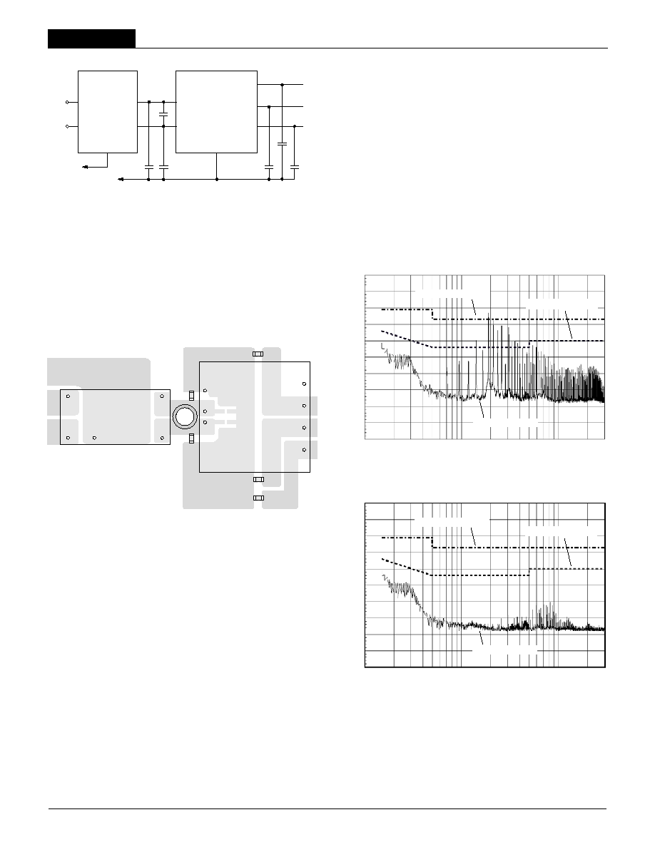
Conducted Emissions Performance
Conducted Emissions standards imposed by governing agencies must be
met at the system-level, not the component level. Many designers, however,
apply these standards to the individual components to assure system-level
compliance. The following performance graphs show the Conducted Emis-
sions improvements seen when using an FLT-100V series fi lter in series with
the input lines of a typical switching DC/DC converter. Conducted Emissions
testing was performed within a EMCO 5305 GTEM test cell utilizing EMCO
automated EMC test software. Signal levels were measured from an EMCO
3825/2 Line Impedance Stabilization Network (LISN) using a Hewlett Packard
8568B spectrum analyzer with an attached Hewlett Packard 85650A quasi-
peak adapter in peak detection. Limits are based on FCC Part 15 Subpart J
Class A and B, as well as EN 55022 Class A and B.
≠INPUT
+INPUT
GND
FLT-100V
FILTER
DC/DC
CONVERTER
C2
C1
C3
C4
C
SHIELD PLANE
CHASSIS
GND
CASE
OUTPUT
OUTPUT
≠INPUT
+INPUT
+V2
OUT
+V1
OUT
OUTPUT
RETURN
C6
4
5
3
1
2
4
5
3
1
2
C1
1
3
2
4
FLT-100V10
FILTER
TOP VIEW
DC/DC
CONVERTER
5
4
8
7
6
5
2
1
C4
C6
C5
C3
C2
Figure 2 shows a typical connection diagram for the attenuation of both
differential and common-mode noise when used as an input fi lter to a DC/DC
converter, while Figure 3 shows the recommended layout. Noise introduced
into circuits is dependent upon the characteristics of the load, layout and
grounding techniques, and cabling. Since application requirements differ, the
fi nal circuit confi gurations may be best obtained through empirical testing.
Figure 2. Typical Application Using FLT-100V Series Filters
in Front of a DC/DC Converter
Figure 3. Typical Layout Using FLT-100V Series Filters
in Front of a DATEL BWR-5/6-3.3/7-D12 Dual-Output DC/DC Converter
BWR-5/6-3.3/7-D12 Conducted Emissions
0.1
1.0
10.0
Conducted Emissions
EN 55022 Class A Limit
EN 55022 Class B Limit
100
90
80
70
60
50
40
30
20
10
0
Radiated Emissions (dBµV/M)
Frequency (MHz)
BWR-5/6-3.3/7-D12 Conducted Emissions
Using FLT-100V10 Filter
0.1
1.0
10.0
Conducted Emissions
EN 55022 Class A Limit
EN 55022 Class B Limit
100
90
80
70
60
50
40
30
20
10
0
Radiated Emissions (dBµV/M)
Frequency (MHz)
FLT Models
F I L T E R M O D U L E S
BWR-5/700-D48A
≠INPUT
+INPUT
+5V OUT
≠5V OUT
COMMON
10µF
≠5V
LOAD
10µF
+5V
LOAD
≠INPUT
+INPUT
GND
FLT-100V10
OUTPUT
OUTPUT
UWR-5/1800-D48A
≠INPUT
+INPUT
+5V OUT
COMMON
OUTPUT
OUTPUT
6.8µF
+5V
LOAD
≠INPUT
+INPUT
GND
FLT-100V10
Operating Temperature
Both the FLT-100V10 and FLT-100V20 are guaranteed for operation up to
+100∞C case temperature. Performance graphs (see typical performance
curves) are provided for both models that depict the case temperature rise
versus average current for various air fl ow conditions.
On/Off Control and External Fusing
To eliminate any current-path bypassing of the fi lter, the on/off control circuitry
used to control the DC/DC converter should be referenced to the ≠Input pin of
the converter and not to the ≠Input of the Filter.
The FLT-100V series fi lters do not provide internal fusing, therefore An
external fuse of appropriate DC/DC rating should be provided externally.
Using a Single Filter with Multiple Converters
A single FLT-100V series fi lter can be used with multiple DC/DC converters
provided that the maximum rated current is observed. The use of common-
mode chokes in the design of these fi lters, however, requires that the +Input
current and ≠Input current be equal. A small imbalance in these currents may
cause the inductor to saturate and degrade the fi lter's performance.
Input Capacitor
FLT-100V series fi lters incorporate an internal, multi-layer fi lm polymer capac-
itor between the input lines for differential-mode noise fi ltering. This telecom/
datacom preferred capacitor provides electrical stability under both AC and
DC current loads. The capacitors insulation resistance tends to improve
under the stresses of heat and voltage. A typical ESR of 6 milli-OHMs
@ 500kHz, provides the necessary low impedance for high frequency input
current handling.
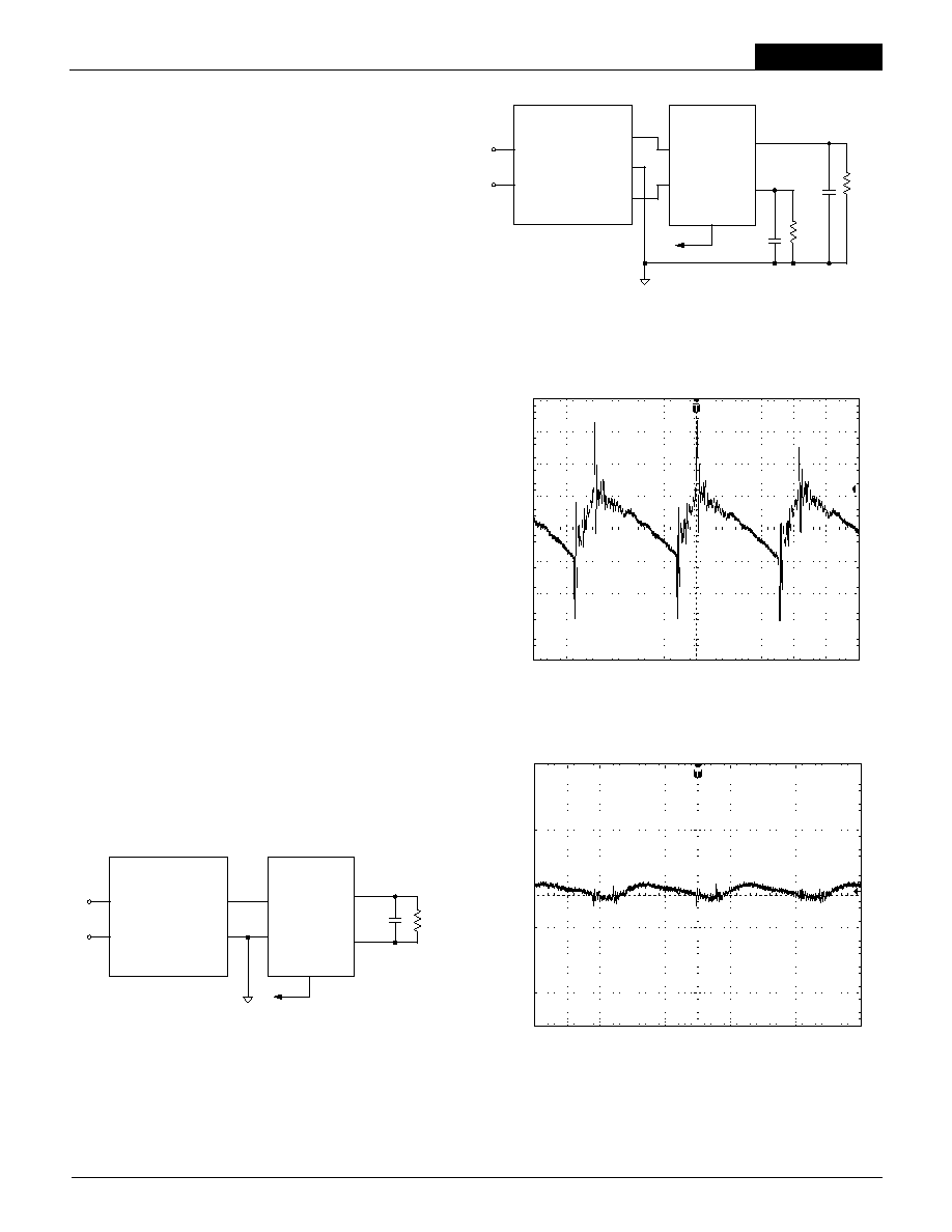
Using FLT-100V as an Output Filter
Although optimized for use an input conducted emissions fi lter, the FLT-100V
series can be used as an output fi lter for DC/DC converters to reduce output
ripple and attenuate high frequency noise. Figures 4 and 5 show the recom-
mended connections for both unipolar and bipolar applications. Depending
upon application and desired performance, the Gnd pin connection can be
made at the output return, case shield plane, or left fl oating.
Output ripple and noise improvements are shown in the following illustrations
for a typical DC/DC converter that is using the setup shown in Figure 5.
Output Ripple and Noise of BWR-5/700-D48A
(Using single leg of FLT-100V10 and 10µF capacitance.)
20mV/div, 20MHz Bandwidth
Output Ripple and Noise of BWR-5/700-D48A
(No external capacitance.)
20mV/div, 20MHz Bandwidth
Figure 5. Using FLT-100V10 as an Output Filter for Bipolar DC/DC
Figure 4. Using FLT-100V10 as an Output Filter for Unipolar DC/DC
F I L T E R M O D U L E S
FLT Series
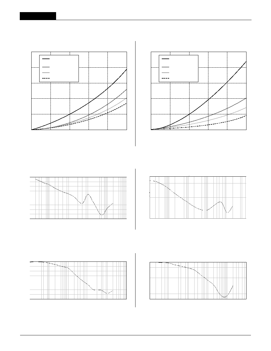
FLT-100V10 Common-Mode Insertion Loss
(
Into 50 Ohm Load)
Common-Mode Inser
tion Loss (dB)
Frequency (MHz)
0.001
0.010
0.100
1.000
10.000
100.000
0
≠10
≠20
≠30
≠40
≠50
≠60
≠70
≠80
Diff
erential-Mode Inser
tion Loss (dB)
Frequency (MHz)
FLT-100V10 Differential-Mode Insertion Loss
(
Into 50 Ohm Load)
0
≠10
≠20
≠30
≠40
≠50
≠60
≠70
≠80
≠90
0.001
0.010
0.100
1.000
10.000
100.000
Common-Mode Inser
tion Loss (dB)
Frequency (MHz)
FLT-100V20 Common-Mode Insertion Loss
(
Into 50 Ohm Load)
0
≠10
≠20
≠30
≠40
≠50
≠60
≠70
0.001
0.010
0.100
1.000
10.000
100.000
Diff
erential-Mode Inser
tion Loss (dB)
Frequency (MHz)
FLT-100V20 Differential-Mode Insertion Loss
(
Into 50 Ohm Load)
0
≠10
≠20
≠30
≠40
≠50
≠60
0.001
0.010
0.100
1.000
10.000
100.000
0
2
4
6
8
10
50
40
30
20
10
0
Current Through Each Leg (Amps)
Case
T
emperature Rise Abo
ve Ambient (∞C)
0.1m/s (20lfm)
Natural Convection
1.0m/s (197lfm)
2.0m/s (394lfm)
3.0m/s (591lfm)
0
4
8
12
16
20
50
40
30
20
10
0
Current Through Each Leg (Amps)
Case
T
emperature Rise Abo
ve Ambient (∞C)
0.1m/s (20lfm)
Natural Convection
1.0m/s (197lfm)
2.0m/s (394lfm)
3.0m/s (591lfm)
Case Temperature Rise vs. Average Current and Air Flow
Typical Differential-Mode Insertion Loss Curves
Typical Common-Mode Insertion Loss Curves
FLT-100V10
FLT-100V20

FLT Models
F I L T E R M O D U L E S
7
DATEL makes no representation that the use of its products in the circuits described herein, or the use of other technical information contained herein, will not infringe upon existing or future patent rights. The descriptions contained herein do
not imply the granting of licenses to make, use, or sell equipment constructed in accordance therewith. Specifi cations are subject to change without notice. The DATEL logo is a registered DATEL, Inc. trademark.
DATEL (UK) LTD. Tadley, England Tel: (01256)-880444
DATEL S.A.R.L. Montigny Le Bretonneux, France Tel: 01-34-60-01-01
DATEL GmbH M¸nchen, Germany Tel: 89-544334-0
DATEL KK Tokyo, Japan Tel: 3-3779-1031, Osaka Tel: 6-6354-2025
DATEL, Inc. 11 Cabot Boulevard, Mansfi eld, MA 02048-1151
Tel: (508) 339-3000 (800) 233-2765 Fax: (508) 339-6356
Internet: www.datel.com Email: sales@datel.com
ISO 9001 REGISTERED
INNOVATION and EX C ELL E N C E
Æ
Æ
DS-0489 12/01