 | –≠–ª–µ–∫—Ç—Ä–æ–Ω–Ω—ã–π –∫–æ–º–ø–æ–Ω–µ–Ω—Ç: PC-414LVS | –°–∫–∞—á–∞—Ç—å:  PDF PDF  ZIP ZIP |
Æ
Æ
FEATURES
∑∑
∑∑
∑
Up to 10 MHz A/D sample rate
∑∑
∑∑
∑
Very low harmonic distortion
∑∑
∑∑
∑
Analog input comparator trigger
∑∑
∑∑
∑
Choice of 12, 14, or 16-bit A/D resolution
∑∑
∑∑
∑
Optional 2 to 8-channel simultaneous sampling
∑∑
∑∑
∑
On-board FIFO memory up to 16,384 samples
∑∑
∑∑
∑
Ideal for FFT's, DSP, or array processor "front ends"
∑∑
∑∑
∑
Non-bus burst parallel port for seamless recording
Offering very high system speed, the PC-414 is a multi-channel
analog input board for ISA compatible computers. Input
bandwidth is available up to 5 MHz and may be sampled at up
to 10 MHz. A common motherboard is used, with the analog
section contained in a pluggable 2" by 4" module. This allows
for a family of several different Sample/Hold - A/D Converter
speed and resolution options by exchanging analog modules.
The analog input ranges of the A/D converter are selectable
as unipolar 0 to +10 V, or bipolar ±5 V, or ±10 V depending on
the model. Model PC-414E offers 16 single-ended or 8
differential high speed channels.
Models PC-414F, G, J, K, L, M, and P include a simultaneous
sampling section. This function acquires signals on parallel
channels at the same time. This prevents phase errors and
skewing of multichannel correlated signals. Applications
include high speed cross-channel computation, beam-former
coherency for sonar or acoustics, telemetry, multiple carrier
demodulation, and highly concurrent system testing.
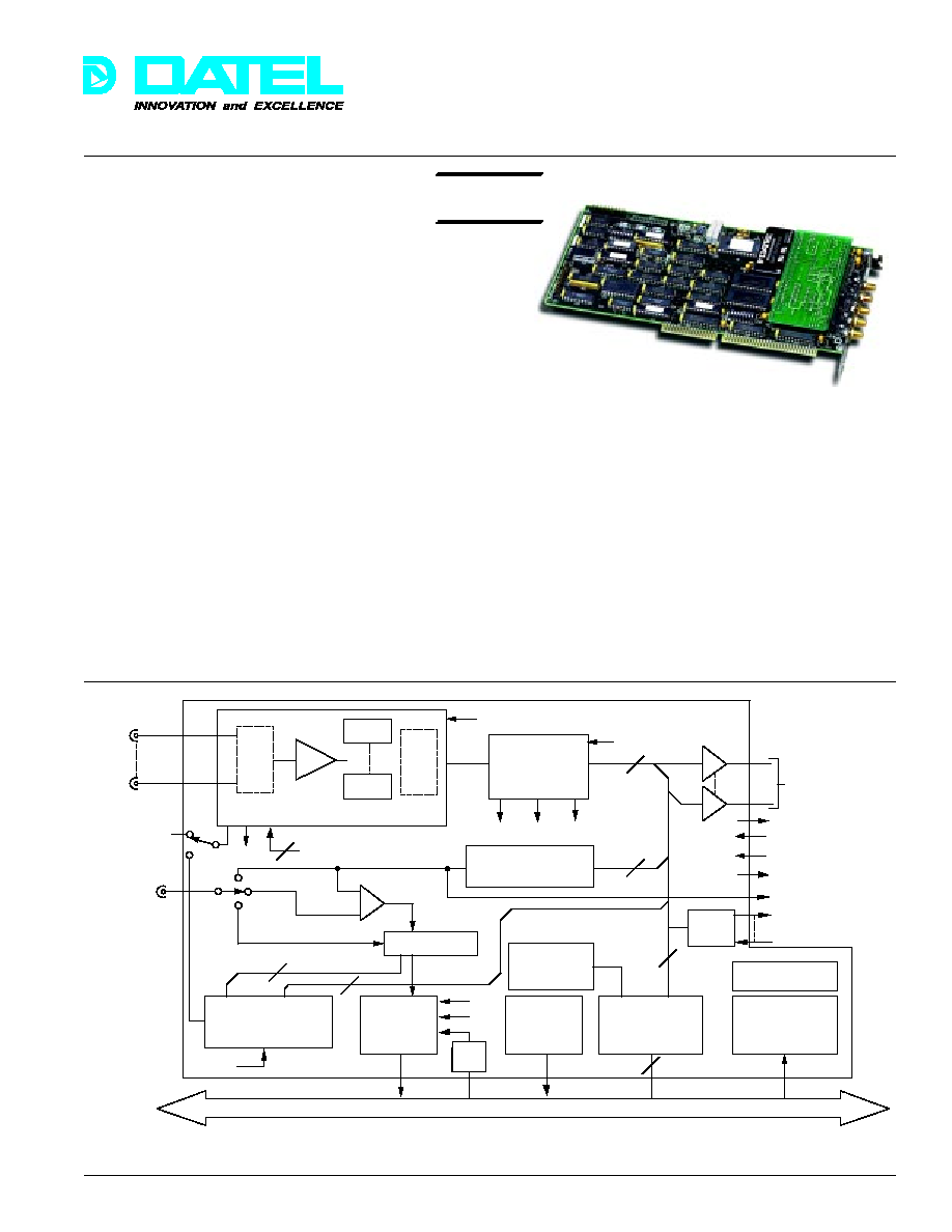
Figure 1. Functional Block Diagram
A/D data passes to an on-board First-In, First-Out (FIFO) data
memory and then to the host computer bus interface under
software control. The FIFO acts to uncouple the precise
timing of the A/D section from the block-oriented data
transfers on the bus. The design can continuously collect
analog data with non-stop converter triggering while data is
simultaneously read from the FIFO. This allows the collection
of "seamless" wide-bandwidth signals of millions of samples or
greater. Functions such as FFT sampling cannot tolerate lost
samples without increases in "arithmetic" noise during
computation processing.
Data can be transferred to mass storage peripherals such as
disk or magnetic tape. Applications include long-baseline
studies in astrophysics, component life testing, and
anomalous pattern search.
Channel Address Sequencer
FIFO
Memory
Empty Half
Full
Trigger Control
Trigger In
D/A Out
External
Trigger
Trigger
Comparator
Analog Trigger
D/A Converter
82C54 Programmable
Interval Timer
Interrupt
Request
DMA
Request
I/O Bus
Interface
DC/DC
Power Converter
Base Address
Select
Registers
8MHz
ISA BUS
Half
Full
DMA
T/C
Parallel Outport or
DSP COMM Port
D/A Output
Ready Output
Acknowledge Input
External Enable Input
+5V
SSH Control
ACQ
EOC
Reset
FIFO Flags
A/D Start Clock
M
U
X
A/D
A/D
C
T
L
Analog
Inputs
Digital
I/O
8 out,
8 in
Pluggable Analog Section
PC-414
High-Speed Analog Input Board
for ISA Computers
Now with
LabVIEW
Æ
VI's
NEW
DATEL, Inc., Mansfield, MA 02048 (USA)
∑
Tel: (508)339-3000, (800)233-2765 Fax: (508)339-6356
∑
Email: sales@datel.com
∑
Internet: www.datel.com
79
PC-414
Æ
Æ
DATEL, Inc., Mansfield, MA 02048 (USA)
∑
Tel: (508)339-3000, (800)233-2765 Fax: (508)339-6356
∑
Email: sales@datel.com
∑
Internet: www.datel.com
The FIFO data output may also be routed under host software
control to an on-board parallel data port instead of being sent to
the computer bus. This parallel burst channel data may be read
by an external processor at very high speeds and avoids
possible speed restrictions of the computer bus. The outport
uses a very simple ready/acknowledge transfer handshake which
is adaptable to any remote parallel port including DT Connect
Æ
.
See model PC-414COM using a DSP COMM port interface.
The analog section of the PC-414 is optimized for high signal
quality and very low dynamic noise. The PC-414 is ideal as
an FFT "front-end" or DSP quantizer for array processors.
The A/D conversion timing section is designed for accurate multi-
scan data acquisition. Software programmable timers control the
interval between each conversion and each multichannel scan.
A programmable sample counter allows sample blocks of
specified length independent of FIFO length. The timer/counter
section uses a precision on-board crystal clock. Timeout and
sample count activities may be monitored using I/O status
registers and/or programmable interrupts. The interrupt method
may be fully synchronized with software programmable DMA
transfers directly to host computer memory.
S/H - A/D triggering can originate from several sources under
software control. The internal timebase is the normal trigger
source although single conversions or scans may be directly
commanded by host I/O register writes. An external trigger
clock may also be used to precisely synchronize sampling with
external events. This external trigger may start a single
multichannel scan or "N" multiple scans separated by
programmable delays.
Analog sampling can also be level-triggered using an on-board
analog comparator and an external level input. The reference
trigger level to the comparator is derived from an on-board 12-
bit D/A converter. If preferred, the D/A converter may also be
used as a general purpose analog output channel.
The PC-414B, D, F, G, H, K, M, N, and P versions contain five
SMA coaxial signal connectors. Four connectors are for the
sampled analog channels. The fifth connector is used for
external timebase clock input, external analog trigger signal,
or for the analog output. The PC-414E, J, and L versions
contain 25-pin "D" connectors (DB-25S). The burst channel
parallel port uses an internal dual row header.
The computer interface conforms to the PC-AT bus structure.
All data transfers (control, status, and A/D data) use 16-bit
transfers. Interrupt level selection is done via software.
Interrupt servicing is generated for a variety of reasons such
as A/D data read, DMA terminal count, sample count
reached, FIFO half-full, or FIFO full.
A/D output data coding is right-justified two's complement with
sign extension, if desired, straight binary coding can also be
selected making it directly compatible with high level computer
languages such as "C", Visual C++, Borland C Builder, Visual
Basic, and others.
Software
The PC-414 can be controlled via optional DOS or Windows
NT or 95/98 Control panels, third party software such as
LabVIEW, or user written code in languages such as Visual
C++, Borland C Builder, Visual Basic, etc.
PC-414SET
An MS-DOS based menu driven acquisition
program. Includes setup and configuration
functions, data acquisition via interrupt and DMA,
D/A and counter timer control. Software also
includes A/D and D/A calibration procedures.
∑ Automatically configures to the display
adapter, CPU, and mouse
∑ Sets the I/O base address
∑ Initializes the interrupt and DMA systems
and D/A output
∑ Allocates base or extended memory
∑ Performs self-test and A/D-D/A calibration
∑ Configures A/D sample rate, frame rate,
and sample counter
∑ Selects trigger mode and DMA or I/O block
transfer
∑ Selects disk file output format to integer
binary, float binary, or ASCII float
∑ Saves data to base memory, extended
memory, or disk
∑ Full source code in "C" and assembly is
available
∑ MS-DOS or WINDOWS version (visual
"C" interface)
PC-414SRC
Source code for PC-414SET, written in C.
PC-414WIN
A Windows 95/98 or NT GUI control panel
PC-414NT
incorporates all the functions of the PC-414.
Functions include configuration and setup,
analog input to file or disk, analog output, analog
and digital triggering, digital I/O, and calibration.
PC-414WINS
Source code for PC-414WIN written in
Borland C Builder.
PC-414LV
Bridge driver software to LabVIEW 4.0 and 3.1.
PC-414LVS
Source code for PC-414LV allows users to
reduce high level VI's to lower level VI's.
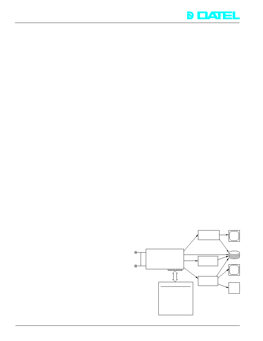
Figure 2. PC-414SET Software Operation
Analog
Inputs
PC-414SET
∑ Window-driven user interface
∑ Configure hardware
∑ Start acquisition
∑ Send data over parallel port
∑ Store data to memory and /or
disk file
∑ View data
∑ Access digital I/O port
∑ A/D and D/A calibration
∑ Update D/A
PC-414
Remote receiver
e.g. DSP board,
memory board, etc.
Host
Memory
User written
program
D/A
Converter
Graphics
Display
Disk
Display
Parallel
Port
Start &
Exit Mode
80
PC-414
Æ
Æ
DATEL, Inc., Mansfield, MA 02048 (USA)
∑
Tel: (508)339-3000, (800)233-2765 Fax: (508)339-6356
∑
Email: sales@datel.com
∑
Internet: www.datel.com
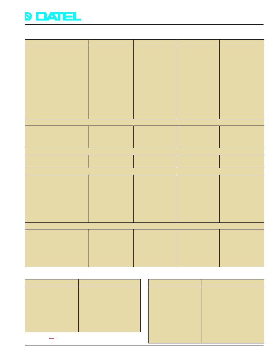
FUNCTIONAL SPECIFICATIONS
(Typical at +25 ∞C, dynamic conditions, gain = 1, unless noted)
PC-414F
2 Simultaneous
(two A/D's)
Single Ended
0 to +10 V
±5 V
±15 V
2 µs
--
1 k
165 ns
20 ns
±40 ps
12 bits
400 ns
±1
±1
±0.1
±0.1
2 MHz
2 MHz/chan.
(2 chans.)
≠70 dB
PC-414E
16SE/8D [Note 8]
(single A/D)
SE or Diff.
0 to +10 V
±10 V
±5 V
±15 V
2 µs
±10 V
100 M
750 ns
20 ns
±40 ps
12 bits
500 ns
±1
±0.75
±0.1
±0.1
2 MHz
500 kHz
[Note 4]
≠72 dB
PC-414B
4
(single A/D)
Single Ended
0 to +10 V
±10 V
±5 V
±15 V
2 µs
--
10 M
750 ns
20 ns
±100 ps
14 bits
1.6 µs
±1.5
±1
±0.3
±0.3
500 kHz
330 kHz
≠75 dB
ANALOG INPUTS
Number of Channels
Input Configuration
(non-isolated) [Note 19]
Full Scale Input Ranges
(user-selectable) (gain = 1)
[Notes 1 & 16]
Input Overvoltage
(no damage, power on)
Overvoltage Recovery
Time, maximum
Common Mode Voltage
Range, maximum
Input Impedance [Notes 6 &10]
Acquisition Time
(FSR step to 0.01% of FSR, max.)
Aperture Delay
Aperture Delay Uncertainty
Resolution
Conversion Period
Integral Non-linearity
(LSB of FSR)
Differential Non-linearity
(LSB of FSR)
Full Scale Temperature
Coefficient (LSB per ∞C)
Zero or Offset
Temperature Coefficient
(LSB per ∞C)
Throughput to FIFO
(single channel, gain = 1)
Throughput to FIFO
(sequential channels,
gain = 1)
Total Harmonic Distortion
[Note 3]
PC-414D
1
(single A/D)
Differential
±5 V
±15 V
2 µs
±1 V
2 k
50 ns
10 ns
±7 ps
12 bits
200 ns
±2
±1
±0.1
±0.3
5 MHz [Note 9]
--
≠68 dB
SAMPLE/HOLD
A/D CONVERTER
SYSTEM DC CHARACTERISTICS [Note 7]
SYSTEM DYNAMIC PERFORMANCE [Note 2]
ANALOG INPUTS
Programmable Gains
See Note 1
Common Mode Rejection
(DC - 60 Hz)
-80 dB (g = 100) (414E)
Addressing Modes
1. Single channel
2. Simultaneous sampling
3. Sequential with
autosequenced addressing
4. Random addressing by host
software
A/D CONVERTER
Output Coding
Positive-true, right justified,
straight bin. (unipolar) or right-
justified 2's complement
(bipolar) with sign extension
thru bit 15
Trigger Sources
1. Local Pacer frame clock
(Software selectable)
2. External TTL frame clock
3. Analog threshold comp.
A/D Sample Clock
1. Internal programmable
(software selectable)
82C54 timer
2. Ext. TTL input, active low
Please read all notes carefully.
The PC-414J in short-cycled addressing is recommended in place of the PC-414A. Model PC-414E can substitute for the PC-414C.
81
PC-414
Æ
Æ
DATEL, Inc., Mansfield, MA 02048 (USA)
∑
Tel: (508)339-3000, (800)233-2765 Fax: (508)339-6356
∑
Email: sales@datel.com
∑
Internet: www.datel.com
ANALOG INPUTS
Number of Channels
Input Configuration
(non-isolated) [Note 19]
Full Scale Input Ranges
(user-selectable) (gain = 1)
[Notes 1 & 16]
Input Overvoltage
(no damage, power on)
Overvoltage Recovery
Time, maximum
Common Mode Voltage
Range, maximum
Input Impedance [Notes 6 &10]
Acquisition Time
(FSR step to 0.01% of FSR, max.)
Aperture Delay
Aperture Delay Uncertainty
Resolution
Conversion Period
Integral Non-linearity
(LSB of FSR)
Differential Non-linearity
(LSB of FSR)
Full Scale Temperature
Coefficient (LSB per ∞C)
Zero or Offset
Temperature Coefficient
(LSB per ∞C)
Throughput to FIFO
(single channel, gain = 1)
Throughput to FIFO
(sequential channels,
gain = 1)
Total Harmonic Distortion
[Note 3]
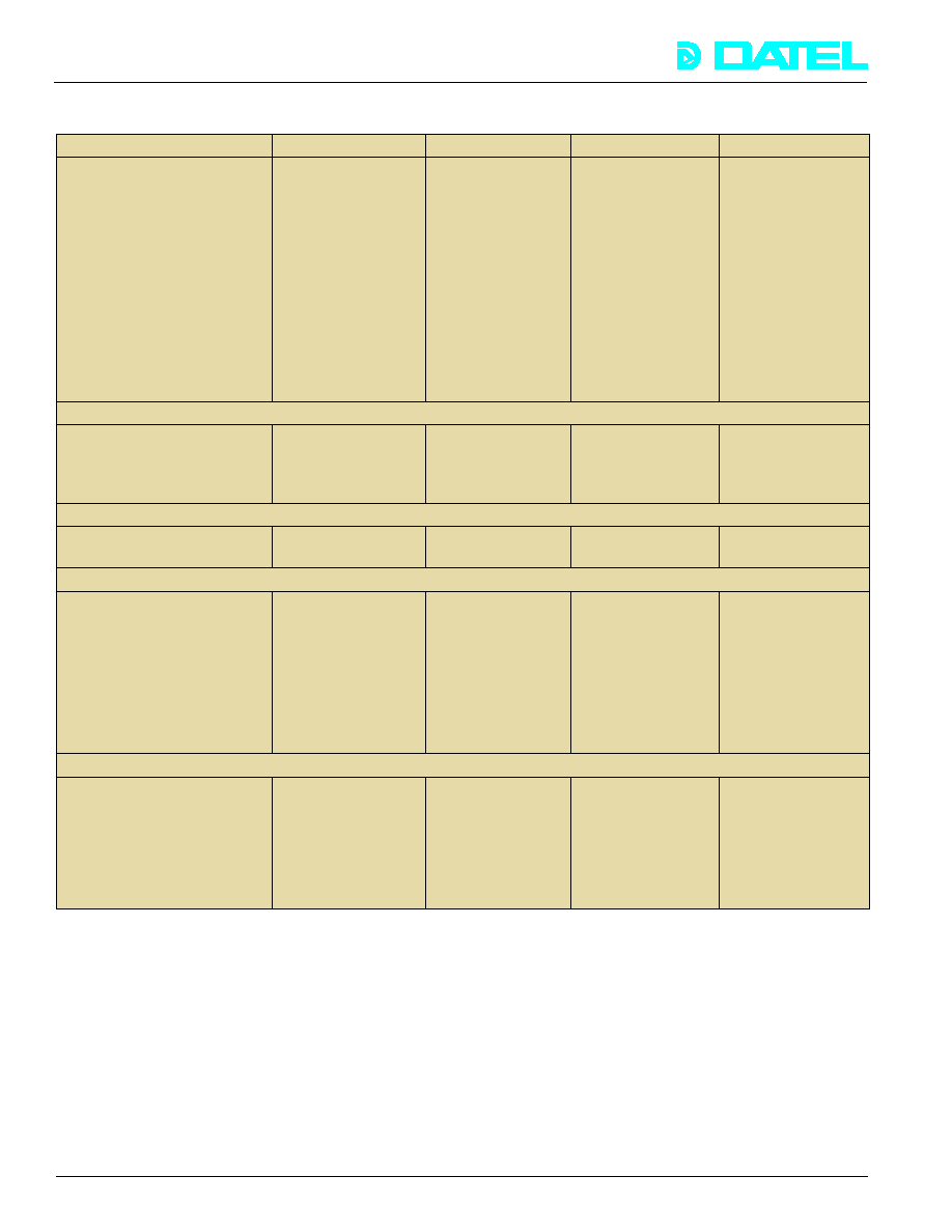
FUNCTIONAL SPECIFICATIONS
(Typical at +25∞C, dynamic conditions, gain = 1, unless noted)
PC-414K
2 Simultaneous
(two A/D's)
Limited Differential
0 to +10 V, ±5 V
(separate models)
±15 V
--
±1 V
1 k
50 ns
10 ns
±7 ps
12 bits
200 ns
±2
±1
±0.1
±0.3
5 MHz
5 MHz/ch.
≠68 dB
PC-414G
2 Simultaneous
(two A/D's)
Single Ended
±5 V or
0 to +10 V
(separate models)
±15 V
2 µs
--
1 M
350 ns [Note 11]
20 ns
±70 ps
14 bits
500 ns
±1.5
±1
±0.3
±0.3
1 MHz
1 MHz/chan.
(2 chans.)
≠80 dB
PC-414H
1
(single A/D)
Differential
±5 V
(other ranges
special order)
±15 V
1 µs
±1 V
2 k
35 ns
±10 ns
3 ps rms
12 bits
100 ns
±1.5
±1
±1
±1
10 MHz
--
≠65 dB
PC-414J
8 Simultaneous A/D's
[Note 8]
Single Ended
±5 V, ±10 V
[Note 13]
±15 V
3 µs
--
8 k
(bipolar)
400 ns
--
--
12 bits
2 µs [Note 12]
±1
±1
[Footnote 10]
[Footnote 10]
400 kHz
250kHz/chan.**
≠75 dB
SAMPLE/HOLD
A/D CONVERTER
SYSTEM DC CHARACTERISTICS [Note 7]
SYSTEM DYNAMIC PERFORMANCE [Note 2]
**A 380 KHz per channel option is available on special order.
82
PC-414
Æ
Æ
DATEL, Inc., Mansfield, MA 02048 (USA)
∑
Tel: (508)339-3000, (800)233-2765 Fax: (508)339-6356
∑
Email: sales@datel.com
∑
Internet: www.datel.com
FUNCTIONAL SPECIFICATIONS
(Typical at +25∞C, dynamic conditions, gain = 1, unless noted)
ANALOG INPUTS
Number of Channels
Input Configuration
(non-isolated) [Note 19]
Full Scale Input Ranges
(user-selectable) (gain = 1)
[Notes 1 & 16]
Input Overvoltage
(no damage, power on)
Overvoltage Recovery
Time, maximum
Common Mode Voltage
Range, maximum
Input Impedance [Notes 6 &10]
Acquisition Time
(FSR step to 0.01% of FSR, max.)
Aperture Delay
Aperture Delay Uncertainty
Resolution
Conversion Period
Integral Non-linearity
(LSB of FSR)
Differential Non-linearity
(LSB of FSR)
Full Scale Temperature
Coefficient (LSB per ∞C)
Zero or Offset
Temperature Coefficient
(LSB per ∞C)
Throughput to FIFO
(single channel, gain = 1)
Throughput to FIFO
(sequential channels,
gain = 1)
Total Harmonic Distortion
[Note 3]
PC-414L
16 Simultaneous
A/D's
Single Ended
±5 V, ±10 V,
(user selectable)
[Note 13]
±15 V
--
--
8 k
400 ns
--
--
12 bits
2 µs [Note 12]
±2
±1
[Note 10]
[Note 10]
400 kHz
190 kHz/chan.
-75 dB
PC-414M
4 Simultaneous
A/D's
Single Ended
±10 V
±12 V
--
--
10 M
--
--
--
16 bits
5 µs [Note 12]
±4
±3
±1
±1
200 kHz
200 kHz/chan.
-83 dB
PC-414P
4 Simultaneous
A/D's
Single Ended
±2.5 V or
0 to +5 V
(user selectable)
±7 V
--
--
1000
--
--
--
14 bits
400 ns [Note 12]
±3
±1.5
±0.5
±0.5
3 MHz* min.
2.5 MHz/chan.
-75 dB
PC-414N
2 Simultaneous
A/D's
Single Ended
±2.5 V
±15V
--
--
10 M
or 50
35 ns
±10 ns
5 ps
14 bits
200 ns [Note 12]
±1
±1
±0.5
±0.5
5 MHz
5 MHz/chan.
-75 dB
SAMPLE/HOLD
A/D CONVERTER
SYSTEM DYNAMIC PERFORMANCE [Note 2]
SYSTEM DC CHARACTERISTICS [Note 7]
* The sample rate to published specifications is 3 MHz. The A/D is functional to 5 MHz. Valid data output per channel is delayed
by 4 samples after the start of the sample clock. Please make note of this for products such as the PC-414P, PC-430P, and
DVME-614P which use non-continuous A/D sampling. Data output is pipelined meaning that the first four samples per channel
should be discarded. For all 4 channels, discard 16 samples. The design is intended for semi-continuous sampling of wideband
signals and is less suitable for low speed data acquisition. Approximately 5 dB SFDR improvement can be achieved by directly
connecting an external A/D sample clock. Contact DATEL for details.
83


