 | –≠–ª–µ–∫—Ç—Ä–æ–Ω–Ω—ã–π –∫–æ–º–ø–æ–Ω–µ–Ω—Ç: PC-423A/B | –°–∫–∞—á–∞—Ç—å:  PDF PDF  ZIP ZIP |

PC-423
Streaming Analog Output and
Digital Pattern Generator with FIFO
FEATURES
∑∑
∑∑
∑
Four, high-performance analog outputs
∑∑
∑∑
∑
Four, high-speed, 16-bit digital pattern ports
∑∑
∑∑
∑
Dual-port FIFO memory on each channel
∑∑
∑∑
∑
12-bit D/A's, update rates to 1MHz
∑∑
∑∑
∑
Selectable simultaneous or single channel modes
∑∑
∑∑
∑
Low-pass, reconstruction filter per channel
∑∑
∑∑
∑
Programmable timer and external clock control
∑∑
∑∑
∑
Windows
Æ
, Windows 95/98
Æ
, DOS
Æ
, and Pentium
Æ
compatible
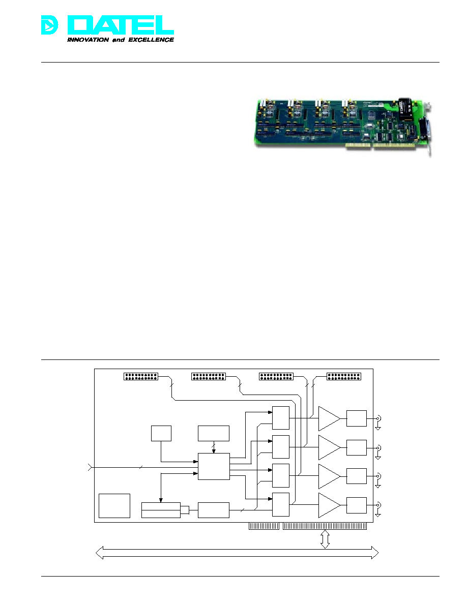
The PC-423 is a four-channel, streaming analog output and
digital pattern generator board for IBM-PC/AT (ISA), EISA bus
and compatible computers. It includes a dual ported First-In-First-
Out (FIFO) memory bank on each channel to allow non-stop,
continuous data streaming and waveform generation without any
lost samples. Outputs can be updated simultaneously or
independently, and channels can be selectively enabled and
disabled under host software control. Applications include
precision phase-synchronous analog and digital signal generation
for system simulation, automatic test equipment, communications,
and process control.
Unbuffered output boards require continuous host service. On the
PC-423, complete waveform segments are downloaded into the
FIFO memory on each channel. Using a local programmable
clock or an external clock, input data sequencing and waveform
generation continues without host intervention as long as there is
data in the FIFO. The host is not slaved to the PC-423 during this
time and is free to service other tasks such as data processing,
data display, and disk transfers. New data-load requests are
software selectable as a host polled status flag or as an interrupt.
Under program control, all FIFO's can be updated concurrently
with new data or each FIFO can be loaded individually. This
unique design allows uninterrupted data streaming and waveform
synthesis while new data is simultaneously loaded by the host.
Æ
Æ
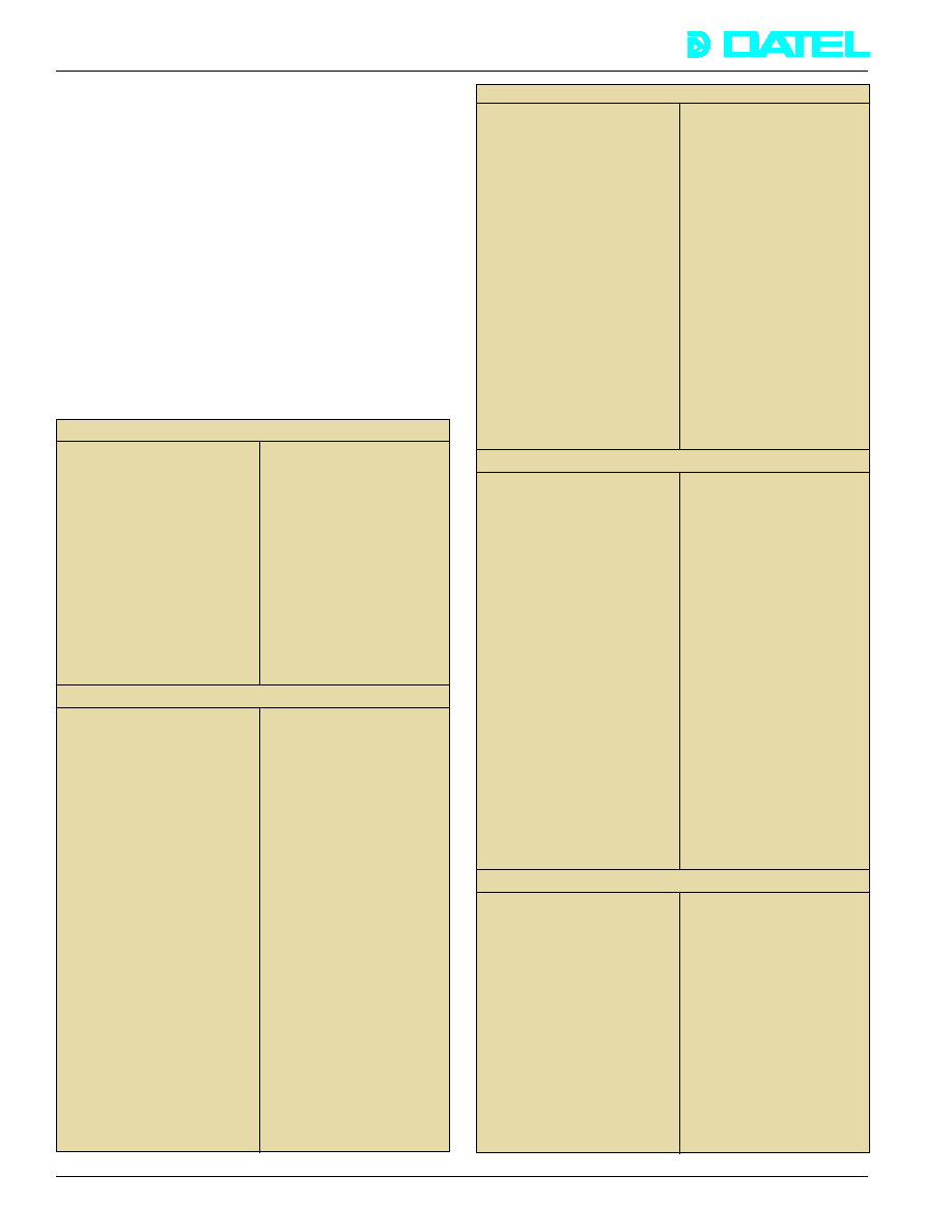
Figure 1. Functional Block Diagram
For high-speed digital pattern generation in test and control
applications, the PC-423 has four 16-bit digital output ports.
These ports are accessible through dual-row internal header
connectors that are suitable for industry-standard flat cable
connections. Each port includes a data clock for external
synchronization. Data rates from the FIFO through the digital
ports are individually software-selectable via internal or
external clocks. Update rates to 5MHz are possible for the
digital ports. The digital port and the analog output on each
channel share the same FIFO memory.
The data rate to the DAC and digital ports can be selected via a
local timer or an external clock input. An 82C54 programmable
counter/timer provides a 16-bit software-selectable divide ratio to
a local 10MHz stabilized crystal oscillator. This ensures very high
accuracy and low noise on the analog outputs, and eliminates
clock and data jitter on the digital ports. A separate clock can be
used to drive each channel. Application synchronization can be
achieved by using an external clock input. The external clock
drives the D/A and the digital port directly. External clocking
allows channel expansion and synchronization when running
multiple PC-423's simultaneously.
FIFO
DAC
FIFO
DAC
FIFO
DAC
FIFO
DAC
Timebase
Control
PC Bus
Interface
2 x 82C54
Timers
10MHz
Control
I/O Addressing
Filter
Filter
Filter
Filter
DC/DC
Converter
External Clocks
Digital Pattern
Port 0
Digital Pattern
Port 1
Digital Pattern
Port 2
Digital Pattern
Port 3
16
16
16
16
16
4
Control
and Data
PC/AT (ISA) Bus
Clk 3
Clk 2
Clk 1
Clk 0
Analog
Output 3
Analog
Output 2
Analog
Output 1
Analog
Output 0
DATEL, Inc., Mansfield, MA 02048 (USA)
∑
Tel: (508)339-3000, (800)233-2765 Fax: (508)339-6356
∑
Email: sales@datel.com
∑
Internet: www.datel.com
129

Æ
Æ
PC-423
DATEL, Inc., Mansfield, MA 02048 (USA)
∑
Tel: (508)339-3000, (800)233-2765 Fax: (508)339-6356
∑
Email: sales@datel.com
∑
Internet: www.datel.com
A low-pass filter on each analog output eliminates high-
frequency system noise components from the output
waveforms. Wideband output amplifiers minimize distortion.
The full scale analog output voltage range is selectable per
channel as ±5V or ±10V, and each channel will deliver up to 5
milliamps. The output signal connector includes capacitively
coupled voltage outputs for each channel. Offset and gain
adjustments on each channel allow optional DAC recalibration.
The PC-423 is configured on a full size PC/AT bus (ISA bus)
board, and it occupies one motherboard slot. Due to its
slimline design, the PC-423 does not overlay adjacent slots.
The board is completely contained inside of the host PC. The
analog outputs are easily accessible through a rear panel
DB-25 connector. DATEL's optional PC-490B screw terminal
block facilitates field wiring.
ANALOG OUTPUTS
Number of Channels
Four
Output Channel Configuration
Single-ended, non-isolated
D/A Converter Resolution
12 bits
Channel Update Rates
333kHz max. for full scale
changes, 1MHz max. for
LSB increments. All
channels can be updated
individually or simultaneously.
Output Voltage Ranges
±5V or ±10V, selectable
per channel
Output Current
±5 milliamps max.
Output Impedance
1 Ohm
Output Protection
Short-circuit protection to
ground
Settling Time
3 microseconds (to ±0.01%
FSR), 1 microsecond for
LSB increments
Linearity Error
±0.25 LSB max. This is the
maximum deviation of the
actual DAC output from the
ideal value for a given
digital input code.
Differential Nonlinearity
±0.5 LSB max. This is a
measure of variation in analog
output, normalized to full
scale, associated with a 1LSB
change in input code.
Monotonicity
Monotonic over the full
operating temperature
range. The analog output
either increases or remains
constant for increasing
digital inputs, thus ensuring
that the output is always a
nondecreasing function of
the input.
Slew Rate
10V per microsecond min.
Output Filter
Low-pass, single-pole filter
per channel. ≠3dB cutoff at
5MHz.
FUNCTIONAL SPECIFICATIONS
(Typical at +25∞C, dynamic conditions, unless otherwise noted)
ANALOG OUTPUT PERFORMANCE
DIGITAL PATTERN PORTS
Number of Ports
Four. Each port contains
16 data bits, data clock,
and digital ground.
Data Port Width
Sixteen digital bits
Data Source
One FIFO on each channel.
The FIFO is shared by the
analog output and the
digital port on each
channel.
Update Rates (FIFO to DAC)
5MHz max. The rate is
programmable via internal
timer or external clock
inputs. See app. notes.
Port Loading
5 CMOS/TTL loads max.
Power-up and Reset State
High impedance (tri-stated)
Port Connector Type
Twenty pin, dual-row
header connector, mounted
internally on the board.
Connection made using
industry-standard flat cable
Memory Type
First-In, First-Out (FIFO).
Dual ported for
simultaneous reading and
writing without data flow
interruption.
FIFO Capacity
1k or 8k samples per
channel. Each sample is 2
bytes wide.
FIFO Access Time
50 nanoseconds max.
FIFO Control Flags
Empty, half full, and full
flags per channel. All flags
are echoed in the Status
Register for host polling.
The FIFO half full flag can
be selected as a host
interrupt.
FIFO Reset Operation
Software reset clears all
data from the FIFO on the
selected channel.
Data Coding
Right justified offset binary
for the D/A channels. 16-bit
raw binary data when using
the digital ports.
Update Sources
Internal programmable
clock or external TTL clock
input. The clock source
and clock rate are
selectable per channel.
Clock Sharing
All channels can share one
common internal or
external clock.
Local Timer
16-bit, 82C54 programmable
timer per channel driven by
10MHz stabilized crystal
oscillator
Local Timer Frequency Range
152.59Hz to 5MHz,
software programmable via
82C54.
DATA MEMORY
TIMING
130

Æ
Æ
PC-423
DATEL, Inc., Mansfield, MA 02048 (USA)
∑
Tel: (508)339-3000, (800)233-2765 Fax: (508)339-6356
∑
Email: sales@datel.com
∑
Internet: www.datel.com
HOST INTERFACE
Architecture
I/O mapped, pluggable into
IBM-PC/AT, EISA bus and
compatibles
I/O Mapping
Decodes sixteen, 16-bit I/O
registers using host
address lines A9 through
A4. Address lines A3...A0
are locally decoded for
individual register access.
I/O Address Range
One of 16 predefined I/O
addresses between 100
hex and 3A0 hex
Data Bus
16-bit I/O transfers. All
data is right justified.
Interrupt Request
One line, software-
selectable on IRQ 7, 9, 10,
11, 12, 14, or 15
Interrupt Source
FIFO less than half full,
triggered by the FIFO Half
Full (HF) flag on a selected
channel. This is a request
for new data to be loaded.
Control/Status Functions
DAC channel select, FIFO
data loading, FIFO reset,
host interrupt enable,
interrupt source select,
interrupt level select,
82C54 timer programming,
FIFO empty, half-full, and
full flags status monitoring
Host Bus Power Consumption
+5V at 1A max.
Operating Temperature Range
0 to +60∞C
Storage Temperature
≠25 to +80∞C
Relative Humidity
10% to 90%, non-condensing
Altitude
0 to 10,000 feet (0 to 3047m)
Form Factor
Full size, PC/AT bus (ISA
bus) board. Occupies one
single slot.
Outline Dimensions
4.5" x 13.31" x 0.5"
(11.43 x 33.81 x 1.59cm)
Weight
12 ounces (0.35kg)
MISCELLANEOUS
Some applications require custom software. For these, the
complete source code to PC-423WIN is available -- called
PC-423WINS. This code was developed using Borland's
Delphi
Æ
visual programming language. The dynamic link
library (DLL ) is written in C. All PC-423's are shipped with a
free diskette and a comprehensive user's manual. The
diskette contains a library of ANSI standard C functions to
help programmers develop their own software. Together with
some additional simple example programs, the user's manual
contains detailed register-programming, hardware-operation,
and circuit-timing information.
I/O REGISTER MAP
(The PC-423 user manual contains comprehensive
programming information and detailed register descriptions.)
The PC-423 is mapped into the host computer's I/O address
space as a block of sixteen registers. The I/O base address is
switch selectable as one of sixteen pre-defined settings
between 100 hex and 3A0 hex, on 16-bit boundaries. Base
address selection avoids hardware contention and allows
multiple PC-423 boards to be installed in the same host
concurrently. Each register on the board is located at a fixed
offset from the I/O base.
Table 1. PC-423 I/O Register Map
I/O Address
Direction
Description
BASE+0
Write only
Command Register
BASE+0
Read only
Status Register
BASE+2
Write only
FIFO Reset Register
BASE+4
Write only
FIFO Data Register
BASE+8,9,...,F
Read/Write
82C54 Control and
Data Registers
REGISTER OVERVIEW
At power up or PC bus reset, all registers contain 0, all FIFO's
are cleared, and the digital ports are tri-stated. All register
data is right justified to facilitate programming in 80x86 and
Pentium
Æ
processor environments. Registers can be
programmed in any sequence as long as the Command
Register is last.
Command Register (Write I/O Base + 0)
The Command Register configures PC-423 operation. Under
software control, it enables or disables one or more channels
and chooses individual or multiple FIFO's for reset. It selects
either an internal or external clock for each channel. During
signal generation, the Command Register steers blocks of
data from the host to the requesting FIFO. When using host
interrupts to load new data, the interrupt source and interrupt
level are specified in the Command Register.
Status Register (Read I/O Base + 0)
This register echoes the status of the FIFO empty, half full,
and full flags for each channel. FIFO empty indicates a data
underflow condition, i.e. the data update rate on the PC-423 is
too high for the host to keep up with. When this occurs, the
output waveforms will be discontinuous. When the FIFO on
any channel gets less than half full, new data must be loaded
to that channel by the host. Loading more data than the FIFO
can store will result in lost data. The FIFO indicates such an
overflow condition.
PC-423WIN Software
PC-423WIN brings intuitive control to your test and engineering
applications. It is a powerful, easy to use Windows
Æ
/Windows 95
Æ
setup and signal-generation software system. It configures
PC-423 hardware, starts signal generation, and continues to steer
data from the host to the FIFO's in real time. Data files can be
loaded from disk into ring buffers in host memory for high-speed,
non-stop, continuous analog and digital signal generation. Infinitely
long baseline records can be streamed directly from huge disk files.
PC-423WIN selects between single-channel or simultaneous-
channel update modes. Using the mouse, channels can be
selectively enabled or disabled, and internal or external clock
combinations can be selected per channel. Data update rates
on each channel are software selectable. During signal
generation, new data is loaded from the host to the FIFO's
without data flow interruption on the analog or digital ports.
131

Æ
Æ
PC-423
DATEL, Inc., Mansfield, MA 02048 (USA)
∑
Tel: (508)339-3000, (800)233-2765 Fax: (508)339-6356
∑
Email: sales@datel.com
∑
Internet: www.datel.com
Application Notes
Blocks of data are transferred to the PC-423 when the FIFO's
become less than half full. The requesting FIFO posts a status
flag to indicate this "data starved" condition. If all channels are
being updated by the same clock, then all FIFO's can be
loaded with new data when one generates the request. A new
data-load request for a particular channel can be configured
as a host interrupt. The FIFO's are dual ported to allow
simultaneous data loading by the host while the D/A and
digital ports continue to be updated without interruption. This
allows non-stop, continuous data streaming without lost
samples. Typical ISA bus transfers using optimized code is
about one megasample per second under MS-DOS.
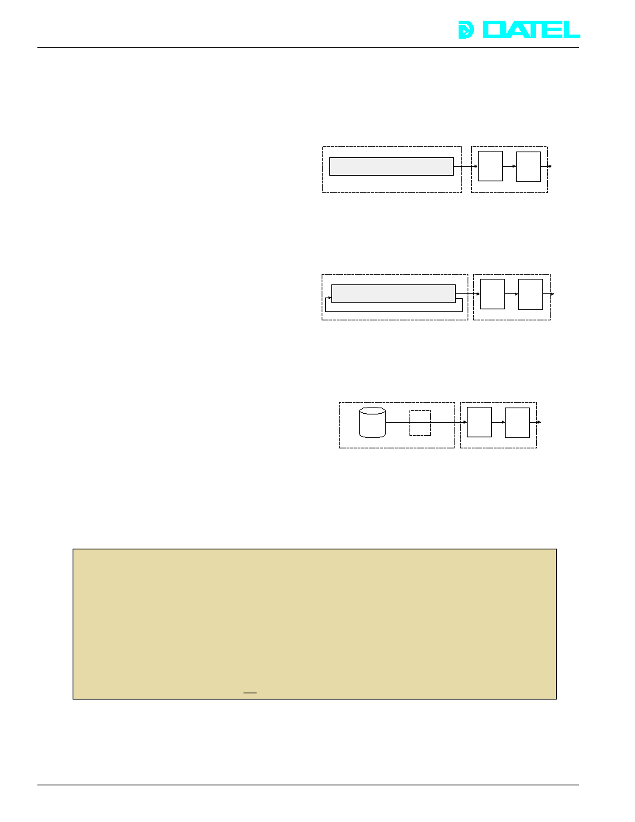
There are three main data transfer modes on the PC-423.
1) Linear buffering -- allocate a large contiguous buffer in host
memory from which data is loaded in blocks to the
PC-423 FIFO's for a fixed time. The time is defined by the
length of the buffer and the PC-423 update rate. Applications
include high-speed, non-periodic waveform generation,
process control, and simulation.
Figure 2. Linear Buffering
2) Ring buffering -- allocate a circular buffer in host memory
from which data can be continuously loaded to the PC-423
FIFO's for long periods of time. Applications include periodic
signal generation, digital pattern testing, and ATE.
Figure 3. Ring Buffering
3) Disk streaming -- transfer blocks of data to the PC-423
directly from huge files on the hard disk. Applications include
long baseline signal generation, audio playback, and arbitrary
waveform synthesis.
Figure 4. Disk Streaming
FIFO Reset Register (Write I/O Base + 2)
Writing this register clears the FIFO on the selected channel.
The channel is software selectable in the Command Register,
or all FIFO's can be cleared simultaneously. FIFO resetting
should be done during board configuration only. Resetting a
FIFO during signal generation will result in discontinuities in
the output waveforms.
FIFO Data Register (Write I/O Base + 4)
Data for all PC-423 channels is loaded into this register, the
Command Register steers this data to the correct FIFO bank.
Each FIFO is 16-bits wide. Only the lower 12 bits of the FIFO
Data Register are used by the D/A converters, the upper four
bits are ignored. The data coding for the D/A converters is
offset binary and the data is right justified. Each digital port
contains all sixteen FIFO bits. No FIFO memory addressing is
necessary. Simply load new data into this I/O register and the
PC-423 hardware takes care of the rest.
Timer Register (Read/Write I/O BASE + 8, 9, ..., F)
Internal clock rates are programmable via two 82C54 timers.
Each timer has three 16-bit counters to programmably divide
the local 10MHz crystal oscillator clock. A separate counter
drives each channel allowing different clock rates for each.
Host PC
FIFO
D/A
or
Digital
Port
Contiguous, linear data
buffer in host memory
PC-423
Output
Host PC
FIFO
D/A
or
Digital
Port
Circular buffer in
host memory
PC-423
Output
Continuously recirculates from end to start of buffer
Host PC
FIFO
D/A
or
Digital
Port
PC-423
Output
Disk
Buffer
Disk
ORDERING GUIDE
Model
Description
PC-423A
4-channel, FIFO buffered analog and digital output board. Uses 1k sample FIFO's per channel.
Includes free driver diskette and comprehensive user manual.
PC-423B
4-channel, FIFO buffered analog and digital output board. Uses 8k sample FIFO's per channel.
Includes free driver diskette and comprehensive user manual.
PC-423WIN
Board configuration and signal generator software. Runs under Windows
Æ
3.1 and Windows 95
Æ
.
PC-423WINS
Complete source code for PC-423WIN. Developed using Borland's Delphi
Æ
DLL written in C.
PC-490B
Screw terminal to DB-25 connector block to facilitate field wiring.
PC-423LV
Virtual insturment set (binary executables only) to run PC-423 under LabVIEW
Æ
. Purchase
LabVIEW separately from National Instruments.
PC-423LVS
Source code to PC-423LV.
PC-423WIN/WINS software is
not included with the board. If desired, please add to your order.
Windows, Windows 95, and DOS are a trademark of Microsoft
Pentium is a trademark of Intel
LabVIEW is a trademark of National Instruments
132


