PC-440
32-Channel, Analog Input
Expansion Board for IBM-PC
PRODUCT DATA
Æ
Æ
FEATURES
∑∑
∑∑
∑
32 single-ended/16 differential expansion channels
∑∑
∑∑
∑
Use with DATEL's PC-411/PC-412 boards
∑∑
∑∑
∑
Cascadable to 512 channels (SE) or 256 channels (D)
∑∑
∑∑
∑
Channel select by PC bus or digital input port
∑∑
∑∑
∑
10 microseconds settling time
∑∑
∑∑
∑
Local programmable gain amplifier (PGA)
∑∑
∑∑
∑
Optional signal conditioning pads
∑∑
∑∑
∑
On-board DC/DC power converter
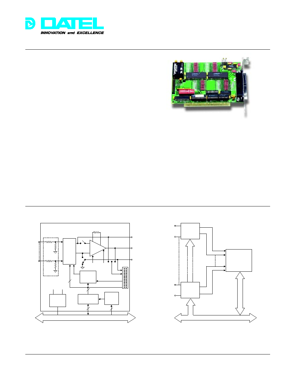
The PC-440 is a channel expansion board for use with any
A/D board on IBM-PC, PC/XT, PC/AT, EISA bus, and
compatible computers. It interfaces to DATEL's PC-411/412
family of multifunction I/O boards. Each PC-440 offers 32
single-ended or 16 differential analog input channel expansion
capability and multiple boards can be cascaded to achieve a
very high channel expansion for one A/D board. Each
channel in the system is multiplexed down to the A/D
converter on the parent A/D board where it is digitized for
further processing, storage, or display on the host computer.
Base address switches select each board's I/O address. Up
to eight PC-440's can be mapped to one I/O base address
location when operating in single-ended mode, up to 16 in
differential mode. Since there are 256 individual I/O address
locations decoded by the PC-440, the total number of
externally multiplexed channels per A/D board is extremely
large. Channel addresses can be generated by software on
the host computer or can be loaded from the digital input port.
For channel scan applications, the channel address can be
advanced by a software strobe or an external TTL input.
Figure 1. PC-440 Simplified Block Diagram
Figure 2. Interfacing PC-440 to A/D Board
The input voltage range is ±10 Volts. Optional circuit pads on
each channel may be configured for other voltage ranges, for
current loop inputs, or for analog signal conditioning. The on-
board Programmable Gain Amplifier (PGA) is user-selectable
for gains from 1 to 100 to accommodate low level inputs. It
may be bypassed to minimize channel settling delays. A local
dc-to-dc converter supplies all the analog power required from
the PC/XT/AT bus +5 Volt line.
The PC-440 is configured on a half-size PC/XT/AT ISA bus
card and plugs directly into the host computer bus via the I/O
expansion connectors. Analog signal field connections are
made through a 37-pin "D-type" connector on the rear
mounting bracket. Connections are made to the digital input
port via a 26-pin, male header connector mounted internally
on the PC-440. This connector also contains the analog
output signals from the multiplexer and the PGA.
PC/XT/AT Bus
Gain
Resistor
PGA
Analog
MUX
OUT HI
(P2)
OUT LO
(P2)
MUX
Decode
Logic
Channel Advance
Input
Port
Header
Connector
(P3)
P3
Base
Address
Select
I/O Bus
Interface
DC/DC
Converter
+15V
-15V
+5V
Signal
Conditioning
Pads
Analog
Input
Channels
(32 SE/
8 Diff)
on rear
panel
connector
(P2)
Channel Address 0-7
AMP OUT
(P2)
En
Offset
Adjust
Gain
Adjust
+
≠
PC/XT/AT BUS
PC-440
A/D Board
(PC-411/412)
PC-440
Analog
Input
Channels
HI
LO
HI
LO
Channel
Address
0-7
DATEL, Inc., Mansfield, MA 02048 (USA)
∑
Tel: (508)339-3000, (800)233-2765 Fax: (508)339-6356
∑
Email: sales@datel.com
∑
Internet: www.datel.com
91

PC-422
Æ
Æ
DATEL, Inc., Mansfield, MA 02048 (USA)
∑
Tel: (508)339-3000, (800)233-2765 Fax: (508)339-6356
∑
Email: sales@datel.com
∑
Internet: www.datel.com
ANALOG INPUTS
Number of Channels
32 single-ended or 16
differential, selected by DIP
switch
Input Voltage Range
±10 Volts
Configuration
Non-isolated break before make
Overvoltage
±20V max. sustained no
damage
Channel OFF Leakage
±30 picoAmps
Channel ON Bias Current
±50 nanoAmps
Channel OFF Input
Capacitance
5 picoFarads
Linearity
±0.01%
Crosstalk (1kHz FS)
±0.005%
Settling Time (no PGA)
2 microseconds maximum
Settling Time to 0.01%
PGA Gain = 1
10 microseconds maximum
Settling Time to 0.1%
PGA Gain = 100
40 microseconds maximum
Programmable Gain
1 to 100, selected with user-
installed precision resistor.
Same gain fixed for all channels.
Temp. Coefficient of Gain
±20ppm of FSR per ∞C
Temp. Coefficient of Zero
±15ppm of FSR per ∞C
Channel Address
8-bit address code may be
loaded from bus or digital
input port.
Address Page Offset
Channel banks may be
selected per board - up to 8
SE, up to 16 DIFF. Multiple
PC-440's can share the same
I/O base address. Deselected
PC-440's disconnect their
channel MUX to share an
output line.
Channel Advance
1. Software strobe or
2. External TTL input, active low
Digital Input Port
26-pin header connector. All
digital lines are TTL levels.
The port contains two analog
outputs (HI and LO), analog
common, amplifier output, 8
channel address inputs, 1
channel advance input, and 1
digital ground.
FUNCTIONAL SPECIFICATIONS
(Typical at +25∞C unless otherwise noted)
PERFORMANCE
PC BUS INTERFACE
Architecture
Decodes two word-wide I/O
registers using address lines A9-
A0. Highest base address is
3F0h. May be accessed with
either byte or word I/O
instructions.
Data Bus Width
8 bits
Compatibility
May be installed in IBM-PC,
XT, AT, EISA, and compatibles
Connectors
PC bus, 62-pin edgeboard.
Input port, 26-pin header
suitable for flat cable.
Switches
Two Dual Inline Package (DIP):
I/O base address, page map
offset, PGA in/out, single-
ended/differential modes
Adjustments
PGA Offset and Gain
Operating Temp. Range
0 to +60∞C
Storage Temp. Range
-25 to +85∞C
Relative Humidity
10% to 90%, non-condensing
Altitude
0 to 10,000 feet
Power Required
+5Vdc and 1 Amp max. from
PC bus
Outline Dimensions
4.2 x 5.3 x 0.5 inches
(10.5 x 13.3 x 1.3 cm)
Weight
5 ounces (195 grams)
DIGITAL CONTROL
MISCELLANEOUS
PROGRAMMING
The PC-440 I/O base address may be selected up to 3F0 hex
on 4 byte boundaries. The board decodes two 16-bit I/O
registers as follows:
I/O Address
Direction
Description
(Hex)
BASE + 0
Write
Channel Address Register
BASE + 2
Write
Channel Advance Register
If multiple boards share the same base address, channel banks
are selected with on-board DIP switches; details in user manual.
CHANNEL ADDRESS REGISTER (Write BASE + 0)
15 . . . 8
7 . . . 0
Not Used
Channel Address
CHANNEL ADVANCE REGISTER (Write BASE + 2)
15
14 . . . . . . . . 1
0
X
X . . . . . . . . X
X
ORDERING INFORMATION
PC-440
Analog input channel expander board. Includes
user manual.
PC-490C
37-pin screw termination
IBM is a trademark of IBM Corp.
92