 | –≠–ª–µ–∫—Ç—Ä–æ–Ω–Ω—ã–π –∫–æ–º–ø–æ–Ω–µ–Ω—Ç: PC-462SET | –°–∫–∞—á–∞—Ç—å:  PDF PDF  ZIP ZIP |
PC-462
Precision Programmable
Power Supply Board
FEATURES
∑ 4 independently programmable, precision voltage/
current outputs
∑ Remote sensing for all supplies
∑ All channels fully isolated from PC/ATbus
∑ Output current limits
∑ Real time voltage and current monitoring
∑ 4 general purpose analog inputs
∑ 2 isolated digital inputs
∑ 2 isolated relay driver outputs - MOSFET switches
∑ Comprehensive software, free driver library
Designed for low-cost, medium power source applications, the
PC-462 is a high-precision, programmable power supple and
sensing board for IBM-PC/AT, PS-30, EISAbus and compatible
computers. Four output channels are individually
programmable for ranges of 0 to +6.1425V and 0 to
-6.1425V at 1A, as well as 0 to +20.475V and 0 to -20.475V at
250 milliamps. It is ideal for applications where highly
accurate, very stable DC voltage and current sources are
required, with low ripple and low noise characteristics. All
input and output channels provide 250Vrms isolation from the
PC/ATbus. Combined with comprehensive, graphic-intensive
control software, this quad output supply card is easily
integrated into most automated test and benchtop power
supply applications.
Æ
Æ
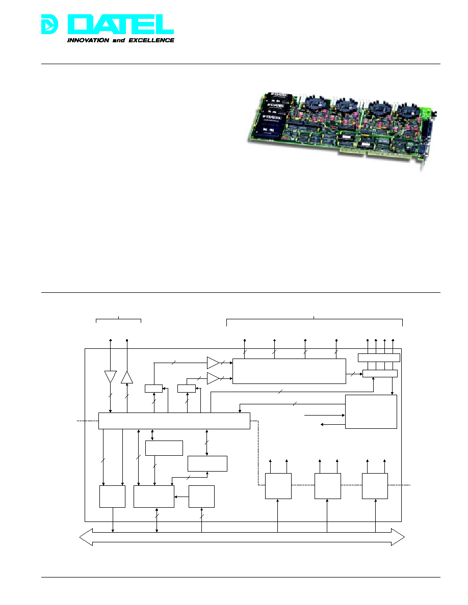
Figure 1. Simplified Block Diagram
For dynamic test sequences, the host PC can update all four
output channels in real time. Voltage and current output levels
are continuously monitored by an on-board, 12-bit A/D
converter. A rear panel connector provides an additional 4
auxilliary input channels for general purpose use. The input
range is ±5.12V but component pads on all of the channels
allow for user-selectable ranges as well as current loop inputs
and signal filtering. These channels are fully isolated from the
PC/ATbus and are ideal for monitoring external voltage/current
conditions in adaptive test applications.
2
2
D / A
C o n v e r t e r s
1 2
1 2
C u r r e n t S e n s e
A m p l i f i c a t i o n
M U X
T r a c k i n g
A / D
C o n v e r t e r
2
2
I n t e r r u p t
R e q u e s t
C o n t r o l a n d
S t a t u s R e g i s t e r s
I / O B u s
I n t e r f a c e
B a s e
A d d r e s s
S e l e c t
D i g i t a l
I n 0 , 1
+ 9 V
9 V
+ 2 4 V
+ 1 2 V
2 4 V
1 2 V
+ 5 V
+ 1 2 V
+ 1 2 V
P C / A T B u s
P 2 C o n n e c t o r
2 M O S F E T O u t p u t s
2 D i g i t a l I n p u t s / E x t . T r i g g e r I n
P 1 C o n n e c t o r
+ 6 . 1 4 4 V
a n d S e n s e
6 . 1 4 4 V
a n d S e n s e
+ 2 0 . 4 8 V
a n d S e n s e
2 0 . 4 8 V
a n d S e n s e
V / I
( G e n e r a l P u r p o s e )
2
2
2
2
C h a n n e l A d d r e s s
4
E O C
A / D D a t a
S T C O N V
P a r a l l e l t o S e r i a l
S e r i a l t o P a r a l l e l
2
E O C
A n a l o g O u t p u t s
I s o l a t i o n
B a r r i e r
H i g h V o l t a g e
O p t o - I s o l a t o r s
D C / D C
P o w e r
C o n v e r t e r
( I s o l a t e d )
D C / D C
P o w e r
C o n v e r t e r
( I s o l a t e d )
D C / D C
P o w e r
C o n v e r t e r
( I s o l a t e d )
D i g i t a l I / O
A n a l o g I n p u t s
S i g n a l C o n d i t i o n i n g
1 2
DATEL, Inc., Mansfield, MA 02048 (USA)
∑
Tel: (508)339-3000, (800)233-2765 Fax: (508)339-6356
∑
Email: sales@datel.com
∑
Internet: www.datel.com
133
Æ
Æ
PC-462
DATEL, Inc., Mansfield, MA 02048 (USA)
∑
Tel: (508)339-3000, (800)233-2765 Fax: (508)339-6356
∑
Email: sales@datel.com
∑
Internet: www.datel.com
Outputs are protected against overload and short circuit
damage by fixed current limiting circuits. For any overload
condition, the +6.1425V and -6.1425V supplies are limited to
1.2A, while the +20.475V and -20.475V supplies are limited to
300 milliamps. Another protective and very necessary feature
is that at power up all output channels reset to 0V. Remote
voltage sensing permits regulation with respect to the load
eliminating problems associated with lead voltage drops.
Four isolated digital I/O lines are available to monitor and
control external devices. The two input lines may be config-
ured to generate interrupt requests to the host computer
possibly indicating an external error condition or failure and
requesting immediate system attention. One of these lines is
software selectable as an A/D digital trigger input The two
MOSFET output lines can switch up to 300V at 100 milliamps
for an indefinite period of time. These outputs are ideal for
switching heavy external loads such as relays, triacs, etc.
The PC-462 is configured on a full size PC/AT card and it is
completely contained within the host computer. The direct bus
interface increases the output slew rates and decreases the
host response time to read back voltage/current data. All
isolated input and output channels are available on two D-type
connectors on the rear panel. The board is compatible with
most popular programming languages and all data is right
justified to facilitate integer data typing with high level lan-
guages such as C, FORTRAN, Pascal, or Ada. A comprehen-
sive User's Manual details full installation, programming, and
application information.
SOFTWARE
Users have tow options for implementing PC-462 software:
PC-462SET or user written code. PC-462SET is DATEL's
complete solution for setup and real time control of this
programmable power supply board. It is a comprehensive,
easy-to-use, window-driven utility which configures the
hardware, provides a digital multimeter facility on all of the
input and output channels, sets user defined current and
voltage limits, and configures all interrupt and trigger proce-
dures. Written under Microsoft WINDOWS the highly graphic
user interface makes operation and control of the PC-462 a
simple task.
Output voltage/current values may be set via the keyboard or
by using a mouse and on-screen graphic scroll bars. Error
conditions, such as overvoltage or overcurrent, are user
configurable to be displayed on the screen, to sound alarm
bells, or to shut down the system by resetting all outputs to
zero. A system reset key is available for emergencies.
The package consists of a series of pop-up function windows.
Both the size and position of each window can be altered and
multiple windows may be displayed simultaneously. After
configuring the board, real time control and monitoring of the
PC-462 continues while running other foreground processes
on the host computer. This is ideal for running long, dynamic
test sequences where the host PC is required to carry out
other concurrent tasks.
SPECIFICATIONS
(Typical at 25∞C, dynamic conditions, unless noted)
ANALOG OUTPUTS
Number of Channels
4
Output Configuration
Single-ended, common
isolated analog ground
Full Scale Output Ranges
OUT 1 0 to +6.1425V @ 1A
(See Notes 1 & 4)
OUT 2 0 to -6.1425V @ 1A
OUT 3 0 to +20.475V @250mA
OUT 4 0 to -20.475V @ 250mA
Isolation
250Vrms isolation to PC/AT bus
Isolation Resistance
10 Megohms
Output Resolution
12 binary bits
Input Data Coding
Straight binary, right justified
Channel Addressing Mode
Random access via host
software
Isolation Capacitive
Coupling
850 picofarads
Output Voltage Accuracy
OUT 1&2: ±0.05% of full scale
OUT 3 &4: ±0.025% of full scale
Output Setting Time
OUT 1&2: 400µs max.
OUT 3&4: 600µs max.
Output Voltage Slew Rate
1V per µs into 1µF load
Output Noise,
OUT 1&2: 2mV max (half load)
dc to 10kHz
OUT 3&4: 1mV max (half load)
OUT 1&2: 5mV max (full load)
OUT 3&4: 2mV max (full load)
Output Current Limit
OUT 1&2: 1.2 Amps max.
OUT 3&4: 300mA max.
For custom applications, the User's Manual contains detailed
register and timing information as well as example software
routines necessary to help users to develop their own code - in
any programming language. The PC-462 is supplied with a low-
level device driver library written in C and supplied on MS-DOS
diskettes. The library may be incorporated into user programs
and used for configuring and controlling the PC-462. Also, the
complete source code listing (PC-462SRC) for PC-462SET is
available from DATEL on 3.5" MS-DOS diskettes tofurther
facilitate software development.
OUTPUT PERFORMANCE
134
Æ
Æ
PC-462
DATEL, Inc., Mansfield, MA 02048 (USA)
∑
Tel: (508)339-3000, (800)233-2765 Fax: (508)339-6356
∑
Email: sales@datel.com
∑
Internet: www.datel.com
OUTPUT PERFORMANCE (Continued)
Output Stability
Unconditionally stable into any load
Transient Response
(Half Load Change)
200 microseconds maximum
Temp. Coefficient
of Gain
±20ppm of FSR per ∞C
Temp. Coefficient
of Offset
±20ppm of FSR per ∞C
Number of Channels
12 dedicated to internal
measurements, 4 general purpose
Dedicated Channels
CH 0
OUT 1 Voltage monitor
CH 1
OUT 1 Current monitor
CH 2
OUT 2 Voltage monitor
CH 3
OUT 2 Current monitor
CH 4
OUT 3 Voltage monitor
CH 5
OUT 3 Current monitor
CH 6
OUT 4 Voltage monitor
CH 7
OUT 4 Current monitor
CH 8
+5.12V Ref. monitor
CH 9
-5.12V Ref. monitor
CH 10 GND
CH 11 GND
General Purpose
External Channels
Channels 12, 13, 14, and 15
Analog Input Range
±5.12V (see Tech Note 2)
Input Configuration
Isolated, 250Vrms channel to
PC/AT bus
DC Accuracy
±0.025% of full scale (plus ±1LSB
at 12 bits)
Input Impedance
(See Tech. Note 3)
10 megohms minimum
Input Bias Current
±500 nanoamps
Input Capacitance
1000 pF in series with 2 k
resistor
Input Overvoltage
±6V sustained max., no damage
Addressing Modes
Random via host software
A/D CONVERTER
Resolution
12 binary bits
Conversion Time
50 microseconds
Output Coding
Straight binary; 11 data bits, 1 sign
bit (MSB)
A/D Trigger Source
Initiated via host software or by
external TTL input
External Trigger Pulse
20µs min., active low. TTL levels
Width
on digital input line 0.
Number or Channels
2
Isolation
250 Vrms to PC/AT bus
Input Current
0 mA OFF, 10 mA ON, TTL levels
Input Bandwidth
50 kHz
Output Type
MOSFET power switches, passive.
Number of Channels
2 channels, high voltage and
current capability for switching
heavy loads
Output Ratings
300V, 100 mA continuous.
External excitation required.
Isolation
250 Vrms to PC/AT bus, MOSFET
switches
Switch ON Resistance
25 Ohms
Switch Time
ON 1 millisecond
OFF 1 millisecond
Architecture
I/O mapped, pluggable to IBM-PC/
AT, PS-30, EISA bus and
compatible computers. Decodes
four 16-bit I/O registers.
I/O Mapping
Decodes I/O address lines A9
through A3. A2..A0 are decoded
on-board for individual register
access. Highest base address is
3F8 hex.
Data Bus
16-bit I/O transfers, all data is right
justified
DIGITAL INPUTS
DIGITAL OUTPUTS
PC-AT BUS INTERFACE
ANALOG INPUTS
135
Æ
Æ
PC-462
DATEL, Inc., Mansfield, MA 02048 (USA)
∑
Tel: (508)339-3000, (800)233-2765 Fax: (508)339-6356
∑
Email: sales@datel.com
∑
Internet: www.datel.com
PC/AT bus INTERFACE (Continued)
PC/AT bus Interrupt
1 line, software selectable on IRQ
10, 11, 12, or 15
Bus Interrupt Sources
Software selectable as:
1. A/D End of Conversion (EOC)
2. Digital input channel 0 low
3. Digital input channel 1 low
Analog Connector, P1
25-pin female, DB-25S connector
on rear mounting bracket for easy
access to precision voltage and
sense outputs and general purpose
analog inputs.
Digital I/O Connector, P2
9-pin female, DB-9s connector on
rear mounting bracket. Includes
+5V system power connection.
Power Requirements
4A max. from PC/AT bus +5V
(See Tech. Note 4)
1.5A max. from PC/AT bus +12V
Operating Temp.
0 to 50∞C
Storage Temp. Range
-25 to 80∞C
Relative Humidity
10% to 90%, non-condensing
Altitude
0 to 10,000 ft (0 to 3047 meters).
Forced cooling is recommended.
Outline Dimensions
4.5" H x 13.31" L x 0.5" W
(11.43 x 33.81 x 1.59 cm),
full size PC/AT board. Uses a
single PC/AT slot.
Weight
0.466kg (1 pound)
TECHNICAL NOTES
1. All outputs reset to 0V at power up. The output voltage
steps on each supply are:
OUT 1 and OUT 2
1.5 millivolts per LSB
OUT 3 and OUT 4
5.0 millivolts per LSB
2. Users can select different voltage ranges for this general
purpose analog input channel by inserting attenuation
resistors into component pads provided. Capacitors
mounted in these pads can provide signal filtering.
Discrete components needed for current loop inputs would
mount in these pads as well.
3. The input impedance of 10 megohms minimum avoids
attenuation errors due to external source resistances.
4. Power requirements are specified with all outputs driving
FULL loads. At full load on all channels, the maximum
total power required is 40 Watts. At half load it is 20 Watts,
and at quarter load 10 Watts, etc. 1.5 Amp maximum
current can be drawn from OUT 1 and OUT 2.
5. Recalibration is recommended at 90 day intervals,
depending on operating conditions.
PROGRAMMING NOTES
(Refer to PC-462 user's Manual for detailed programming
information)
1. Since all registers are I/O mapped, I/O read and write
commands must be used. For example, in C, 'outport' will
write a 16-bit word from that register.
2. When setting a value on an output channel, command and
address information must be written before writing DAC
data.
3. The PC-462 may be programmed in almost any high- or
low-level language. The following example program
illustrates how to set an output channel's value:
#define BASE 0x300 /* User-defined base address*/
#include <stdio.h>
#include <math.h>
main ( )
{
unsigned short channel_addrs_reg, dac_data_reg;
int channel, dac_data;
float volts, full_scale
channel_addrs_reg = BASE + 2;
dac_data_reg = BASE + 4;
printf ("Which channel (0...3) => ");
scanf ("%d, &channel);
printf ("Output voltage => ");
scanf ("%f", &volts);
outport (channel_addrs_reg, channel);
switch (channel) /* Set channel full scale */
{
/* output voltage levels */
case 0:
case1: full_scale = 6.1425;
break;
case 2:
case 3:
full_scale = 20.475;
break;
}
dac_data = (int) (fabs(volts) * 4096.0/full_scale);
outport (dac_data_reg, dac_data) /*Update channel */
return (0);
CONNECTORS
MISCELLANEOUS
136
Æ
Æ
PC-462
DATEL, Inc., Mansfield, MA 02048 (USA)
∑
Tel: (508)339-3000, (800)233-2765 Fax: (508)339-6356
∑
Email: sales@datel.com
∑
Internet: www.datel.com
PROGRAMMING NOTES (Continued)
4. Note that DAC data may be entered from a keyboard, it
may be generated in software, or it may be played back
from a user-created disk file.
5. Load overvoltage/overcurrent conditions may be monitored
in real time by selecting the A/D converter input channel
and then polling the A/D data register. The ideal situation is
to continuously scan each of the output channels using
software.
6. Monitor external system error conditions by configuring one
of the two digital input lines as an interrupt request to the
host PC. On error, shut the system down by resetting all
the outputs to 0V. Status poling may not detect the exact
instant that an error occurs.
7. A/D scanning of the dedicated channels or general
purpose auxilliary channels may be stepped along in
software or by an external digital trigger input. Synchronize
software initiation by having the time of day clock interrupt
the CPU periodically.
I/O REGISTER MAP
The base address may be selected anywhere up to 3F8 hex,
on 8-byte boundaries. At power-up, all control registers
contain zeroes and all output channels reset to 0V. The DAC
data register may be written after programming the channel
address and command modes. 16-bit I/O word instructions
must be used. Unlisted registers are not used. DAC register
(BASE + 4) data must be integer format and must be scaled
relative to a channel's full scale output voltage range - see
Programming Note 4.
I/O Address
Direction
Description
(hex)
BASE + 0
Write
Command Register
BASE + 0
Read
Status Register
BASE + 2
Write
Channel Address Register
BASE + 4
Write
DAC Data Register
BASE + 6
Write
Conversion Register Start A/D
BASE + 6
Read
A/D Data Register
COMMAND REGISTER (Write I/O Base + 0)
15 - 8
7 6 5
4 3
2
1 0
Not
Intrpt
Intrpt
Trig
Digital
Used
Level
Source
Select
Outport
2 1 0
1 0
1 0
Digital Outport
Isolated digital MOSFET output bits. Can be
(Bits 1, 0)
used for normal switch applications or for
driving power relays when switching heavier
loads.
Trigger Select
This bit selects the A/D converter trigger
(Bit 2)
source as follows:
0
Internal trigger - write to A/D start
conversion register (Write BASE + 6)
1
External trigger - active low signal on
digital input line DIG IN 0 initiates one
A/D conversion on the selected
channel. A/D channel selection is made
by writing bits 7 through 4 in the
channel address register. 20 micro
seconds minimum trigger pulse width.
Interrupt Source Bit 4
3
Select
1
1
Interrupt on End of A/D
Conversion (EOC)
0
1
Interrupt when Digital Input 0 low
1
0
Interrupt when Digital Input 1 low
0
0
Not Used
Interrupt Level
Bit 7
6
5
Select
0
0
0
Disable Interrupts
0
0
1
Interrupt on IRQ 10
0
1
0
Interrupt on IRQ 11
0
1
1
Interrupt on IRQ 12
1
0
0
Interrupt on IRQ 15
1
0
1
Not Used
1
1
0
Not Used
1
1
1
Not Used
STATUS REGISTER (Read I/O BASE + 0)
15 - 8
7 6 5
4 3
2
1 0
Not
Interrupt
Interrupt
EOC
Digital
Used
Level
Source
Status
Inport
2 1 0
1 0
1 0
Digital Inport
Isolated digital input bits. These may be
(Bits 1, 0)
used as general purpose TTL input lines or
to generate interrupt requests to the host PC
from an external event, e.g. overcurrent or
overvoltage.
EOC Status
0 = A/D conversion in progress, data invalid
(Bit 2)
1 = A/D conversion done, data valid EOC is
a 7 microsecond wide, active high pulse and
occurs at the end of each A/D conversion.
Status Bits
Follow the corresponding bits in the
(Bits 7...3)
commandregister
Status Bits
Not used
(Bits 15...8)
137


