 | –≠–ª–µ–∫—Ç—Ä–æ–Ω–Ω—ã–π –∫–æ–º–ø–æ–Ω–µ–Ω—Ç: PCI-441D | –°–∫–∞—á–∞—Ç—å:  PDF PDF  ZIP ZIP |
FEATURES
∑
High precision 16-bit A/D resolution
∑
Sample rates up to 200 KHz
∑
Up to 32 single-ended or 16 differential A/D channels
∑
Software programmable gain amplifier (PGA)
∑
Signal conditioning pads on each analog input
∑
On-board FIFO stores up to 512 A/D samples
∑
Pulse rate, pulse period, and event counting
∑
Programmable timebase and square wave generation
∑
Supplies precision, adjustable transducer excitation
∑
Two 16-bit D/A voltage and 4-20 mA current outputs
∑
16 digital inputs and 16 digital outputs, high drive
∑
PCI bus interface supports DMA and plug and play (PnP)
∑
Pentium
Æ
and Windows
Æ
95/98/NT compatible
GENERAL DESCRIPTION
Harness and exploit the power of the PCI bus with this low
cost solution to all your test, measurement, and control
applications. The PCI-441 combines analog input, analog
output, digital input/output (I/O), and counter/timer I/O on a
desktop PCI plug-in board that is designed for intelligent, high
precision data acquisition and process control. It is particularly
suited to a host of sensor and transducer inputs, such as strain
gauges, RTD's, bridge circuits, and displacement sensing
elements, as well as strip chart recording , and multi-channel
data logging in factory automation, research labs, and
industrial control.
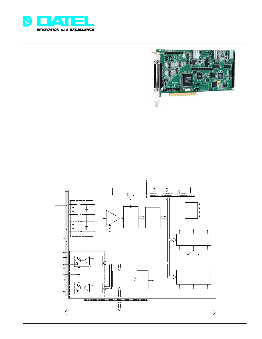
Figure 1. PCI-441 Functional Block Diagram
Using the latest data conversion technology, the PCI-441
combines many of the features usually provided in expensive
stand alone data acquisition systems with significant savings.
Numerous external signal conditioning modules are available
to accommodate various sensor input requirements such as
cold junction compensation (CJC) for thermocouples,
linearization, channel isolation, current inputs, and relay
switching. The PCI bus plug and play (PnP) interface enables
PC auto-detection and initialization, and eliminates all user
hardware configuration. Simply plug the board into your PC,
install DATEL's PCI-441WIN software, and within minutes you
will be analyzing and displaying data in real time, or archiving
that data onto hard disk for later processing.
PCI-441
Precision Sensor Input and Multi-Function
I/O Boards for PCI bus Computers
DATEL, Inc., Mansfield, MA 02048 (USA)
∑
Tel: (508)339-3000, (800)233-2765 Fax: (508)339-6356
∑
Email: sales@datel.com
∑
Internet: www.datel.com
Æ
Æ
Rate Generator Out
PulseRate/Period In
Ext. Event Clock In
External A/D
Trigger In
Analog Inputs
0...15 on PCI-441A/C
0...31 on PCI-441B/D
+10V Out
+5V, 0.75A Fused
4-20 mA Current
Loop Output
DAC V Out 0
Current Loop
Excitation In
DAC V Out 1
4-20 mA Current
Loop Output
M
U
X
2 k
2 k
Signal Conditioning Pad
Software
PGA
PGA Gain
Control
x1, x2, x5, x10
+
≠
16 bit
DAC
4-20 mA Current Loop
+
≠
16 bit
DAC
4-20 mA Current Loop
AMCC S5933
PCI bus
Controller
16-bit
200 kHz
A/D
Converter
512
Sample
FIFO
82C54 Timer
A/D Control
Address
Decode
Logic
Register
Controls
16 Digital
Outputs
16 Digital
Inputs
Data Clock
Input
+5V
Fused 0.75A
End of Conversion
(EOC)
A/D Start Clock
Internal
A/D Clock
External A/D
Clock In
Local Data Bus
PCI Bus
A/D
Clock
A/D
Trigger
A/D Sample
Trigger Count
1 MHz
1 MHz
100 KHz
82C54 Timer
General Purpose
Rate Generator
Event Counter
Period/Frequency Measurement
10 MHz
Ext.
Event
Clock
Control
Signals
EOC
2 k
2 k
R
OPT
C
OPT
R
OPT
C
OPT
Voltage
Reference
and
Temp.
Sensor
+10V
+2.5V
+3.3V
Temp.
Sensor Out
PCI-441B/D
only
PCI-441B/D
only
33
PCI-441
Æ
Æ
DATEL, Inc., Mansfield, MA 02048 (USA)
∑
Tel: (508)339-3000, (800)233-2765 Fax: (508)339-6356
∑
Email: sales@datel.com
∑
Internet: www.datel.com
The PCI-441A or C offers 16 single-ended analog inputs that
are software configurable as 8 true differential inputs.
PCI-441B or D models include an additional 16 single-ended
or 8 differential A/D channels, bringing the total count to 32
single-ended or 16 differential analog inputs. The full scale
input voltage range is ±5V for models PCI-441A and B or ±10V
for the PCI-441C or D. Each input channel includes blank
component pads that are user-configurable to accept different
input voltage ranges, current inputs, simple filters, or other
signal conditioning. A software programmable gain amplifier
(PGA) offers high input signal gains that allow the board to
detect low level sensor inputs. The A/D resolution is 16 bits,
and it can sample at up to 200 thousand times per second.
Channels can be individually sampled, or a software
selectable group of adjacent channels can be scanned
continuously.
A/D data passes directly to an on-board first-in-first-out (FIFO)
memory. This architecture allows non-stop, continuous data
streaming to the PC without losing any samples. PC streaming
mode uses high speed PCI bus mastering (also known as
Direct Memory Access - DMA) to place the data directly into
host memory without CPU intervention. This frees up host
CPU processing time, allowing it to perform other concurrent
tasks such as data analysis, data display, and process control.
Slower speed applications can use the FIFO to store up to 512
samples. Synchronization provided by software detectable
FIFO flags (full, half full, and empty), and an end of trigger
frame indicator, enable the host to periodically read one or all
stored samples, and then return to other simultaneous tasks
until more data is ready.
The A/D sampling rate is software selectable using an on-
board 82C54 timer. The timer allows software programmable
sampling rates from the maximum A/D speed of 200 KHz all
the way down to 15.25 Hz. A/D sampling can also be directly
controlled by a user-supplied external clock input. An internal
programmable trigger timer allows acquisition of blocks of
samples separated by programmable delays. In addition,
external digital triggers can be used. For application
synchronization and event detection, a programmable sample
counter specifies the number of samples per trigger frame,
which is independent of FIFO size and PCI bus transfer
counts. This flexible timing architecture makes the PCI-441 an
ideal solution for most medium speed electronic test,
measurement, instrumentation, and control applications.
A second programmable counter/timer accommodates pulse
rate (frequency) and period measurements, event counting,
clock and timebase generation, square wave generation, and
other general timing applications. An on-board, precision 10
MHz oscillator is used as the timebase for timing and wave
generation. Digital pulse trains can be generated at pre-
programmed rates and software selectable pulse widths for
logic testing and simulation. Externally supplied inputs allow
period and frequency measurements, as well as event
counting.
The PCI-441 provides voltage and current excitation outputs for
RTD's and strain gauges. The strain gauge voltage output is a
regulated +10V (100 mA max.) source, while the RTD current
source output is fixed at 500µA (±2% nominal). To verify strain
gauge voltages and RTD currents these excitation outputs can
be steered by software to the analog inputs. Other on-board
software selectable A/D input sources include 2.5V and 3.33V
fixed references and both D/A channels (on PCI-441B/D only).
An on-board temperature transducer uses a precision bandgap
voltage reference to provide an output voltage that varies
linearly with temperature. This temperature sensor can be
selected as an A/D input for reference temperature
compensation for thermocouples and RTD's.
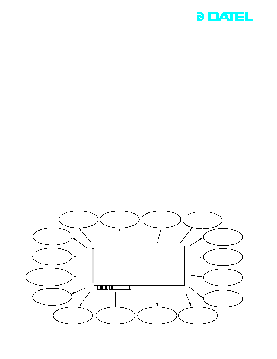
Figure 2. PCI-441 Typical Applications
PCI-441
Multifunction I/O Board
Automotive
Testing
Process
Monitoring and
Control
Temperature and
Pressure Sensing
Automated
Test Equipment
Voice
Recording/
Analysis
Acoustics
Current
Monitors
Intelligent
Control
Stimulus/
Response
Testing
Vibration and
Torque Testing
Transducer
Testing
Accelerometers
Fault
Diagnostics
Laboratory R&D
Simulation
Position/motion
Control
Data Logging
34
PCI-441
Æ
Æ
DATEL, Inc., Mansfield, MA 02048 (USA)
∑
Tel: (508)339-3000, (800)233-2765 Fax: (508)339-6356
∑
Email: sales@datel.com
∑
Internet: www.datel.com
PCI-441WIN(S) Software
Windows
Æ
95/98/NT/2K have become the platforms of choice for
many data acquisition, test, measurement, and control
applications. These feature-rich, 32-bit operating systems exploit
huge gigabyte memory, secure multi-threading, and hardware
plug-and-play (PnP) to provide high performing, user friendly
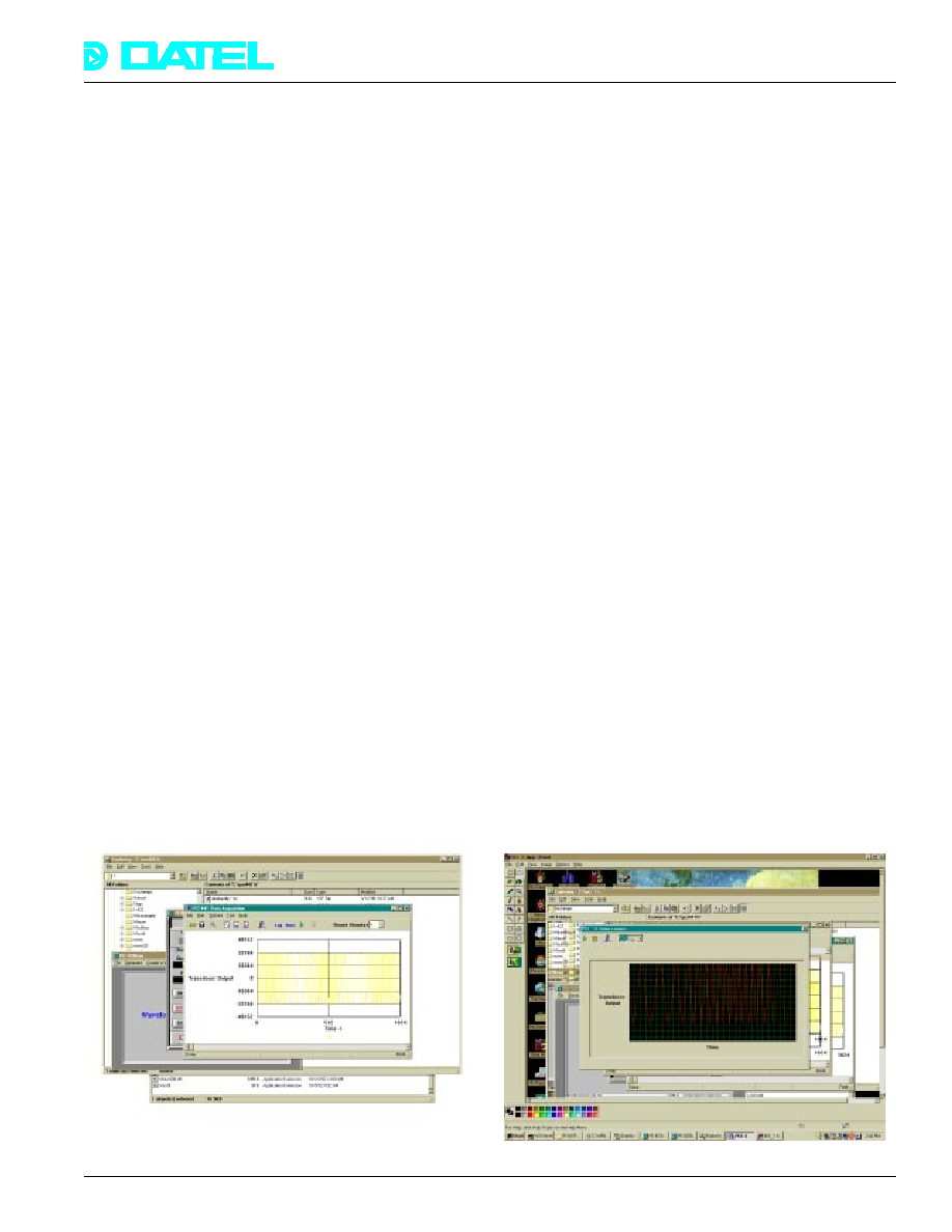
working environments. PCI-441WIN is an interactive data
acquisition, analysis, display, signal generation, and digital I/O
software system for the PCI-441 that runs under Windows
Æ
95/
98/NT/2K. It consists of a point-and-click graphic user interface
(GUI), a dynamic link library (DLL), and a device driver.
PCI-441WIN main features include:
∑
Plug and Play (PnP) hardware detection and initialization.
∑
Easy-to-use, point and click graphic user interface (GUI).
∑
Transparent A/D data transfer to PC memory using DMA.
∑
Control multiple PCI-441's in the same PC simultaneously.
∑
A/D configuration ≠ PGA gain, sample rate, etc.
∑
Set the DAC voltage and 4-20 mA current outputs.
∑
Read and write the digital I/O ports.
∑
Event counting, period, and frequency measurements.
∑
Generate digital signals, program pulse rates and widths.
PCI-441WIN automatically detects the PCI-441, configures the
hardware, and continuously streams A/D sensor data to host
memory using PCI bus DMA. A/D selections such as single-
ended/differential, PGA gain, sample rate, trigger rate, and
channel scan groups can be selected with the mouse.
Generate dynamic voltage waveforms or DC levels from both
DAC voltage and 4-20 mA outputs. Read and write the digital
I/O ports on command, or transfer blocks of data to and from
the ports for pattern recognition, digital signature generation,
and control. Timer control and manipulation selections perform
event counting, pulse rate measurement, and pulse
generation. Skillful graphic manipulation allows display
panning and zooming, and the raw data can be displayed in
decimal or hex, with real time scrolling.
PCI-441WIN turns your PC into an intelligent data logger,
archiving all A/D sensor data to disk for later analysis using
third party applications such as Excel
Æ
, DaDisp
Æ
, LabVIEW
Æ
,
and HyperSignal
Æ
. Analog and digital channel expansion can
be achieved by running multiple PCI-441's in the same PC
simultaneously. Multiple, concurrent real time displays can be
viewed, and the data from each board can be logged to
separate disk files for later analysis.
PCI-441B/D models include two 16-bit digital to analog
converters (DAC's) that add precision adjustable voltage and
current outputs for transducer excitation, process control, and
programmable voltage sources. The full scale output voltage
range is ±10V, at 5 mA maximum per channel. Each DAC
channel drives an on-board 4-20 mA current loop. The
excitation power for the current loop is user-selectable from an
internal 12V reference or from an external 12V to 30V supply.
User supplied excitation allows higher impedance loads to be
connected while still maintaining current loop voltage
compliance. Gain and offset adjustment potentiometers are
provided on each DAC channel for precision calibration. Under
software control, the DAC outputs can drive the analog inputs
for A/D and PGA calibration.
PCI-441B/D models also provide 16 digital inputs and 16
digital outputs for discrete monitoring and control systems,
inter-machine communication, digital pattern recognition,
digital signature generation, and relay switching applications.
All the lines are TTL and CMOS compatible. The output port
latches the data when commanded by host software. A user-
supplied strobe latches data at the input port for reading by
host software. The digital lines are accessed via an internal flat
cable header, that also supplies +5V and ground for external
circuits. Various transition panels allow direct connection to
industry standard interfaces such as Opto 22 modules.
The PCI-441 is built on a three quarter length desktop PCI
board that occupies one PCI slot. The product is manufactured
in DATEL's ISO9001 facility. The PCI bus interface is
implemented using an AMCC S5933 PCI bus controller that
supports full PCI bus mastering.
Figure 3. PCI-441WIN
Figure 4. Strip Chart Recorder/Data Logger
35
PCI-441
Æ
Æ
DATEL, Inc., Mansfield, MA 02048 (USA)
∑
Tel: (508)339-3000, (800)233-2765 Fax: (508)339-6356
∑
Email: sales@datel.com
∑
Internet: www.datel.com
Software engineers and programmers will be interested in
PCI-441WINS -- the source code for PCI-441WIN. It includes
complete source code for the GUI (Borland C
++
Builder) and
the DLL (Visual C
++
5.0), and allows you to communicate with
the PCI-441 from the familiar environment of your favorite high
level language ≠ C, Pascal, Visual
Æ
BASIC, Delphi
Æ
, etc. It's
standard Windows programming hierarchy facilitates custom
software development and PCI-441 integration into other
applications. The source code contains a simple example
console program, written in C, that exercises the PCI-441
through DLL function calls. This illustrates software writing if
you do not normally use Borland's C
++
Builder for GUI
development.
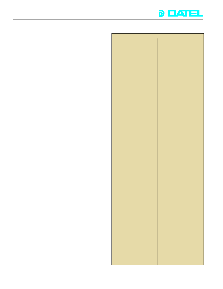
PCI-441WINS hardware register access includes:
Command Register
Control fields for A/D trigger/clock selections, channel
sequencing, single-ended or differential input configuration,
PGA gain selections, and A/D calibration.
Status Register
FIFO flags (empty, half full, and full), counter/timer status, and
channel block scan complete.
Start Channel Register
Select the first A/D channel in a contiguous, sequential group
to scan.
Final Channel Register
Select the last A/D channel in a contiguous, sequential group
to scan.
Reset FIFO
Flush all FIFO data. All previous data not saved will be lost.
A/D Data Register
Read blocks of A/D data.
Interrupt Source / 82C54 Timer Control Register
Select counter/time mode (rate generator, event counter,
period, or frequency measurement), and non-DMA host
interrupt mode (FIFO full, half full, empty, end of trigger block).
Digital Output Register
Write to the 16-bit digital port.
Digital Input Register
Read from the 16-bit digital input port.
Write DAC 0 Register
Update the 16-bit analog output (channel 0).
Write DAC 1 Register
Update the 16-bit analog output (channel 1).
Timer Control Registers
Configure both 82C54 timers.
Timer Data Registers
Load 82C54 timer data.
PCI Control Registers
Read/write access to all the registers on the AMCC S5933 PCI
bus controller.
The hardware user manual contains detailed information on each
bit in all the PCI-441 registers. In addition, it includes the
complete product data book for the AMCC S5933 PCI controller.
*For example, the sample rate per channel sampling 16
channels is 50 KHz/16 = 3.1 KHz/channel.
SPECIFICATIONS
(Typical @ +25∞C, dynamic conditions, gain = 1, unless noted)
ANALOG INPUTS
Number of Input Channels
16 single-ended or 8
differential (PCI-441A or C).
32 single-ended or 16
differential (PCI-441B or D).
Input Configuration
Non-isolated.
Standard Input Voltage Range
±5 V, ±2.5V, ±1V, and ±0.5V
using the software PGA
(models PCI-441A or B)
±10V, ±5V, ±2V, ±1V models
PCI-441C or D. Per-channel
higher ranges are possible by
installing attenuation resistors
in the blank component pads.
A/D Resolution
16 bits.
Single Channel Sample Rate
200 KHz (single channel).
Multi-channel Sample Rate
50 KHz aggregate (per
channel sample rate =
50 KHz/no. of chans.).*
A/D Output Data Coding
Two's complement, sign
extended to indicate polarity.
Programmable Gain
Software programmable --
x1, x2, x5 or x10.
Input Impedance
10M
, minimum.
Signal Conditioning
The board includes
unpopulated component pads
on each channel for user-
installation of current shunts,
attenuators, simple filters, etc.
Common Mode Voltage Range
±10 Volts
Common Mode Rejection
92 dB typical, DC to 60 Hz,
1 K
unbalance, gain=1.
Input Over-voltage
±12 Volts max., sustained no
damage, power on or off.
Diode clamp protection only.
A/D Adjustments
Gain and offset.
Addressing Modes
1. Single channel by random
addressing in software.
2. Short cycle addressing ≠
continuously sample a block
of adjacent channels
Integral Linearity (gain=1)
±4 LSB of full scale range.
Differential Linearity (gain=1)
±3 LSB of full scale range.
Full Scale Temp. Coefficient
±1 LSB per degree C.
Offset/Zero Temp. Coefficient
±1 LSB per degree C.
Total Harmonic Distortion
-80 dB (optimized 16K FFT,
2
nd
to 5
th
harmonics)
Analog Input Connector
Industry standard 37 pin DB-37
female for single-ended
channels 0 through 15
(differential channels 0 through
7). 40 pin internal flat cable
header for single-ended
channels 16 through 31
(differential channels 8 through
15, available on PCI-441B or D
models only.) External
adapter cable available.
36
PCI-441
Æ
Æ
DATEL, Inc., Mansfield, MA 02048 (USA)
∑
Tel: (508)339-3000, (800)233-2765 Fax: (508)339-6356
∑
Email: sales@datel.com
∑
Internet: www.datel.com
ANALOG OUTPUTS (PCI-441B or D only)
Number of D/A Channels
Two, non-isolated
D/A Resolution
16 bits
Settling Time
Full Scale Step
10 µs (100 KHz) max.
Single Step
6 µs
Slew Rate
10V/µs.
Output Voltage Range
±10V per channel.
Output Current
(Voltage outputs)
±5 mA minimum per channel.
Output Impedance
0.1 Ohms.
Short Circuit Protection
Short circuit to ground.
Integral Linearity Error
±4 LSB's maximum.
Differential Linearity Error
±4 LSB's maximum.
D/A Calibration
Gain and offset adjust
potentiometers per channel.
Data Coding
2's complement binary
A/D Excitation
The D/A channels may be
software selected for voltage
excitation of the A/D channels
Current Loop Outputs
Each D/A channel drives a
4-20 mA active current loop.
Current Loop Excitation
Internal fixed +12V supply or
external user-supplied
excitation (12V to 30V).
Current Loop Compliance
12V to 30V, non-isolated.
RTD Current Excitation
RTD excitation is fixed at
500 µA, ±2% typical. Under
software control the PCI-441
can verify that the RTD
current is present by directing
this excitation output to the
A/D.
Strain Gauge Excitation
10V regulated, ±2%, 100 mA
max. current output. Under
software control the PCI-441
can verify that strain gauge
voltage is present by directing
this reference output to the A/D.
Temperature Transducer
On-board bandgap voltage
source that varies linearly
with temperature. It has an
output voltage of 590 mV at
25∞C, and a temperature
coefficient of 2mV per ∞C.
A/D Sample Clock (82C54)
Internal software
programmable or external
TTL input.
A/D Frame Trigger
Internal software
programmable or external
TTL input.
A/D Sample Counter
Software programmable to
65535 samples. Can disable
in software for continuous,
non-stop sampling for long
periods.
A/D FIFO Memory
512 A/D samples
SENSOR EXCITATION OUTPUTS (all models)
A/D TIMING AND FIFO MEMORY
GENERAL PURPOSE COUNTER/TIMER
Input Functions
Pulse rate and period
measurement, and event
counting.
Output Functions
Clock, timebase, or square
wave generator.
Clock source
Internal 10 MHz crystal or
external input (10 MHz max.).
Gate source
Internal (software) or external.
Input/output levels
1 TTL load min. (output),
1 TTL-LS load max. (input).
Controller
Standard 82C54 timer.
Number of channels
16 inputs and 16 outputs.
Logic Levels
TTL-CMOS compatible.
Input Voltage
Input LOW Voltage 0.8V max.
Input HIGH Voltage 2.2V min.
Input Leakage Current
10 milliamps.
Output Voltage
Output HIGH 3.8 V min.
Output LOW 0.5 V max.
Output Drive Current
Output High or Low 24 mA.
Connector
50 pin internal flat cable
header, external adapter
cable available
Throughput
2 MHz
Operating Temp. Range
0 to +60∞C
Storage Temperature Range
-25 to +85∞C no thermal shock.
Relative Humidity
10% to 90%, non-condensing.
Altitude
0 to 10,000 feet. Forced
cooling is required.
Warm-Up Period
5 minutes to rated accuracy.
Bus Interface
32-bit desktop PCI bus using
the AMCC S5933 controller.
PCI Bus Mastering
PCI bus mastering (DMA) is
automatically included with
the AMCC S5933.
PCI Interrupt Sources
Non-DMA mode: A/D FIFO
full, FIFO half full, FIFO empty,
and end of trigger frame/block.
DMA Mode: DMA T/C
Local RAM
The board includes non-
volatile Random Access
Memory (NVRAM) to initialize
the PCI controller, store
calibration tables, and other
model specific information.
Mechanical Outline
æ length desktop PCI bus
Dimensions
board ≠ 24cm x 9.9cm x
1.0cm. Occupies one PCI slot.
Regulated DC Power
Required
Supplied by the host PCI bus:
+5Vdc @ 750mA max.,
500 mA typical
+12Vdc @ 250mA max.,
150 mA typical
-12Vdc @ 150mA max.,
100 mA typical
Manufacturing Environment
ISO 9001 certified facility.
DIGITAL INPUT/OUTPUT PORT (PCI-441B or D only)
MISCELLANEOUS
ENVIRONMENTAL
37

PCI-441
Æ
Æ
DATEL, Inc., Mansfield, MA 02048 (USA)
∑
Tel: (508)339-3000, (800)233-2765 Fax: (508)339-6356
∑
Email: sales@datel.com
∑
Internet: www.datel.com
PCI-441LV for LabVIEW
Æ
(Windows
Æ
95/98/NT/2K only)
Virtual instrumentation has revolutionized data acquisition and
process control. LabVIEW
Æ
from National Instruments pioneers
virtual instrumentation. Save yourself weeks and months of
software development by graphically assembling your
programs as a block diagrams rather than writing code.
Together with Datel's PCI-441LV driver library, LabVIEW
Æ
transforms the PCI-441 into easy-to-use virtual instruments
that acquire, analyze, display, and archive digitized waveforms
in real time, use the timer I/O for event counting and rate
generation and measurement, and use the digital I/O and D/A
channels for process control. Low level software development
is replaced by visual, drag-and-drop programming that
harnesses all the power of Windows
Æ
95/98/NT/2K ≠ graphic
user interface (GUI), huge gigabyte memory, multi-tasking,
plug-and-play, and inter-process communication via OLE/DDE.
How does PCI-441 programming under LabVIEW
Æ
work? It's
very simple! Using the mouse, you select a set of VI's from a
function palette and "wire" them together...like creating a
flowchart. There is absolutely no coding involved. All the low-
level hardware interaction and control is transparently included
in the drag-and-drop VI's supplied in PCI-441LV. You can
concentrate on the real specifics of your application (such as
data processing, display, and storage), rather than wasting
time getting the hardware up and running. In addition to the
hardware control provided by PCI-441LV, LabVIEW
Æ
provides
hundreds of data analysis and display functions that can be
used in real time or for post-processing.
PCI-441LV is a comprehensive library of simple, fast, modular VI's
that allow complete hardware control. VI's can be visually strung
together to acquire non-stop, seamless data into huge host
buffers using PCI DMA or CPU status polling. Multiple PCI-441's
can be configured to operate simultaneously in the same PC. You
can install and run as many boards as there are vacant PCI bus
slots in your computer. All boards will perform concurrent PCI bus
DMA data transfer to host memory without conflicts.
Datel's VI library includes complete functional VI programs that
exercise all PCI-441 features ≠ A/D, D/A, digital I/O, event
counting, rate generation, and period/frequency
measurements. They include:
∑ Plug-and-play hardware detection and initialization.
∑ Run multiple PCI-441's in the same PC.
∑ Allocate DMA buffers ≠ single and dual (circular buffering).
∑ Configure data acquisition ≠ sample and trigger rate, clock/
trigger source, sample count, channel scan blocks, etc.
Figure 5. PCI-441LV Virtual Instrument
∑ Update analog outputs ≠ voltage and 4-20mA current.
∑ Read and write the digital I/O ports.
∑ Configure the event counter and rate generator.
∑ Measure pulse frequency and period.
∑ Monitor the FIFO flags during data acquisition.
∑ Transfer data from the FIFO using status or PCI bus DMA.
∑ Pause DMA ≠ allow access to local registers during DMA.
∑ Reload the DMA registers without interrupting the A/D.
∑ Low level register I/O ≠ read/write all PCI-441 registers.
∑ Fully functional VI example programs to illustrate usage.
The LabVIEW
Æ
libraries, supplied by National Instruments,
include hundreds of user-interaction, data analysis, and data
display functions, including:
Controls/indicators
Meters/gauges
Knobs/dials
Toggle/slide switches
Slider controls
Numeric math
Boolean evaluation
Looping
Histograms
Standard deviation
Matrix math
Vector Math
Linear evaluation
Polynomials
Statistics
Curve fitting
File I/O
2-D plotting
3-D plotting
Charts/graphs
Frames/borders
Internet communication
OLE automation DDE
In addition, National Instrument's offers various add-on and
helper packages for LabVIEW
Æ
. An Advanced Analysis package
provides still more data analysis and display functions. The DSP
Analysis library includes signal generation functions (impulse,
pattern, white noise, etc.), various digital filters, data windowing,
and time and frequency domain processing. Application Builder
Æ
can be used to generate a standalone application from your VI
program. This can then be executed under Windows
Æ
95/98/NT/
2K, independent of LabVIEW
Æ
. Make your applications Internet-
aware with the Internet Developers Toolkit
Æ
. Transfer data via E-
mail or FTP and use a Web browser to monitor and control
experiments remotely on the World Wide Web. Please contact
National Instruments directly for more information on these and
other "plug-ins".
PCI-441LV is accompanied by a detailed user manual that
describes each VI. LabVIEW
Æ
allows DLL function calls directly
from a VI graphic. If you wish to develop your own VI's or
modify existing VI's, PCI-441LVS is the source code for PCI-
441LV. It includes all functions contained in the dynamic link
library(DLL). The DLL, which was developed using Microsoft
Visual C
++
5.0, implements all hardware control and monitor
functions and does not need to be modified. To help with your
development, the DLL functions are thoroughly documented in
the PCI-441 users manual.
Figure 6. PCI-441LV Visual Program
38
PCI-441
Æ
Æ
DATEL, Inc., Mansfield, MA 02048 (USA)
∑
Tel: (508)339-3000, (800)233-2765 Fax: (508)339-6356
∑
Email: sales@datel.com
∑
Internet: www.datel.com
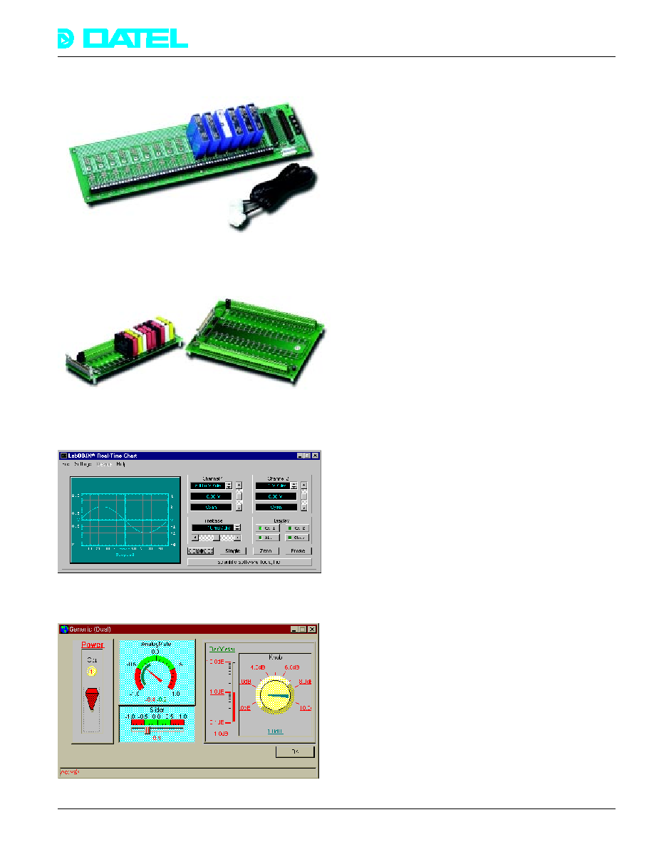
PC-5B Series Modules
The 5B Series provides excellent signal conditioning performance.
Modules can be mixed and matched on one backplane, permitting
users to address their exact needs, and may be changed without
disturbing field wiring. The isolated input modules provide 0 to +5
V, or ≠5 V to +5 V outputs (depending on model type) and accept J,
K, T, E, R, S, N, and B thermocouples; 100
platinum RTD's;
strain gauges; mV, V, 4-20 mA, frequency (0 to 250 KHz), and wide
bandwidth (10 KHz) mV and V signals. These modules feature
complete signal conditioning functions including CJC (Cold
Junction Compensation) for Thermocouple inputs.
Solid State Relays
DATEL offers the industry standard G4 series of base boards,
solid state and mechanical relay modules, as well as some
custom designed mechanical relay boards and screw terminal
panels. Direct connect cabling is also available.
RT Chart
LabOBJX Real-Time Chart is a versatile 32-bit Active-X control for
quickly and easily adding high-speed graphing and charting to your
data acquisition applications. LabOBJX Real-Time Chart uses
advanced graphical techniques to maximize visual display rates for
creating realistic and fast oscilloscope and strip chart displays.
VIX COMponents
VIX COMponents is a collection of Active X controls and
functions for data analysis, manipulation, and control. You can
create professional looking data acquisition and control
applications by dropping one or more Active X controls like
analog meter, strip chart, switches, knobs, and more onto your
form.
39
PCI-441
Æ
Æ
DATEL, Inc., Mansfield, MA 02048 (USA)
∑
Tel: (508)339-3000, (800)233-2765 Fax: (508)339-6356
∑
Email: sales@datel.com
∑
Internet: www.datel.com
ORDERING INFORMATION
PCI-441A
Multifunction PCI board with 16S/8D A/D inputs, ±5V full scale range. Includes timer I/O and PCI-441WIN
(binary executables only) for Windows
Æ
95/98/NT/2K. No D/A's or digital I/O.
PCI-441B
Same as PCI-441A with the addition of 16S/8D analog outputs (total 32S/16D), two D/A's with 4 - 20 mA
current loops and digital I/O.
PCI-441C
Multifunction PCI board with 16S/8D A/D inputs, ±10V full scale range. Includes timer I/O and PCI-441WIN
(binary executables only) for Windows
Æ
95/98/NT/2K. No D/A's or digital I/O.
PCI-441D
Same as PCI-441C with the addition of 16S/8D analog inputs (total 32S/16D), two D/A's with 4 - 20 mA
current loops and digital I/O.
PCI-441WIN
Windows
Æ
95/98/NT/2K software application included with PCI-441. Interactive data acquisition that includes
data analysis, display, signal generation, and digital I/O control features. It includes a Windows device driver,
DLL, and graphic user interface (GUI).
PCI-441WINS
Source code for PCI-441WIN. Includes the source code for the GUI, (written using Borland's C
++
Builder
Æ
), and
the DLL source code (written using Microsoft Visual C
++
5.0
Æ
). Includes a simple console program, (written in
Microsoft C), that illustrates DLL function calling without the GUI.
PCI-441LV
Library of drivers for National Instruments' LabVIEW
Æ
for Windows
Æ
95/98/NT/2K. Purchase LabVIEW
separately from National Instruments.
PCI-441LVS
Library of LabVIEW
Æ
drivers for Windows
Æ
95/98/NT/2K. Includes DLL source code.
Accessories
Request the DATEL Data Acquisition Accessories data sheet for more information.
All boards are fully burned in, tested, and calibrated at the factory. All boards are shipped with a comprehensive hardware users
manual, which includes register details, timing diagrams, and application information. The manual also contains software
documentation, including API reference manuals for the source code (PCI-441WINS)
VIsit out our Web site at
www.datel.com for Datel's complete product offerings, selection tables, and technical data sheets.
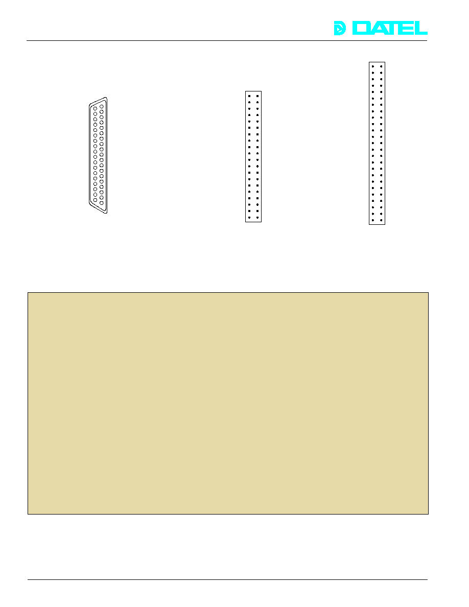
19 Ground
18 Analog In 8/0 Lo
17 Analog In 9/1 Lo
16 Analog In 10/2 Lo
15 Analog In 11/3 Lo
14 Analog In 12/4 Lo
13 Analog In 13/5 Lo
12 Analog In 14/6 Lo
11 Analog In 15/7 Lo
10 4-20 mA Output - Channel 0
9 Analog V Out 0
8 Current Loop Exc. In (+12V
°
+30V)
7 Ground
6 External Trigger In*
5 Gate 1 In
4 Ground
3 Ground
2 Spare (Connected to E11)
1 +5V Bus (Fuse)
Analog In 0 37
Analog In 1 36
Analog In 2 35
Analog In 3 34
Analog In 4 33
Analog In 5 32
Analog In 6 31
Analog In 7 30
Ground 29
Ground 28
Analog V Out 1 27
4-20 mA Output - Channel 1 26
External A/D Clock In 25
Gate 0 In 24
0.5 mA Current Ref. Out 23
10V, 100 mA Excitation Out 22
Timer Clock In 21
Rate Generator Out 20
(Single ended/differential)
Digital In 00 1
2 Digital In 01
Digital In 02 3
4 Digital In 03
Digital In 04 5
6 Digital In 05
Digital In 06 7
8 Digital In 07
Digital In 08 9
10 Digital In 09
Digital In 10 11
12 Digital In 11
Digital In 12 13
14 Digital In 13
Digital In 14 15
16 Digital In 15
Ground 17
18 Input Data Strobe
Ground 19
20 No Connection
Ground 21
22 Ground
Ground 23
24 No Connection
Ground 25
26 Ground
0.75A Fuse +5V Out 27
28 Ground
0.75A Fuse +5V Out 29
30 Ground
Ground 31
32 Ground
No Connection 33
34 Ground
Digital Output 00 35
36 Digital Out 01
Digital Output 02 37
38 Digital Out 03
Digital Output 04 39
40 Digital Out 05
Digital Output 06 41
42 Digital Out 07
Digital Output 08 43
44 Digital Out 09
Digital Output 10 45
46 Digital Out 11
Digital Output 12 47
48 Digital Out 13
Digital Output 14 49
50 Digital Out 15
Figure 7. Rear Panel
Figure 8. Auxilliary Analog Input
Figure 9. Digital I/O
DB-37 Connector (J1)
Connector - P2 (PCI-441B or D only)
Connector - P5 (PCI-441B or D only)
Input/Output Connectors
Pentium is an Intel trademark
Windows and MS-DOS are Microsoft trademarks
Hypersignal is a Hyperception trademark
LabVIEW is a National Instruments trademark
No Connection 1
2 No Connection
No Connection 3
4 No Connection
Ground 5
6 No Connection
Ground 7
8 No Connection
No Connection 9
10 No Connection
No Connection 11
12 No Connection
Ground 13
14 No Connection
No Connection 15
16 No Connection
No Connection 17
18 Ground
No Connection 19
20 Ground
Analog In 31/15 Lo 21
22 Analog In 23/15 Hi
Analog In 30/14 Lo 23
24 Analog In 22/14 Hi
Analog In 29/13 Lo 25
26 Analog In 21/13 Hi
Analog In 28/12 Lo 27
28 Analog In 20/12 Hi
Analog In 27/11 Lo 29
30 Analog In 19/11 Hi
Analog In 26/10 Lo 31
32 Analog In 18/10 Hi
Analog In 25/9 Lo 33
34 Analog In 17/9 Hi
Analog In 24/8 Lo 35
36 Analog In 16/8 Hi
Ground 37
38 No Connection
No Connection 39
40 No Connection
40
Rev. A 3/00


