
INNOVATION and EX C ELL E N C E
Æ
Æ
Single Output
UCP Models
UL/EN Approved, "Half-Brick"
40-75 Watt, DC/DC Converters
Features
The high effi ciency, low noise and long-term reliability that defi nes DATEL
DC/DC Converters now comes to you in the standard "half-brick" confi guration (2.3"
x 2.4" x 0.52"). All models in our new UCP Series meet UL/EN60950 safety require-
ments, including each European country's deviations. A CB Test Certifi cate/Report
is available. All models have BASIC insulation; guarantee 1500Vdc isolation; and
because they are designed with Class B thermal insulation, satisfy all safety require-
ments over their full operating temperatures.
UCP Models are designed for demanding telecom, datacom and networking
applications. Their "semi-synchronous-rectifi er" design (400kHz switching) achieves
impressive effi ciencies (up to 88%). Output voltages are 3.3, 5, 12 or 15 Volts. Input
voltage ranges are 10-18V ("D12" models), 18-36V ("D24" models) or 36-75V ("D48"
models). "D48" models meet the Low Voltage Directive (LVD) and carry the CE mark.
For high reliability and affordability, DATEL utilizes high-speed automatic assem-
bly to construct the UCP's proven SMT-on-pcb designs. All models have been rigor-
ously qualifi ed (including a 500-hour life test) and EMC characterized. Devices are
housed in metal cases (with non-conductive baseplates) that incorporate threaded
inserts for add-on heat sinks and/or pcb mounting.
UCP's feature input pi fi lters, input undervoltage and overvoltage lockout, output
current limiting, short-circuit protection, and thermal shutdown. Additionally, all
devices have output trim capability and an on/off control pin that can be ordered
with either polarity or replaced with a sync function. We can easily modify standard-
product UCP's to meet your application-specifi c requirements.
Figure 1. Simplifi ed Schematic
Standard "half-brick" confi guration
UL/EN60950 safety approvals
(BASIC insulation)
mark for "D48" models
(36-75V inputs)
Fully isolated, 1500Vdc guaranteed
Output voltages: 3.3, 5, 12 or 15 Volts
V
IN
ranges: 10-18V, 18-36V, 36-75V
Full 40-75 Watt output power
Reliable SMT-on-pcb construction
Input under and overvoltage shutdown
Output current limiting and
short-circuit protection
On/off, V
OUT
trim and sense functions
Modifi cations and customs for OEM's
≠V
OUT
+V
IN
≠V
IN
PWM
CONTROLLER
OPTO
ISOLATION
REFERENCE &
ERROR AMP
COMPARATORS
UVLO & OVLO
ON/OFF
CONTROL
TRIM
+SENSE
≠SENSE
+V
OUT
SWITCH
CONTROL
(3)
(1)
(4)
(5)
(6)
(9)
10
10
(8)
(7)
The On/Off Control function can be ordered with either positive (standard) or negative polarity.
It can also be replaced with an optional Sync function.
12V- and 15V-output models have a standard forward architecture in which this FET is replaced
with a Schottky diode.
DATEL, Inc., Mansfi eld, MA 02048 (USA) ∑ Tel: (508)339-3000, (800)233-2765 Fax: (508)339-6356 ∑
Email: sales@datel.com ∑ Internet: www.datel.com
XCP Series
4 0 - 7 5 W , S I N G L E O U T P U T D C / D C C O N V E R T E R S
Output Confi guration:
U = Unipolar
Nominal Output Voltage:
3.3, 5, 12 or 15 Volts
CP
/
Input Voltage Range:
D12 = 10-18 Volts (12V nominal)
D24 = 18-36 Volts (24V nominal)
D48 = 36-75 Volts (48V nominal)
Maximum Output Current
in Amps
Standard Half-Brick Package
5
U
12
-
D48
-
N
See Optional Functions
BOTTOM VIEW
(4) THREADED INSERTS
#M3 THD THRU
1
2
3
4
5
6
7
8
9
1.900
(48.26)
2.000
(50.80)
2.30
(58.42)
0.515
(13.08)
0.20 MIN.
(5.08)
0.20
(5.08)
0.400
(10.16)
0.700
(17.78)
0.50
(12.70)
1.000
(25.40)
1.400
(35.56)
2.40
(60.96
0.20
(5.08)
METAL CASE
PIN DIAMETERS:
PINS 1-4, 6-8
0.040 ±0.002 (1.016 ±0.051)
PINS 5, 9
0.080 ±0.002 (2.032 ±0.051)
INSULATED BASE
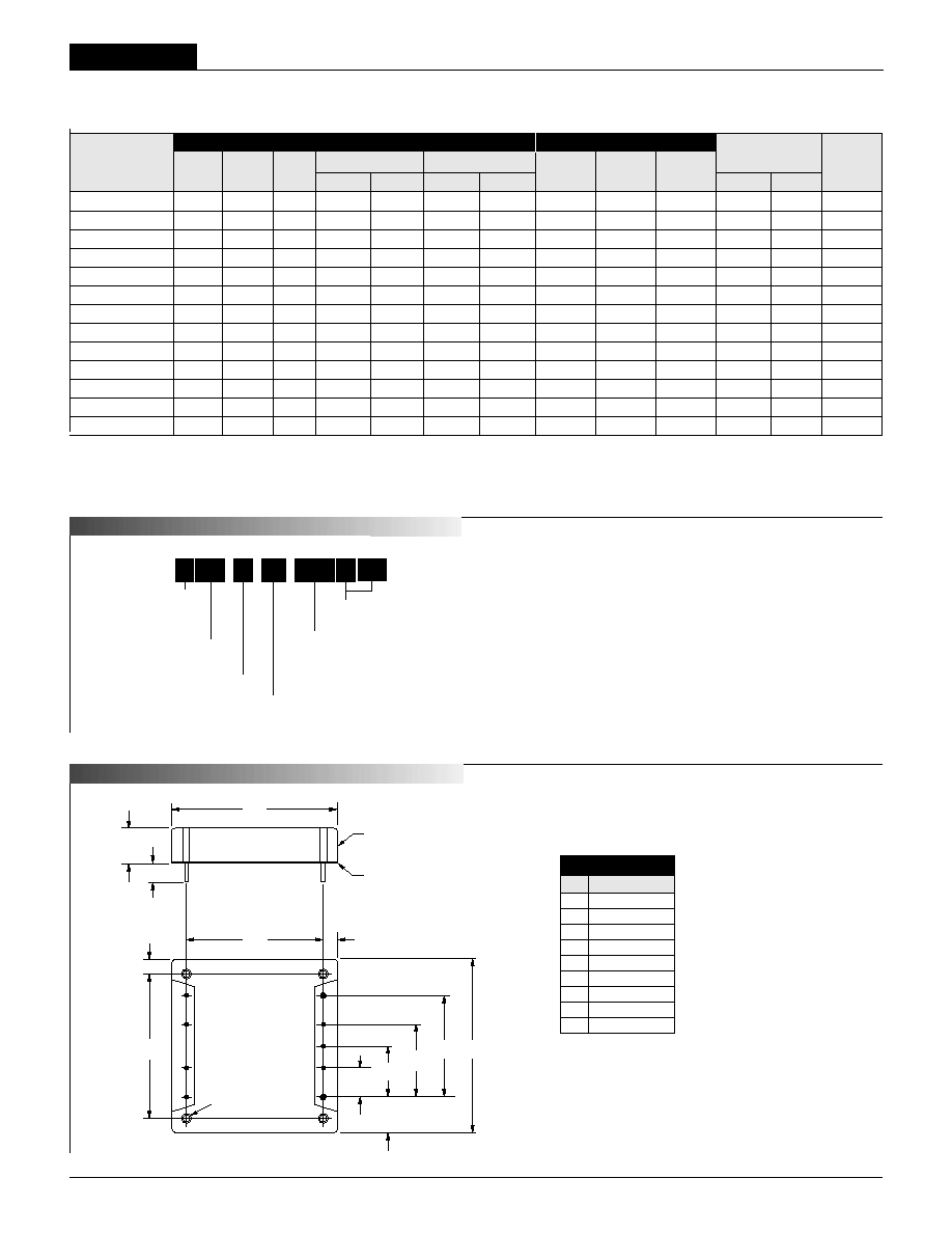
Case C12
Optional Heat Sinks
DATEL offers two heat sinks (part
number HS-CP and HS-CPLP2) for
the UCP models. For mechanical
specifi cations, see page 7.
Typical at T
A
= +25∞C under nominal line voltage and full-load conditions unless otherwise noted.
Ripple/Noise (R/N) measured over a 20MHz bandwidth. All models are specifi ed with external
33µF, low-ESR, input capacitors and 10µF tantalum in parallel with 1µF ceramic output capacitors.
Performance Specifi cations and Ordering Guide
Package
V
OUT
I
OUT
P
OUT
R/N (mVp-p)
Regulation (Max.)
V
IN
Nom. Range I
IN
Effi ciency (Case,
Model (Volts)
(Amps) (W) Typ.
Max. Line
Load
(Volts) (Volts) (mA/A) Min. Typ. Pinout)
UCP-3.3/1
2-D12 3.3 12 40 75 150 ±0.5% ±1.0% 12 10-18 200/4.2 81% 83% C12, P17
UCP-3.3/15-D24 3.3
15 50 75
150 ±0.5% ±1.0% 24 18-36 75/2.6 81%
83% C12, P17
UCP-3.3/15-D48 3.3
15 50 75
150 ±0.5% ±1.0% 48 36-75 75/1.3 81%
83% C12, P17
UCP-5/10-D12 5
10 50 75
120 ±0.5% ±1.0% 12 10-18 200/5.2 82%
84% C12, P17
UCP-5/12-D24 5
12 60 75
120 ±0.5% ±1.0% 24 18-36 75/3 85%
87% C12, P17
UCP-5/12-D48 5
12 60 75
120 ±0.5% ±1.0% 48 36-75 75/1.5 84%
86% C12, P17
UCP-5/15-D48 5
15 75 75
120 ±0.5% ±1.0% 48 36-75 100/1.9 84.5% 86% C12, P17
UCP-12/4.2-D12 12
4.2 50 75
120 ±0.5% ±1.0% 12 10-18 100/5 85%
87% C12, P17
UCP-12/5-D24 12
5 60 75
120 ±0.5% ±1.0% 24 18-36 50/3 84%
86% C12, P17
UCP-12/5-D48 12
5 60 75
120 ±0.5% ±1.0% 48 36-75 50/1.5 86%
88% C12, P17
UCP-15/3.3-D12 15
3.3 50 100
150 ±0.5% ±1.0% 12 10-18 100/4.9 85%
87% C12, P17
UCP-15/4-D24 15
4 60 100
150 ±0.5% ±1.0% 24 18-36 50/2.9 86%
88% C12, P17
UCP-15/4-D48 15
4 60 100
150 ±0.5% ±1.0% 48 36-75 50/1.5 86%
88% C12, P17
Output
Input
LX
10% to 100% load step.
Nominal line voltage, no-load/full-load conditions.
M E C H A N I C A L S P E C I F I C A T I O N S
P A R T N U M B E R S T R U C T U R E
Optional Functions
UCP 40-75 Watt DC/DC's are designed with an On/Off Control
function, with either positive polarity (no suffi x) or negative polarity
("N" suffi x), in the pin 3 position.
Blank On/Off Control function (positive polarity) on pin 3
N On/Off Control function (negative polarity) on pin 3
L1 Pin length: 0.110 inches (2.79mm) ±0.010
L2 Pin length: 0.145 inches (3.68mm) ±0.010
I/O Connections
Pin Function P17
1 ≠Input
2 Case
3 On/Off Control
4 +Intput
5 +Output
6 +Sense
7 Trim
8 ≠Sense
9 ≠Output
2

UCP Models
4 0 - 7 5 W , S I N G L E O U T P U T D C / D C C O N V E R T E R S
Performance/Functional Specifi cations
Typical @ T
A
= +25∞C under nominal line voltage and full-load conditions, unless noted.
Input Voltage:
Continuous:
D12 Models 22 Volts
D24 Models 44 Volts
D48 Models 88 Volts
Transient (100msec):
D12 Models 25 Volts
D24 Models 50 Volts
D48 Models 100 Volts
Input Reverse-Polarity Protection Current must be <15/10 Amps. Brief
duration only. Fusing recommended.
Output Overvoltage Protection
3.3V Outputs 4.5 Volts, limited duration
5V Outputs 6.8 Volts, limited duration
12V Outputs 15 Volts, limited duration
15V Outputs 18 Volts, limited duration
Output Current Current limited. 12/15V devices can
withstand an output short circuit for a
brief duration only. 3.3/5V devices can
withstand output shorts indefi nitely.
Storage Temperature ≠40 to +105∞C
Lead Temperature (soldering, 10 sec.) +300∞C
These are stress ratings. Exposure of devices to any of these conditions may adversely
affect long-term reliability. Proper operation under conditions other than those listed in the
Performance/Functional Specifi cations Table is not implied.
Absolute Maximum Ratings
Input
Input Voltage Range:
D12 Models 12-18 Volts (12V nominal)
D24 Models 18-36 Volts (24V nominal)
D48 Models 36-75 Volts (48V nominal)
Overvoltage Shutdown:
D12 Models 20 Volts
D24 Models 40 Volts
D48 Models 80 Volts
Start-Up Threshold:
D12 Models 9.5 Volts
D24 Models 17 Volts
D48 Models 35 Volts
Undervoltage Shutdown:
D12 Models 9 Volts
D24 Models 16 Volts
D48 Models 34 Volts
Input Current:
Normal Operating Conditions See Ordering Guide
Standby Mode (Off, OV, UV) 5mA
Input Filter Type Pi
Reverse-Polarity Protection:
D12/D24 Models Brief duration, 15A maximum
D48 Models Brief duration, 10A maximum
On/Off Control (Pin 3)
TTL high (or open) = on, low = off
Output
V
OUT
Accuracy (50% load):
3.3V Outputs ±1.5%, maximum
5/12/15V Outputs ±1%, maximum
Temperature Coeffi cient ±0.04% per ∞C
Ripple/Noise (20MHz BW)
See Ordering Guide
Line/Load Regulation See Ordering Guide
Effi ciency See Ordering Guide
Isolation Voltage:
Input-to-Output 1500Vdc, minimum
Input-to-Case 1500Vdc, minimum
Output-to-Case 1500Vdc, minimum
Isolation Capacitance 750pF
Isolation Resistance 100M
Current Limiting:
3.3V and 5V Outputs Hiccup technique, auto-recovery
12V and 15V Outputs Power-limiting technique, auto-recovery
Overvoltage Protection Zener/transorb clamp, magnetic feedback
Dynamic Characteristics
Transient Response (50% load step) 200µsec max. to ±1.5% of fi nal value
Start-Up Time:
V
IN
to V
OUT
50msec
On/Off to V
OUT
30msec
Switching Frequency 400kHz (±25kHz)
Environmental
Operating Temperature (Ambient):
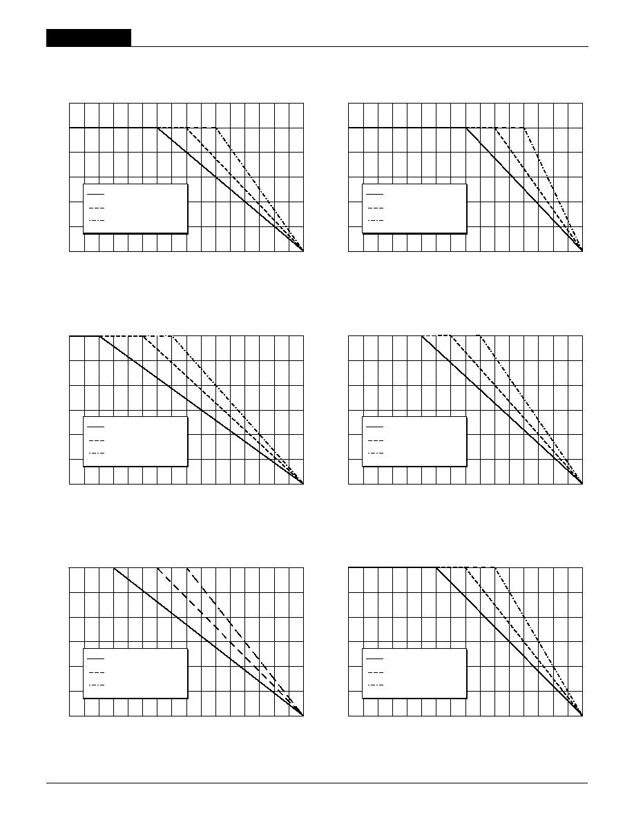
Without Derating ≠40 to +45/50∞C (Model dependent)
With Derating to +100∞C (See Derating Curves)
Case Temperature:
Maximum Allowable +100∞C
For Thermal Shutdown +95∞C minimum, +105∞C maximum
Storage Temperature ≠40 to +105∞C
These power converters require a minimum 10% output loading to maintain specifi ed
regulation. Operation under no-load conditions will not damage these devices; however
they may not meet all listed specifi cations.
All models are specifi ed with external 33µF, low-ESR, input capacitors and 10µF tantalum
in parallel with 1µF ceramic output capacitors.
See Technical Notes for details.
Devices may be ordered with the opposite polarity (pin 3 open = off), or the on/off control
function can be replaced with a sync function. See Part Number Suffi xes and Technical
Notes for additional information.
Accracy is specifi ed with the sense pins tied directly to their respective output pins.
Output noise may be further reduced with the installation of additional external output
capacitors. See Technical Notes.
Physical
Dimensions 2.3 x 2.4 x 0.515" (58.4 x 61 x 13.1mm)
Shielding 5-sided
Case Connection Pin 2
Case Material Zinc with a non-conductive, epoxy-based
black enamel fi nish and plastic baseplate
Pin Material Brass, solder coated
Weight 5.3 ounces (149 grams)
3
XCP Series
4 0 - 7 5 W , S I N G L E O U T P U T D C / D C C O N V E R T E R S
4
D12 Models (50 Watts)
Figure 2a. Temperature Derating Without Heat Sink
Figure 2b. Temperature Derating With HS-CP Heat Sink
Figure 3a. Temperature Derating Without HS-CP Heat Sink
Figure 3b. Temperature Derating With HS-CP Heat Sink
D24 Models (60 Watts)
Out
put Powe
r
(
W
atts
)
Ambient Temperature (∞C)
60
50
40
30
20
10
0
Natural Convection Cooling
150 Linear Feet Per Minute
300 Linear Feet Per Minute
≠40 0 30 35 40
45 50 55 60 65 70 75 80 85 90
95 100
Out
put Powe
r
(
W
atts
)
Ambient Temperature (∞C)
60
50
40
30
20
10
0
Natural Convection Cooling
150 Linear Feet Per Minute
300 Linear Feet Per Minute
≠40 0 30 35 40
45 50 55 60 65 70 75 80 85 90
95 100
Out
put Powe
r
(
W
atts
)
Ambient Temperature (∞C)
60
50
40
30
20
10
0
Natural Convection Cooling
150 Linear Feet Per Minute
300 Linear Feet Per Minute
≠40 0 30 35 40
45 50 55 60 65 70 75 80 85 90
95 100
Out
put Powe
r
(
W
atts
)
Ambient Temperature (∞C)
60
50
40
30
20
10
0
Natural Convection Cooling
150 Linear Feet Per Minute
300 Linear Feet Per Minute
≠40 0 30 35 40
45 50 55 60 65 70 75 80 85 90
95 100
Out
put Powe
r
(
W
atts
)
Ambient Temperature (∞C)
60
50
40
30
20
10
0
Natural Convection Cooling
150 Linear Feet Per Minute
300 Linear Feet Per Minute
≠40 0 30 35 40
45 50 55 60 65 70 75 80 85 90
95 100
Out
put Powe
r
(
W
atts
)
Ambient Temperature (∞C)
60
50
40
30
20
10
0
Natural Convection Cooling
150 Linear Feet Per Minute
300 Linear Feet Per Minute
≠40 0 30 35 40
45 50 55 60 65 70 75 80 85 90
95 100
Figure 4a. Temperature Derating Without HS-CP Heat Sink
Figure 4b. Temperature Derating With HS-CP Heat Sink
D48 Models (60 Watts)
UCP Models
4 0 - 7 5 W , S I N G L E O U T P U T D C / D C C O N V E R T E R S
5
Floating Outputs
Since these are isolated DC/DC converters, their outputs are "fl oating."
Designers will usually use the ≠Output (pin 9) as the ground/return of the
load circuit. You can, however, use the +Output (pin 5) as ground/return to
effectively reverse the output polarity.
Filtering and Noise Reduction
All UCP DC/DC Converters achieve their rated ripple and noise specifi cations
using the external input and output capacitors specifi ed in the Performance/
Functional Specifi cations table. In critical applications, input/output noise may
be further reduced by installing additional external I/O caps. Input capacitors
should be selected for bulk capacitance, low ESR and high rms-ripple-current
ratings. Output capacitors should be selected for low ESR and appropriate
frequency response. All caps should have appropriate voltage ratings and be
mounted as close to the converters as possible.
The most effective combination of external I/O capacitors will be a function
of your particular load and layout conditions. Our Applications Engineers will
be happy to recommend potential solutions and can discuss the possibility of
our modifying a given device's internal fi ltering to meet your specifi c require-
ments. Contact our Applications Engineering Group for additional details.
Input Fusing
Certain applications and/or safety agencies may require the installation of
fuses at the inputs of power conversion components. Fuses should also be
used if the possibility of sustained, non-current-limited, input-voltage polarity
reversals exists. For DATEL UCP DC/DC Converters, you should use slow-
blow type fuses with values no greater than the following.
V
IN
Range Fuse Value
D12 Models 7 Amps
D24 Models 6 Amps
D48 Models 3 Amps
Start-Up Threshold and Undervoltage Shutdown
Under normal start-up conditions, devices will not begin to regulate until
the ramping-up input voltage exceeds the Start-Up Threshold Voltage (35V
for "D48" models). Once operating, devices will not turn off until the input
voltage drops below the Undervoltage Shutdown/Lockout limit (34V for "D48"
models). Subsequent re-start will not occur until the input is brought back
up to the Start-Up Threshold. This built-in hysteresis obviously avoids any
unstable on/off situations at a single voltage.
Start-Up Time
The V
IN
to V
OUT
start-up time is the interval between the time at which
a ramping input voltage crosses the turn-on threshold point and the fully-
loaded output voltage enters and remains within its specifi ed accuracy band.
Actual measured times will vary with input source impedance, external input
capacitance, and the slew rate and fi nal value of the input voltage as it
appears to the converter.
The On/Off to V
OUT
start-up time assumes the converter has its nominal input
voltage applied but is turned off via the On/Off Control. The specifi cation
defi nes the interval between the time at which the converter is turned on
and the fully loaded output voltage enters and remains within its specifi ed
accuracy band.
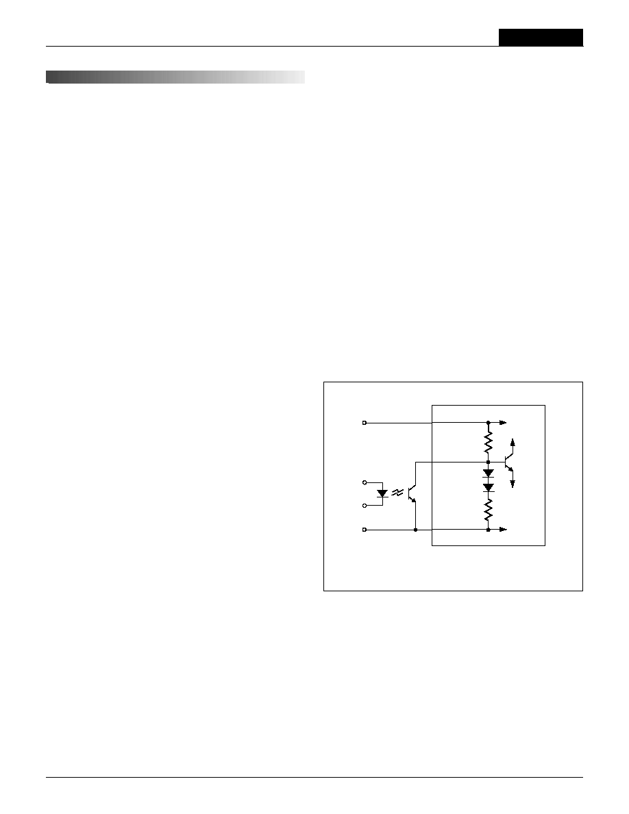
On/Off Control (Standard)
The On/Off Control pin (pin 3) may be used for remote on/off operation.
As shown in Figure 5, the control pin is referenced to the ≠Input (pin 1) and
has an internal pull-up resistor (28.7k
, 75k and 100k respectively for
D12, D24 and D48 models) to the +Input (pin 4). The standard UCP converter
is designed so that it is enabled when the control pin is left open and disabled
when the control pin is pulled low (to less than +0.8V relative to ≠Input). When
left open, pin 3 is pulled up to approximately 5V on "D24" models and 8V
on "D48" models.
Dynamic control of the on/off function is best accomplished with a mechanical
relay or an open-collector/open-drain drive circuit (optically isolated if appro-
priate). The drive circuit should obviously be able to sink approximately 1mA
when activated and withstand more than 10 Volts when deactivated.
Applying an external voltage to pin 3 when no input power is applied to
the converter can cause permanent damage to the converter. The on/off
control function, however, is designed such that the converter can be disabled
(pin 3 pulled low) while input power is ramping up and then "released" once
the input has stabilized. Under these circumstances, it takes approximately
30ms for the output of the fully loaded DC/DC to ramp up and settle to within
rated accuracy.
For UCP converters confi gured with the negative-polarity option on the On/Off
Control pin ("N" suffi x added to part number), operation is exactly opposite
to that described above.
T E C H N I C A L N O T E S
3
1
4
+INPUT
≠INPUT
ON/OFF
CONTROL
Figure 5. Driving the On/Off Control Pin
Input Reverse-Polarity Protection
Upon applying a reverse-polarity voltage to the DC/DC converter, an internal
diode will be forward biased and draw excessive current from the power
source. Therefore, it is required that the input current be limited be either an
appropriately rated input fuse or a current limited power source.
XCP Series
4 0 - 7 5 W , S I N G L E O U T P U T D C / D C C O N V E R T E R S
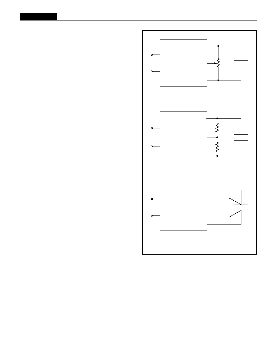
Output Trimming
V
OUT
may be trimmed ±5% via a single trimpot or fi xed resistor. As shown
in Figure 6, the trimpot should be connected between +Output (pin 5) and
≠Output (pin 9) with its wiper connected to Trim (pin 7). A trimpot can also be
used to determine the value of a single fi xed resistor which can be connected
between pin 7 (Trim) and pin 5 (+Output) to trim "down" the output voltage,
or between pins 7 (Trim) and 9 (≠Output) to trim "up" the output voltage, as
shown in Figure 7. Fixed resistors should be metal-fi lm types with absolute
TCR's less than 100ppm/∞C to ensure stability.
The Sense Pins
Switching DC/DC converters incorporate a feedback loop that continuously
monitors the difference between the output voltage and an internal precision
reference. In situations in which load currents and/or conductor impedances
are relatively high, there may be unacceptable voltage drops between the
converter output and its load. The purpose of the Sense pins (pins 6 and 8)
is to monitor and feed back the output voltage at the load, rather than at the
output of the converter, and to adjust the converter output as necessary to
maintain the load voltage at its desired level.
The Sense pins (which the converter output sees as having an effective 10
Ohm line impedance) should be connected across the output voltage at the
load and not at the output of the converter. See Figure 8. The Sense pins
then function similar to the Trim pin, and they effectively have the same ±5%
compensation range. If, for example, the combination of load current and line
impedance causes a 5V output to drop to +4.75V at its load (a 5% drop), the
sense function will compensate by raising the output voltage at the converter
to +5.25V. If the load voltage drops to +4.5V, the sense function will not be
able to compensate for the full drop, and other measures (like reducing line
impedance) must be taken.
If you are using both the external Trim and Sense functions, you must not
attempt to force the converter output voltage more than 5% above its initial,
"untrimmed" value.
When UCP DC/DC Converters are tested for output accuracy during fi nal
test, the Sense pins are connected directly to their respective output pins.
+INPUT
≠INPUT
TRIM
LOAD
20k
9
5-10
Turns
+OUTPUT
4
1
5
9
7
≠OUTPUT
Trim
Down
Trim Up
4
1
LOAD
+INPUT
≠INPUT
+OUTPUT
TRIM
5
9
7
≠OUTPUT
Figure 6. Trim Connections Using a Trimpot
Figure 7. Trim Connections Using Fixed Resistors
+INPUT
≠INPUT
LOAD
+OUTPUT
4
1
5
9
8
≠OUTPUT
+SENSE
≠SENSE
6
Figure 8. Sense Connections Made at the Load
Case Connection
Unlike most other DC/DC converters, UCP DC/DC's do not have their metal
case connected to one of their input pins. The "uncommitted" case is con-
nected to pin 2 which, depending upon your system confi guration, should
be connected to either +Input (pin 4), ≠Input (pin 1), ≠Output (pin 9), or
earth ground.
6
UCP Models
4 0 - 7 5 W , S I N G L E O U T P U T D C / D C C O N V E R T E R S
DS-0437A 10/02
DATEL makes no representation that the use of its products in the circuits described herein, or the use of other technical information contained herein, will not infringe upon existing or future patent rights. The descriptions contained herein
do not imply the granting of licenses to make, use, or sell equipment constructed in accordance therewith. Specifi cations are subject to change without notice. The DATEL logo is a registered DATEL, Inc. trademark.
DATEL (UK) LTD. Tadley, England Tel: (01256)-880444
DATEL S.A.R.L. Montigny Le Bretonneux, France Tel: 01-34-60-01-01
DATEL GmbH M¸nchen, Germany Tel: 89-544334-0
DATEL KK Tokyo, Japan Tel: 3-3779-1031, Osaka Tel: 6-6354-2025
DATEL, Inc. 11 Cabot Boulevard, Mansfi eld, MA 02048-1151
Tel: (508) 339-3000 (800) 233-2765 Fax: (508) 339-6356
Internet: www.datel.com Email: sales@datel.com
ISO 9001 REGISTERED
INNOVATION and EX C ELL E N C E
Æ
Æ
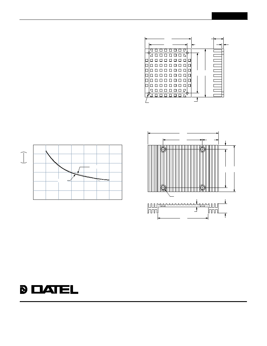
Optional Heat Sinks (Part Number HS-CP)
2.000
(50.80)
2.30
(58.42)
1.900
(48.26)
2.40
(60.96)
0.20
(5.08)
0.147 DIA. (3.734)
(4 PLACES)
0.20
(5.08)
0.50 (12.70) TYP.
051 (12.95) MAX.
0.10
(2.54)
TOP VIEW
MATERIAL: BLACK ANODIZED ALUMINUM
4 MOUNTING SCREWS AND 0.009 (0.229)
THICK THERMAL PAD INCLUDED
Optional Heat Sink (Part Number HS-CPLP2)
3.50
(88.90)
0.75
(19.05)
0.20
(5.08)
0.140 THRU AND COUNTERSINK
90∞ TO 0.26 (4 PLACES)
2.000
(50.80)
1.900
(48.26)
2.30
(58.42)
0.47
(11.94)
MATERIAL: BLACK ANODIZED ALUMINUM
2.48
(62.99)
0.16
(4.06)
Heat Sinks for UCP Series
DATEL offers two standard heat sinks that can be mounted to the half-brick
package to extend the converter's operating temperature range. Along with
the standard 2.3" x 2.4" x 0.5" (HS-CP) heat sink, DATEL has designed
a low-profi le heat sink for height-restricted applications. This new heat sink
(HS-CPLP2) is designed with radiant fi ns that extend 0.51" beyond either
side of the 2.4" dimension of the BCP package. The convenience of this
design is that the fi nned extensions protrude only 0.31" below the top surface
of the DC/DC converter, allowing components with a profi le height less than
0.2" to be mounted on the pc board below the heat sink. Therefore, while
the surface area of the low-profi le heat sink measures 2.3" x 3.5", pcb real
estate is unaffected.
For optimum thermal performance in a natural convection application, the
low-profi le heat sink should be mounted with the fi ns vertically oriented. Both
models are shipped with 0.009" sellf-adhesive thermal pad and mounting
screws.
Note: When mounting the heat sink to the UCP converter:
1. Maximum applied torque is 6 in-lbs.
2. Minimum thread engagement of the mounting screws is 12mm deep.
6
5
4
3
2
1
0
0
100
200
300
400
500
600
700
AIR VELOCITY (FT./MIN.)
HS-CP
THERMAL RESIST
ANCE
∞
C
WA
T
T
HS-CPLP2
Figure 9. HS-CP and HS-CPLP2 Heat Sink Performance Vs. Air Flow
7