Single Output
UEP Models
Features
High-Density, 2" x 1"
1-4.5 Amp, 11-18 Watt DC/DC's
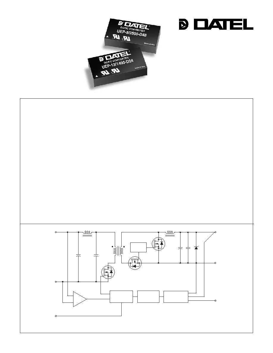
Figure 1. Simplifi ed Schematic
The UEP 11-18Watt series DC/DC converter is an alternative pinout for DATEL's
fl agship A-Series. An external pinout confi guration affords the design layout to be
oriented for optimal thermal performance thereby increasing available output power
as much as 20%. Available in a 1" x 2" package, these converters can deliver up to
18 Watts at the same ambient temperatures as their 15 Watt counterparts.
By combining a high-frequency (340kHz), high-effi ciency (to 88%), synchronous-
rectifi er topology with the newest components and time-tested, fully automated,
SMT-on-pcb construction, these UEP Models are able to bring you 11-18W in the
standard 2" x 1" package from which most competitors can only get 5-10W. All
UEP's deliver their full output power over ambient temperature ranges from ≠40
∞
C
to as high as +70
∞
C (model and input voltage dependent) without heat sinks or
supplemental forced-air cooling. Devices derate to +100
∞
C.
Output voltages are 3.3, 5, 12 or 15 Volts. Input voltage ranges are 10-18V
("D12" models), 18-36V ("D24" models) or 36-75V ("D48") models. All models fea-
ture input pi fi lters, input undervoltage and overvoltage lockout, input reverse-polarity
protection, output overvoltage protection, output current limiting, and continuous
short-circuit protection. Standard features also include On/Off Control and output-
trim. All models are certifi ed to IEC950, UL60950 and EN60950 safety requirements
for OPERATIONAL insulation. "D48" models (36-75V inputs) are CE marked.
UEP 11-18W DC/DC's are packaged in low-cost, light-weight, diallyl phthalate
(UL94V-0 rated) plastic packages with standoffs. EMC compliance is achieved via a
low-noise design rather than through expensive metal shielding.
INNOVATION and EX C ELL E N C E
Æ
Æ
+INPUT
+OUTPUT
PWM
CONTROLLER
OPTO
ISOLATION
UVLO & OVLO
COMPARATORS
SWITCH
CONTROL
REFERENCE &
ERROR AMP
≠OUTPUT
TRIM
≠INPUT
ON/OFF
CONTROL
1.5, 1.8, 2.5, 3.3V and 5V-output models use the synchronous-rectifi er confi guration shown above.
12V and 15V-output models employ a standard, diode-rectifi cation architecture.
DATEL, Inc., Mansfi eld, MA 02048 (USA) ∑ Tel: (508)339-3000, (800)233-2765 Fax: (508)339-6356 ∑ Email: sales@datel.com ∑ Internet: www.datel.com
Models Include
3.3V @ 4.5A
5V @ 3.5A
12V @ 1.2A
15V @ 1A
Choice of 3 input ranges:
10-18V, 18-36V, 36-75V
Guaranteed effi ciencies to 86%
11-18 Watts in 1" x 2" package
340kHz synchronous-rectifi er topologies
≠40 to +60/70
∞
C ambient w/o derating
Fully isolated (1500Vdc); I/O protected
Trim and On/Off Control
UL60950/EN60950 certifi ed
CE mark (75V
IN
models)

UEP Series
1 1 - 1 8 W , S I N G L E O U T P U T D C / D C C O N V E R T E R S
1.00
(25.40)
0.10
(2.54)
0.100
(2.54)
0.10
(2.54)
0.400
(10.16)
0.400
(10.16)
0.600
(15.24)
1.800
(45.72)
0.800
(20.32)
BOTTOM VIEW
1
2
3
4
5
6
PLASTIC CASE
STANDOFF
0.020 (0.51)
2.00
(50.80)
0.20 MIN
(5.08)
0.49
(12.45)
0.040 ±0.002 DIA.
(1.016 ±0.051)
DIMENSIONS ARE IN INCHES (MM)
R/N (mVp-p) Regulation
(Max.)
Effi ciency
Package
V
OUT
I
OUT
V
IN
Nom.
Range
I
IN
(Case,
Model
(Volts)
(mA)
Typ. Max.
Line Load
(Volts) (Volts) (mA) Min.
Typ. Pinout)
2
Performance Specifi cations and Ordering Guide
Typical at T
A
= +25∞C under nominal line voltage and full-load conditions, unless otherwise noted.
Ripple/Noise (R/N) is tested/speciifed over a 20MHz bandwidth. All models are specifi ed with no
external input/output capacitors.
UEP-3.3/4500-D12 3.3 4500 85 100 ±0.2% ±0.5% 12 10-18 80/1490 84.5% 83.5% C15, P21
UEP-3.3/4500-D24 3.3 4500 85 100 ±0.2% ±0.5% 24 18-36 50/730 87.5% 85.5% C15, P21
UEP-3.3/4500-D48 3.3 4500 85 100 ±0.2% ±0.5% 48 36-75 35/360 87.5% 85.5% C15, P21
UEP-5/3500-D12 5 3500 85 100 ±0.2% ±0.5% 12 10-18 120/1760 86% 84% C15, P21
UEP-5/3500-D24 5 3500 85 100 ±0.2% ±0.5% 24 18-36 65/850 88% 86% C15, P21
UEP-5/3500-D48 5 3500 85 100 ±0.2% ±0.5% 48 36-75 40/430 88% 86% C15, P21
UEP-12/1400-D12 12 1400 85 100 ±0.2% ±0.5% 12 10-18 60/1650 85% 82.5% C15, P21
UEP-12/1400-D24 12 1400 85 100 ±0.2% ±0.5% 24 18-36 45/800 87% 85% C15, P21
UEP-12/1400-D48 12 1400 85 100 ±0.2% ±0.5% 48 36-75 20/400 87% 85% C15, P21
UEP-15/1200-D12 15 1200 85 100 ±0.2% ±0.5% 12 10-18 60/1760 85% 82.% C15, P21
UEP-15/1200-D24 15 1200 85 100 ±0.2% ±0.5% 24 18-36 45/860 87% 85% C15, P21
UEP-15/1200-D48 15 1200 85 100 ±0.2% ±0.5% 48 36-75 30/430 87% 85% C15, P21
Wide Range Input
Output Confi guration:
U = Unipolar
Nominal Output Voltage:
3.3, 5, 12 or 15 Volts
Maximum Output Current
in mA
Input Voltage Range:
D12 = 10-18 Volts (12V nominal)
D24 = 18-36 Volts (24V nominal)
D48 = 36-75 Volts (48V nominal)
U EP
4500
-
/
D48 N
-
3.3
Optional Functions
UEP converters are designed such that the 12 and 15V
OUT
models can be
confi gures for either positive logic on/off control (no suffi x) or negative logic ("N"
suffi x). 3.3 and 5V
OUT
models are available with positive logic only (no suffi x).
No Suffi x On/Off Control function (positive polarity) on pin 3
N On/Off Control function (negative polarity) on pin 3.
(12V and 15V models only.
Case C15
N Suffi x
Available for 12V
OUT
and 15V
OUT
Models
Output
Input
P A R T N U M B E R S T R U C T U R E
M E C H A N I C A L S P E C I F I C A T I O N S
Pin Function
P21
1
+Input
2
Input
Return
3 On/Off
Control
4
+Output
5 Output
Return
6
Trim
I/O Connections
Load regulation is specifi ed over 10%-100% load conditions.
Nominal line voltage, no-load/full-load conditions.

UEP Models
1 1 - 1 8 W , S I N G L E O U T P U T D C / D C C O N V E R T E R S
3
Performance/Functional Specifi cations
Typical @ T
A
= +25∞C under nominal line voltage and full-load conditions, unless noted.
Input Voltage:
Continuous:
D12 Models 22 Volts
D24 Models 44 Volts
D48 Models 88 Volts
Transient (100msec):
D12 Models 50 Volts
D24 Models 50 Volts
D48 Models 100 Volts
Input Reverse-Polarity Protection Current must be <10 Amps. Brief
duration only. Fusing recommended.
Output Overvoltage Protection:
3.3V Outputs 4.5 Volts, unlimited duration
5V/12V/15V Outputs 6.8/15/18 Volts, unlimited duration
Output Current Hiccup. Devices can
withstand sustained output short
circuits without damage.
Case Temperature +100∞C
Storage Temperature ≠40 to +105∞C
Lead Temperature (soldering, 10 sec.) +300∞C
These are stress ratings. Exposure of devices to any of these conditions may adversely
affect long-term reliability. Proper operation under conditions other than those listed in the
Performance/Functional Specifi cations Table is not implied.
Absolute Maximum Ratings
Input
Input Voltage Range:
D12A Models 10-18 Volts (12V nominal)
D24A Models 18-36 Volts (24V nominal)
D48A Models 36-75 Volts (48V nominal)
Overvoltage Shutdown:
D12A Models 18.5-21 Volts (20V typical)
D24A Models 37-40 Volts (38V typical)
D48A Models 77-81 Volts (78.5V typical)
Start-Up Threshold:
D12A Models 9.3-9.8 Volts (9.6V typical)
D24A Models 16.5-18 Volts (17V typical)
D48A Models 34-36 Volts (35V typical)
Undervoltage Shutdown:
D12A Models 7-8.5 Volts (8V typical)
D24A Models 15.5-17.5 Volts (16.5V typical)
D48A Models 32.5-35.5 Volts (34.5V typical)
Input Current:
Normal Operating Conditions See Ordering Guide
Standby Mode (Off, OV, UV) 5mA
Input Filter Type Pi
Reverse-Polarity Protection Brief duration, 10A maximum
On/Off Control (Optional, Pin 3):
D12, D24, & D48 Models On = open or 13V - +V
IN
, I
IN
= 50µA max.
Off = 0-0.8V, I
IN
= 1mA max.
D12N, D24N, & D48N Models On = 0-0.5V, I
IN
= 50µA max.
Off = open or 2.4-10V, I
IN
= 3.7mA max.
Output
V
OUT
Accuracy (50% load): ±1.5%, maximum
Minimum Loading:
3.3V/5V Outputs No load
12V/15V
Outputs 25mA
Ripple/Noise (20MHz BW)
See Ordering Guide
Line/Load Regulation See Ordering Guide
Effi ciency See Ordering Guide
Isolation Voltage:
Input-to-Output 1500Vdc minimum
Isolation Capacitance 470pF
Isolation Resistance 100M
Current Limit Inception:
3.3V Models 5.5-7 Amps
5V Models 5.5-6 Amps
12V Models 1.9-2.7 Amps
15V Models 1.5-2.1 Amps
Short Circuit:
Hiccup, indefi nite
Average Current 3 Amps maximum
V
OUT
Trim Range ±5%
Overvoltage Protection Zener/transorb clamp, magnetic feedback
Temperature Coeffi cient ±0.04% per ∞C.
Dynamic Characteristics
Transient Response (50-100% load) 200µsec max. to ±1.5% of fi nal value
Start-Up Time:
V
IN
to V
OUT
50msec
On/Off to V
OUT
30msec
Switching Frequency 340kHz (±40kHz)
Environmental
Operating Temperature (Ambient):
Without Derating
≠40 to +60/70∞C
With Derating to +100∞C (See Derating Curves)
Case Temperature:
Maximum Allowable +100∞C
Storage Temperature ≠40 to +105∞C
Physical
Dimensions 2" x 1" x 0.49" (51 x 25 x 12.45mm)
Shielding None
Case Material Diallyl phthalate, meets EN60950
fl amability requirements
Pin Material Brass, solder coated
Weight 1.4 ounces (39.7 grams)
All models are specifi ed with no external input/output capacitors.
See Minimum Output Loading Requirements under Technical Notes.
See Technical Notes for details.
The On/Off Control is designed to be driven with open-collector logic or the application of
appropriate voltages (referenced to ≠Input (Pin 2)). Applying a voltage to the On/Off Control
pin when no input voltage is applied to the converter may cause permanent damage.
See Technical Notes.
Output noise may be further reduced with the addition of external output capacitors.
See Technical Notes.
Operating temperature range without derating is model and input-voltage dependent.
See Temperature Derating.
UEP Series
1 1 - 1 8 W , S I N G L E O U T P U T D C / D C C O N V E R T E R S
4
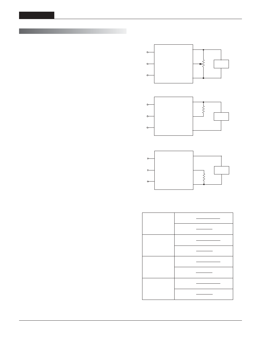
Trimming Output Voltages
These converters have a trim capability (pin 6) that allows users to adjust the
output voltage ±5%. Adjustments to the output voltage can be accomplished
via a trim pot, Figure 2, or a single fi xed resistor as shown in Figures 3 and 4.
A single fi xed resistor can increase or decrease the output voltage depending
on its connection. Fixed resistors should have an absolute TCR less than
100ppm/∞C to minimize sensitivity to changes in temperature.
A single resistor connected from the Trim (pin 6) to the +Output (pin 4), see
Figure 3, will decrease the output voltage. A resistor connected from the Trim
(pin 6) to ≠Output (pin 5) will increase the output voltage.
20k
5-22
Turns
+INPUT
+OUTPUT
TRIM
≠INPUT
ON/OFF
CONTROL
1
2
3
4
LOAD
≠OUTPUT
5
6
+INPUT
+OUTPUT
TRIM
≠INPUT
ON/OFF
CONTROL
1
2
3
4
LOAD
R
TRIM DOWN
≠OUTPUT
5
6
+INPUT
+OUTPUT
≠OUTPUT
TRIM
≠INPUT
ON/OFF
CONTROL
1
2
3
4
5
LOAD
6
R
TRIM UP
Figure 2. Trim Connections Using A Trim Pot
Figure 4. Trim Connections To Increase Output Voltage Using Fixed Resistors
Figure 3. Trim Connections To Decrease Output Voltage Using Fixed Resistors
≠16.9
DOWN
R
T
(k
) =
3.3 ≠ V
O
2.49(V
O
≠ 1.27)
UEP-3.3/4500-D12
UEP-3.3/4500-D24
UEP-3.3/4500-D48
≠16.9
UP
R
T
(k
) =
V
O
≠ 3.3
3.16
≠15
DOWN
R
T
(k
) =
5 ≠ V
O
2.49(V
O
≠ 2.527)
UEP-5/3500-D12
UEP-5/3500-D24
UEP-5/3500-D48
≠15
UP
R
T
(k
) =
V
O
≠ 5
6.292
≠49.9
DOWN
R
T
(k
) =
12 ≠ V
O
6.34(V
O
≠ 5.714)
UEP-12/1400-D12
UEP-12/1400-D24
UEP-12/1400-D48
≠49.9
UP
R
T
(k
) =
V
O
≠ 12
36.23
≠63.4
DOWN
R
T
(k
) =
15 ≠ V
O
7.87(V
O
≠ 7.136)
UEP-15/1200-D12
UEP-15/1200-D24
UEP-15/1200-D48
≠63.4
UP
R
T
(k
) =
V
O
≠ 15
56.16
Accuracy of adjustment is subject to tolerances or resistor values
and factory-adjusted output accuracy. V
O
= desired output voltage.
Model
Trim
Equation
T E C H N I C A L N O T E S
Floating Outputs
Since these are isolated DC/DC converters, their outputs are "fl oating."
Designers will usually use the ≠Output (pin 5) as the ground/return of the
load circuit. You can, however, use the +Output (pin 4) as ground/return to
effectively reverse the output polarity.
Minimum Output Loading Requirements
3.3 and 5V models employ a synchronous-rectifi er design topology. All
models regulate within spec and are stable under no-load conditions. 12/15V
models employ a traditional forward, diode-rectifi cation architecture and
require 25mA loading to achieve their listed regulation specs. Operation
under 25mA load conditions will not damage the 12/15V devices; however
they may not meet all listed specifi cations.
Filtering and Noise Reduction
All UEP Series DC/DC Converters achieve their rated ripple and noise
specifi cations with no external input/output capacitors. In critical applications,
input/output noise may be further reduced by installing external I/O caps.
Input capacitors should be selected for bulk capacitance, low ESR and high
rms-ripple-current ratings. Output capacitors should be selected for low ESR
and appropriate frequency response. All caps should have appropriate volt-
age ratings and be mounted as close to the converters as possible.
The most effective combination of external I/O capacitors will be a function of
your particular load and layout conditions. Our Applications Engineers recom-
mend potential solutions and can discuss the possibility of our modifying a
given device's internal fi ltering to meet your specifi c requirements. Contact
our Applications Engineering Group for additional details.
Input Fusing
Certain applications and/or safety agencies may require the installation of
fuses at the inputs of power conversion components. Fuses should also be
used if the possibility of sustained, non-current-limited, input-voltage polarity
reversals exists. For DATEL UER 11-18 Watt DC/DC Converters, you should
use slow-blow type fuses with values no greater than the following.
V
IN
Range Fuse Value
D12 Models 3 Amps
D24 Models 2 Amps
D48 Models 1 Amp
Trim adjustment greater than 5% can have an adverse effect on the convert-
er's performance and is not recommended.
UEP Models
1 1 - 1 8 W , S I N G L E O U T P U T D C / D C C O N V E R T E R S
Start-Up Threshold and Undervoltage Shutdown
Under normal start-up conditions, UEP DC/DC Converters will not begin
to regulate properly until the ramping input voltage exceeds the Start-Up
Threshold. Once operating, devices will turn off when the applied voltage
drops below the Undervoltage Shutdown point. Devices will remain off as
long as the undervoltage condition continues. Units will automatically re-start
when the applied voltage is brought back above the Start-Up Threshold. The
hysteresis built into this function avoids an indeterminate on/off condition at
a single input voltage. See Performance/Functional Specifi cations table for
actual limits.
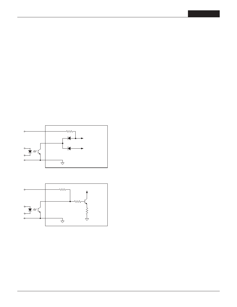
On/Off Control
The input-side, remote On/Off Control function (pin 4) can be ordered to
operate with either polarity (12 and 15 Volt models only). Positive-polarity
devices (standard, no part-number suffi x) are enabled when pin 3 is left open
or is pulled high (+13V to V
IN
applied with respect to ≠Input, pin 2, (see Figure
2). Positive-polarity devices are disabled when pin 5 is pulled low (0-0.8V
with respect to ≠Input). Negative-polarity devices are off when pin 3 is open
or pulled high (+2.4V to +10V), and on when pin 3 is pulled low (0-0.5V).
See Figure 3.
Dynamic control of the remote on/off function is best accomplished with
a mechanical relay or an open-collector/open-drain drive circuit (optically
isolated if appropriate). The drive circuit should be able to sink appropriate
current (see Performance Specs) when activated and withstand appropriate
voltage when deactivated.
Applying an external voltage to pin 3 when no input power is applied to the
converter can cause permanent damage to the converter.
Sync Function
(Optional)
Contact DATEL for further information.
Start-Up Time
The V
IN
to V
OUT
start-up time is the interval of time where the input voltage
crosses the turn-on threshold point, and the fully loaded output voltage
enters and remains within its specifi ed accuracy band. Actual measured
times will vary with input source impedance, external input/output capac-
itance, and load. The UHE Series implements a soft start circuit
that limits the duty cycle
of the PWM controller at power up, thereby limiting the Input Inrush current.
The On/Off Control to V
OUT
start-up time assumes the converter has its
nominal input voltage applied but is turned off via the On/Off Control pin.
The specifi cation defi nes the interval between the time at which the converter
is turned on and the fully loaded output voltage enters and remains within
its specifi ed accuracy band. Similar to the V
IN
to V
OUT
start-up, the On/Off
Control to V
OUT
start-up time is also governed by the internal soft start
circuitry and external load capacitance.
Input Overvoltage/Undervoltage Shutdown and Start-Up Threshold
Under normal start-up conditions, devices will not begin to regulate until the
ramping-up input voltage exceeds the Start-Up Threshold Voltage (35V for
"D48" models). Once operating, devices will not turn off until the input volt-
age drops below the Undervoltage Shutdown limit (34V for "D48" models).
Subsequent re-start will not occur until the input is brought back up to the
Start-Up Threshold. This built in hysteresis prevents any unstable on/off
situations from occurring at a single input voltage.
Input voltages exceeding the input overvoltage shutdown specifi cation listed
in the Performance/Functional Specifi cations will cause the device to shut-
down. A built-in hysteresis of 0.6 to 1.6 Volts for all models will not allow the
converter to restart until the input voltage is suffi ciently reduced.
Input Reverse-Polarity Protection
If the input-voltage polarity is accidentally reversed, an internal diode will
become forward biased and likely draw excessive current from the power
source. If the source is not current limited (<10A) nor the circuit appropriately
fused, it could cause permanent damage to the converter.
Current Limiting
When output increases to 120% to 190% of the rated output current,
the DC/DC converter will go into a current limiting mode. In this condition
the output voltage will decrease proportionately with increases in output cur-
rent, thereby maintaining a somewhat constant power dissipation. This is
commonly referred to as power limiting. Current limit inception is defi ned
as the point where the full-power output voltage falls below the specifi ed
tolerance. See Performance/Functional Specifi cations. If the load current
being drawn from the converter is signifi cant enough, the unit will go into a
short circuit condition. See "Short Circuit Condition."
3
2
1
200k
+INPUT
13V CIRCUIT
5V CIRCUIT
≠INPUT
ON/OFF
CONTROL
3
2
1
+INPUT
≠INPUT
ON/OFF
CONTROL
Figure 2. Driving the Positive Polarity On/Off Control Pin
Figure 3. Driving the Negative Polarity On/Off Control Pin
5

UEP Series
1 1 - 1 8 W , S I N G L E O U T P U T D C / D C C O N V E R T E R S
Short Circuit Condition
When a converter is in current limit mode the output voltages will drop as
the output current demand increases. If the output voltage drops too low, the
magnetically coupled voltage used to develop primary side voltages will also
drop, thereby shutting down the PWM controller.
Following a time-out period, the PWM will restart, causing the output voltage
to begin ramping to its appropriate value. If the short-circuit condition per-
sists, another shutdown cycle will be initiated. This on/off cycling is referred
to as "hiccup" mode. The hiccup cycling reduces the average output current,
thereby preventing internal temperatures from rising to excessive levels. The
UEP is capable of enduring an indefi nite short circuit output condition.
Thermal Shutdown
These UEP converters are equipped with Thermal Shutdown Circuitry. If
environmental conditions cause the internal temperature of the DC/DC
converter rises above the designed operating temperature, a precision tem-
perature sensor will power down the unit. When the internal temperature
decreases below the threshold of the temperature sensor the unit will self
start. See Performance/Functional Specifi cations.
Output Overvoltage Protection
UEP output voltages are monitored for an overvoltage condition via a
comparator which is optically coupled to the primary side. If the output
voltage should rise to a level which could be damaging to the load circuitry,
the sensing circuitry will power down the PWM controller causing the output
voltages to decrease. Following a time-out period the PWM will restart,
causing the output voltages to ramp to their appropriate values. If the fault
condition persists, and the output voltages again climb to excessive levels,
the overvoltage circuitry will initiate another shutdown cycle. This on/off
cycling is referred to as "hiccup" mode.
T E M P E R A T U R E D E R A T I N G
Output P
o
wer (W
atts)
Ambient Temperature (
∞
C)
Temperature Derating Curves for 3.3V Output Models
17.5
15
12.5
10
7.5
5
2.5
0
≠40
0
40
45
50
55
60
65
70
75
80
85
90
95
100
V
IN
= 18V-27V (D24)
V
IN
= 36V-48V (D48)
V
IN
= 18V-30V (D24)
V
IN
= 36V-60V (D48)
V
IN
= 12V (D12)
V
IN
= 18V-36V (D24)
V
IN
= 36V-75V (D48)
Output P
o
wer (W
atts)
Ambient Temperature (
∞
C)
Temperature Derating Curves for 5V Output Models
20
17.5
15
12.5
10
7.5
5
2.5
0
≠40
0
40
45
50
55
60
65
70
75
80
85
90
95
100
V
IN
= 18V-27V (D24)
V
IN
= 36V-48V (D48)
V
IN
= 18V-30V (D24)
V
IN
= 36V-60V (D48)
V
IN
= 12V (D12)
V
IN
= 18V-36V (D24)
V
IN
= 36V-75V (D48)
Output P
o
wer (W
atts)
Ambient Temperature (
∞
C)
Temperature Derating Curves for 12V Output Models
18
16
14
12
10
8
6
4
2
0
≠40
0
40
45
50
55
60
65
70
75
80
85
90
95
100
V
IN
= 18V-27V (D24)
V
IN
= 36V-48V (D48)
V
IN
= 18V-30V (D24)
V
IN
= 36V-60V (D48)
V
IN
= 12V (D12)
V
IN
= 18V-36V (D24)
V
IN
= 36V-75V (D48)
Output P
o
wer (W
atts)
Ambient Temperature (
∞
C)
Temperature Derating Curves for 15V Output Models
20
18
16
14
12
10
8
6
4
2
0
≠40
0
40
45
50
55
60
65
70
75
80
85
90
95
100
V
IN
= 18V-27V (D24)
V
IN
= 36V-48V (D48)
V
IN
= 18V-30V (D24)
V
IN
= 36V-60V (D48)
V
IN
= 12V (D12)
V
IN
= 18V-36V (D24)
V
IN
= 36V-75V (D48)
6

UEP Models
1 1 - 1 8 W , S I N G L E O U T P U T D C / D C C O N V E R T E R S
E F F I C I E N C Y V S . L I N E A N D L O A D
7
90
85
80
75
70
65
60
55
50
45
40
UEP-3.3/4500-D12 Efficiency vs. Line Voltage and Load Current
0.4
0.91
1.43
1.94
2.45
2.96
3.48
3.99
4.5
Load Current (Amps)
Efficienc
y (
%
)
V
IN
= 10V
V
IN
= 12V
V
IN
= 18V
90
85
80
75
70
65
60
55
50
45
40
UEP-3.3/4500-D24 Efficiency vs. Line Voltage and Load Current
0.4
0.91
1.43
1.94
2.45
2.96
3.48
3.99
4.5
Load Current (Amps)
Efficienc
y (
%
)
V
IN
= 18V
V
IN
= 24V
V
IN
= 36V
90
85
80
75
70
65
60
55
50
45
40
UEP-3.3/4500-D48 Efficiency vs. Line Voltage and Load Current
0.4
0.91
1.43
1.94
2.45
2.96
3.48
3.99
4.5
Load Current (Amps)
Efficienc
y (
%
)
V
IN
= 36V
V
IN
= 48V
V
IN
= 75V
90
85
80
75
70
65
60
55
50
45
40
UEP-5/3500-D12 Efficiency vs. Line Voltage and Load Current
0.3
0.7
1.1
1.5
1.9
2.3
2.7
3.1
3.5
Load Current (Amps)
Efficienc
y (
%
)
V
IN
= 10V
V
IN
= 12V
V
IN
= 18V
90
85
80
75
70
65
60
55
50
45
40
UEP-5/3500-D24 Efficiency vs. Line Voltage and Load Current
0.3
0.7
1.1
1.5
1.9
2.3
2.7
3.1
3.5
Load Current (Amps)
Efficienc
y (
%
)
V
IN
= 18V
V
IN
= 24V
V
IN
= 36V
90
85
80
75
70
65
60
55
50
45
40
UEP-5/3500-D48 Efficiency vs. Line Voltage and Load Current
0.3
0.7
1.1
1.5
1.9
2.3
2.7
3.1
3.5
Load Current (Amps)
Efficienc
y (
%
)
V
IN
= 36V
V
IN
= 48V
V
IN
= 75V

UEP Series
1 1 - 1 8 W , S I N G L E O U T P U T D C / D C C O N V E R T E R S
8
E F F I C I E N C Y V S . L I N E A N D L O A D
90
85
80
75
70
65
60
55
UEP-12/1400-D12 Efficiency vs. Line Voltage and Load Current
0.10
0.26
0.43
0.59
0.75
0.91
1.06
1.24
1.40
Load Current (Amps)
Efficienc
y (
%
)
V
IN
= 10V
V
IN
= 12V
V
IN
= 18V
90
85
80
75
70
65
60
55
UEP-12/1400-D24 Efficiency vs. Line Voltage and Load Current
0.10
0.26
0.43
0.59
0.75
0.91
1.06
1.24
1.40
Load Current (Amps)
Efficienc
y (
%
)
V
IN
= 18V
V
IN
= 24V
V
IN
= 36V
90
85
80
75
70
65
60
55
50
45
UEP-12/1400-D48 Efficiency vs. Line Voltage and Load Current
0.10
0.26
0.43
0.59
0.75
0.91
1.06
1.24
1.40
Load Current (Amps)
Efficienc
y (
%
)
V
IN
= 36V
V
IN
= 48V
V
IN
= 75V
90
85
80
75
70
65
60
55
UEP-15/1200-D12 Efficiency vs. Line Voltage and Load Current
0.10
0.24
0.38
0.51
0.65
0.79
0.93
1.06
1.2
Load Current (Amps)
Efficienc
y (
%
)
V
IN
= 10V
V
IN
= 12V
V
IN
= 18V
90
85
80
75
70
65
60
55
UEP-15/1200-D24 Efficiency vs. Line Voltage and Load Current
0.10
0.24
0.38
0.51
0.65
0.79
0.93
1.06
1.2
Load Current (Amps)
Efficienc
y (
%
)
V
IN
= 18V
V
IN
= 24V
V
IN
= 36V
90
85
80
75
70
65
60
55
50
UEP-15/1200-D48 Efficiency vs. Line Voltage and Load Current
0.10
0.24
0.38
0.51
0.65
0.79
0.93
1.06
1.2
Load Current (Amps)
Efficienc
y (
%
)
V
IN
= 36V
V
IN
= 48V
V
IN
= 75V
A Series
9 - 1 5 W , S I N G L E O U T P U T D C / D C C O N V E R T E R S
9
DATEL makes no representation that the use of its products in the circuits described herein, or the use of other technical information contained herein, will not infringe upon existing or future patent rights. The descriptions contained herein do
not imply the granting of licenses to make, use, or sell equipment constructed in accordance therewith. Specifi cations are subject to change without notice. The DATEL logo is a registered DATEL, Inc. trademark.
DATEL (UK) LTD. Tadley, England Tel: (01256)-880444
DATEL S.A.R.L. Montigny Le Bretonneux, France Tel: 01-34-60-01-01
DATEL GmbH M¸nchen, Germany Tel: 89-544334-0
DATEL KK Tokyo, Japan Tel: 3-3779-1031, Osaka Tel: 6-6354-2025
DS-0502 9/01
DATEL, Inc. 11 Cabot Boulevard, Mansfi eld, MA 02048-1151
Tel: (508) 339-3000 (800) 233-2765 Fax: (508) 339-6356
Internet: www.datel.com Email: sales@datel.com
Data Sheet Fax Back: (508) 261-2857
INNOVATION and EX C ELL E N C E
Æ
Æ
ISO-9001 REGISTERED
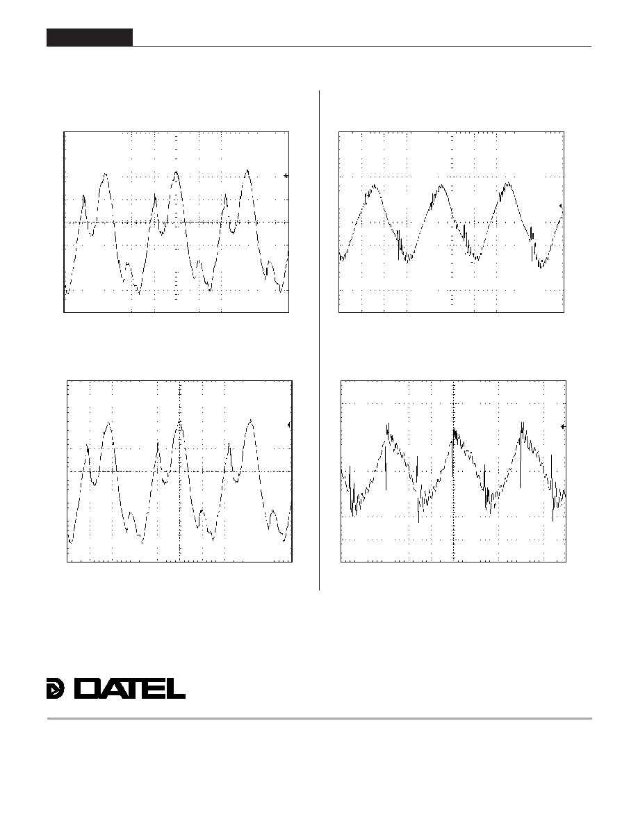
Typical Performance Curves
Output Ripple and Noise (PARD)
(V
IN
= nominal, 12V @ 1.4A, no external capacitors.)
20mV/div, 20MHz BW
Output Ripple and Noise (PARD)
(V
IN
= nominal, 15V @ 1.2A, no external capacitors.)
20mV/div, 20MHz BW
Output Ripple and Noise (PARD)
(V
IN
= nominal, 5V @ 3.5A, no external capacitors.)
20mV/div, 20MHz BW
Output Ripple and Noise (PARD)
(V
IN
= nominal, 3.3V @ 4.5A, no external capacitors.)