Single Output
UHE Models
Features
High Effi ciency, 1.6" x 2"
2-10 Amp, 12-30 Watt DC/DC's
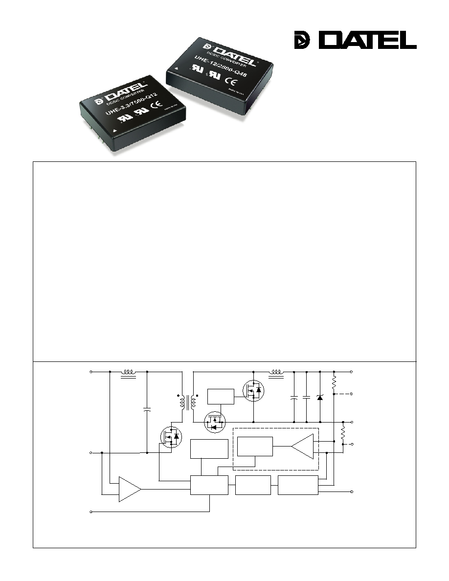
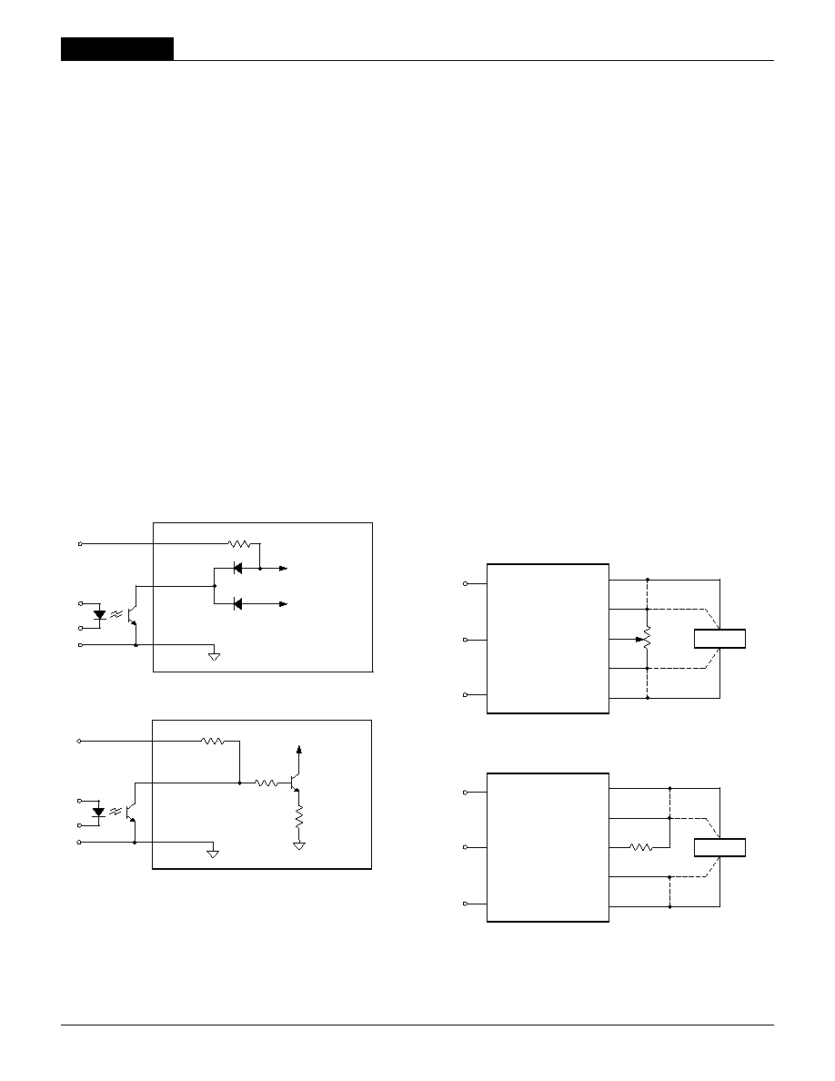
Figure 1. Simplifi ed Schematic
INNOVATION and EX C ELL E N C E
Æ
Æ
DATEL, Inc., Mansfi eld, MA 02048 (USA)
∑ Tel: (508)339-3000, (800)233-2765 Fax: (508)339-6356 ∑ Email: sales@datel.com ∑ Internet: www.datel.com
≠OUTPUT
≠SENSE
+INPUT
(4)
(6)
(1)
(2)
(5)
(7)
(8)
(9)
≠INPUT
PWM
CONTROLLER
REFERENCE &
ERROR AMP
THERMAL
SHUTDOWN
OPTO
ISOLATION
OPTO
ISOLATION
UVLO & OVLO
COMPARATORS
OVERVOLTAGE
COMPARATOR
ON/OFF
CONTROL
V
OUT
TRIM
+OUTPUT
+SENSE
SWITCH
CONTROL
Optional comparator feedback. Contact DATEL.
Sense pins are optional on 1.2-5V
OUT
models ("R" suffi x).
Housed in smaller, 1.6" x 2" x 0.40" (41 x 51 x 10.2mm) packages carrying the
standard 2" x 2" pinout, DATEL's new UHE Series DC/DC Converters deliver more
current/power (up to 10A/30W) than currently available from either package size.
The UHE 12-30W Series of high-effi ciency, isolated DC/DC's provide output power
ranging from 10 Amps @ 1.2V to 2 Amps @ 15V. Offering both 2:1 and 4:1 input
voltage ranges, UHE's meet V
IN
requirements from 9 to 75 Volts.
Taking full advantage of the synchronous-rectifi er, forward topology, UHE's boast
outstanding effi ciency (some models exceed 91%) enabling full-power operation to
ambient temperatures as high as +60∞C, without air fl ow. Assembled using fully
automated, SMT-on-pcb techniques, UHE's provide stable no-load operation, excel-
lent line (±0.1%) and load (±0.15%) regulation, quick step response (200µsec), and
low output ripple/noise (50-100mVp-p). Additionally, the UHE's unique output design
eliminates one of the topology's few shortcomings≠output reverse conduction.
All devices feature full I/O fault protection including: input overvoltage and under-
voltage shutdown, precise output overvoltage protection (a rarity on low-voltage
outputs), output current limiting, short-circuit protection, and thermal shutdown.
All UHE models incorporate a V
OUT
Trim function and an On/Off Control pin
(positive or negative polarity). Low-voltage models (1.2V to 5V) offer optional sense
pins facilitating either remote load regulation or current sharing for true N+1 redun-
dancy. All models are certifi ed to the BASIC insulation requirements of UL/EN60950,
and 48V
IN
(75V max.) models carry the CE mark.
!
The most I
OUT
/P
OUT
in this format
!
Lower priced than bricks
!
Small 1.6" x 2" x 0.4" plastic package
with standard 2" x 2" pinout
!
Output confi gurations:
1.2/1.5/1.8/2.5V
OUT
@ 10 Amps
3.3/5V
OUT
@ 25 Watts
5/12/15V
OUT
@ 30 Watts
!
Five input ranges from 9-75 Volts
!
Effi ciencies as high as 91.5%
!
Stable no-load operation
!
Optional Sense pins for low V
OUT
!
Thermal shutdown, I/O protected
!
1500 Vdc I/O BASIC Insulation
!
UL/EN60950 certifi ed; CE marked
NEW
Wide-Input-Range
"Q" Models
XHE Series
1 2 - 3 0 W , S I N G L E O U T P U T D C / D C C O N V E R T E R S
R/N (mVp-p) Regulation
(Max.)
Effi ciency
Package
V
OUT
I
OUT
V
IN
Nom.
Range
I
IN
(Case,
Model
(Volts) (Amps)
Typ. Max.
Line
Load
(Volts) (Volts) (mA/A) Min. Typ. Pinout)
2
Performance Specifi cations and Ordering Guide
Typical at T
A
= +25∞C under nominal line voltage and full-load conditions, unless noted.
Ripple/Noise (R/N) is tested/specifi ed over a 20MHz bandwidth. All models are specifi ed with
an external 0.47µF multi-layer ceramic capacitor installed across their output pins.
Devices have no minimum-load requirements and will regulate under no-load conditions.
Regulation specifi cations describe the output voltage deviation as the line voltage or load (with/
without sense option) is varied from its nominal/midpoint value to either extreme.
Nominal line voltage, no-load/full-load conditions.
* Pins 5 and 8 are
installed for optional
R-suffi x versions of
1.2-5V
OUT
models.
Output
Input
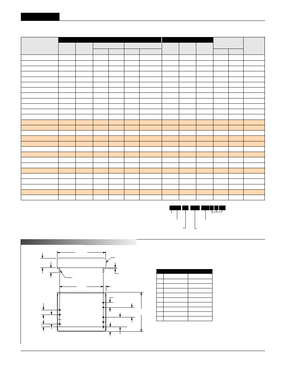
M E C H A N I C A L S P E C I F I C A T I O N S
Pin
Function P51
Function P52
1
+Input
+Input
2
≠Input
≠Input
3
No Pin
No Pin
4
On/Off Control
On/Off Control
5
No
Pin
+Sense*
6
+Output
+
Output
7
≠Output
≠Output
8
No
Pin
≠Sense*
9
Trim
Trim
I/O Connections
6
PLASTIC CASE
0.040 ±0.001 DIA.
(1.016 ±0.025)
0.20 MIN
(5.08)
2.00
(50.80)
0.40
(10.16)
STANDOFF
0.020 (0.51)
1.800
(45.72)
0.10
(2.54)
0.200
(5.08)
0.200
(5.08)
0.20
(5.08)
0.400
(10.16)
0.100
(2.54)
1.60
(40.64)
BOTTOM VIEW
DIMENSIONS ARE IN INCHES (MM)
9
5
8
7
1
2
4
3
0.400 (10.16)
2 EQ. SP. @
0.200 (5.08)
CASE C32
0.400
(10.16)
See last page
for complete
Part Number
Structure and
ordering details.
High Effi ciency
Unipolar
Nominal Output Voltage
Maximum Rated Output in mA
Input Voltage Range
U HE
7500
-
/
D48
-
3.3
N
Optional Functions
R LX
UHE-1.2/10000-D12 1.2 10 80 120 ±0.1% ±0.15/0.625% 12 9-18 35/1.27 80% 82% C32, P51/52
UHE-1.2/10000-D24 1.2 10 80 120 ±0.1% ±0.15/0.625% 24 18-36 35/0.63 81% 83% C32, P51/52
UHE-1.2/10000-D48 1.2 10 80 120 ±0.1% ±0.15/0.625% 48 36-75 35/0.31 81% 83% C32, P51/52
UHE-1.5/10000-D12 1.5 10 55 80 ±0.1% ±0.15/0.625% 12 9-18 35/1.56 81% 83% C32, P51/52
UHE-1.5/10000-D24 1.5 10 55 80 ±0.1% ±0.15/0.625% 24 18-36 35/0.76 84% 86% C32, P51/52
UHE-1.5/10000-D48 1.5 10 55 80 ±0.1% ±0.15/0.625% 48 36-75 35/0.38 82% 84% C32, P51/52
UHE-1.8/10000-D12 1.8 10 55 80 ±0.1% ±0.15/0.625% 12 9-18 35/1.81 84% 85.5% C32, P51/52
UHE-1.8/10000-D24 1.8 10 55 80 ±0.1% ±0.15/0.625% 24 18-36 35/0.89 85.5% 87% C32, P51/52
UHE-1.8/10000-D48 1.8 10 50 75 ±0.1% ±0.15/0.625% 48 36-75 35/0.46 83.5% 85% C32, P51/52
UHE-2.5/10000-D12 2.5 10 50 75 ±0.1% ±0.15/0.5% 12 9-18 35/2.48 85% 87% C32, P51/52
UHE-2.5/10000-D24 2.5 10 50 75 ±0.1% ±0.15/0.5% 24 18-36 35/1.23 86% 88% C32, P51/52
UHE-2.5/10000-D48 2.5 10 50 75 ±0.1% ±0.15/0.5% 48 36-75 35/0.61 86% 88% C32, P51/52
UHE-3.3/7500-Q12
3.3 7.5 50 70 ±0.1% ±0.15/0.3% 24 9-36 50/1.2 86.5% 88% C32, P51/52
UHE-3.3/7500-Q48
3.3 7.5 60 90 ±0.1% ±0.15/0.3% 48 18-75 38/0.6 87.5% 89.5% C32, P51/52
UHE-3.3/7500-D48 3.3 7.5 60 90 ±0.1% ±0.15/0.3% 48 36-75 35/0.6 88.5% 91% C32, P51/52
UHE-5/5000-Q12
5 5 50 70 ±0.1% ±0.15/0.3% 24 9-36 50/1.22 86% 87.5% C32, P51/52
UHE-5/5000-Q48
5 5 60 90 ±0.1% ±0.15/0.3% 48 18-75 35/0.6 87.5% 90% C32, P51/52
UHE-5/6000-D48 5 6 50 80 ±0.1% ±0.15/0.3% 48 36-75 45/0.73 89% 91.5% C32, P51/52
UHE-12/2500-Q12
12 2.5 100 120 ±0.2% ±0.3% 24 9-36 145/1.5 85% 87.5% C32, P51
UHE-12/2500-D12 12 2.5 65 100 ±0.2% ±0.3% 12 9-18 90/2.92 87% 89% C32, P51
UHE-12/2500-D24 12 2.5 65 100 ±0.2% ±0.3% 24 18-36 55/1.44 88% 90% C32, P51
UHE-12/2500-Q48
12 2.5 100 120 ±0.2% ±0.3% 48 18-75 45/0.72 88% 90.5% C32, P51
UHE-12/2500-D48 12 2.5 60 100 ±0.2% ±0.3% 48 36-75 30/0.7 90% 92% C32, P51
UHE-15/2000-D12 15 2 70 100 ±0.2% ±0.3% 12 9-18 110/2.92 87% 89% C32, P51
UHE-15/2000-D24 15 2 70 100 ±0.2% ±0.3% 24 18-36 70/1.44 88% 90% C32, P51
UHE-15/2000-Q48
15 2 100 150 ±0.2% ±0.3% 48 18-75 45/0.72 88% 90.5% C32, P51
UHE-15/2000-D48 15 2 70 100 ±0.2% ±0.3% 48 36-75 35/0.7 90% 92% C32, P51
UHE Models
1 2 - 3 0 W , S I N G L E O U T P U T D C / D C C O N V E R T E R S
3
Performance/Functional Specifi cations
Typical @ T
A
= +25∞C under nominal line voltage and full-load conditions, unless noted.
(1)
(2)
Input
Input Voltage Range:
D12 Models (start up at 10V max.) 9-18 Volts (12V nominal)
Q12 Models (start up at 10V max.) 9-36 Volts (24V nominal)
D24 Models 18-36 Volts (24V nominal)
Q48 Models 18-75 Volts (48V nominal)
D48 Models 36-75 Volts (48V nominal)
Overvoltage Shutdown:
D12 Models 18.5-23 Volts (20V typical)
Q12/D24 Models 37-42 Volts (39.5V typical)
D48/Q48 Models NA
Start-Up Threshold:
(2)
D12/Q12 Models 9.4-10 Volts (9.6V typical)
D24/Q48 Models 15.5-18 Volts (17V typical)
D48 Models 33.5-36 Volts (35V typical)
Undervoltage Shutdown:
(2)
D12/Q12 Models 7.0-8.8 Volts (8V typical)
D24/Q48 Models 15-17 Volts (16.5V typical)
D48 Models 32-35.5 Volts (34.5V typical)
Input Current:
Normal Operating Conditions See Ordering Guide
Standby Mode (Off, OV, UV) 5mA
Input Refl ected Ripple Current
(3)
10mAp-p
Input Filter Type LC
Reverse-Polarity Protection Brief duration, 5A maximum
Remote On/Off Control (Pin 4):
(4)
Positive Logic (Standard) On = open, open collector
(or +13V to V
IN
applied. I
IN
= 2.6mA max.)
Off = pulled low to 0-0.8V. I
IN
= 2mA max.
Negative Logic ("N" Suffi x Models) On = pulled low to 0-0.8V. I
IN
= 6mA max.
Off = open, open collector
(or +3.5V to V
IN
applied. I
IN
= 1mA max.)
Output
V
OUT
Accuracy (50% load):
Initial ±1.5% maximum
Temperatue Coeffi cient ±0.02% per ∞C
Extreme
(5)
±3%
Minimum Loading for Specifi cation:
(2)
No load
Ripple/Noise (20MHz BW)
(1)
See Ordering Guide
Line/Load Regulation See Ordering Guide
Effi ciency See Ordering Guide
V
OUT
Trim Range
(6)
±5% minimum
Remote Sense Compensation
(2)
±5%.
Isolation Voltage:
Input-to-Output 1500Vdc minimum (BASIC)
Isolation Capacitance 650pF
Isolation Resistance 100M
Current Limit Inception (@98%V
OUT
):
(7)
10 Amp Models 12-15 Amps
7.5 Amp Models 8.2-11.5 Amps
5/6 Amp Models 6.5-8.5 Amps
2.5 Amp Models 2.6-3.75 Amps
2.0 Amp Models 2.1-3 Amps
Short Circuit Current (Hiccup) 1.5-2.3 Amps
Output
Overvoltage Protection: Magnetic feedback
1.2V Outputs 1.5-2.1 Volts
1.5V Outputs 1.8-2.4 Volts
1.8V Outputs 2.2-2.8 Volts
2.5V Outputs 2.8 to 3.2 Volts
3.3V Outputs 4 to 4.8 Volts
5V Outputs 6.1-7.5 Volts
12V
Outputs 12.7-13.5 Volts
15V
Outputs 15.8-16.2 Volts
Maximum Capacitive Loading: 10,000µF (1.2-5V
OUT
)
(Low ESR capacitor) 2,000µF (12-15V
OUT
)
Dynamic Characteristics
Dynamic Load Response:
(50-100% load step to ±3% V
OUT
) 200µsec maximum
Start-Up Time:
(8)
4-8msec typical
V
IN
to V
OUT
and On/Off
to V
OUT
15msec maximum
Switching Frequency 150-350kHz (model dependent)
Environmental
MTBF
(9)
2.15 million hours
Operating Temperature (Ambient):
(10)
Without Derating +55 to +65∞C (model dependent)
With Derating To +100∞C (see Derating Curves)
Thermal Shutdown 105 to +125∞C
Storage Temperature ≠50 to +125∞C
Physical
Dimensions 1.6" x 2" x 0.40" (40.64 x 50.8 x 10.16mm)
Case Material Diallyl Phthalate
Pin Material Brass, solder coated
Weight: 1.51 ounces (46.9 grams)
Primary to Secondary Insulation Level Basic
(1)
All models are tested and specifi ed with a single, external, 47µF, multi-layer ceramic output
capacitor and no external input capacitors, unless otherwise noted. All models will effectively
regulate under no-load conditions (with perhaps a slight increase in output ripple/noise).
(2)
See Technical Notes/Performance Curves for additional explanations and details.
(3)
Input Ripple Current is tested/specifi ed over a 5-20MHz bandwidth with an external 33µF
input capacitor and a simulated source impedance of 220µF and 12µH. See I/O Filtering, Input
Ripple Current and Output Noise for details.
(4)
The On/Off Control is designed to be driven with open-collector (or equivalent) logic or the
application of appropriate voltages (referenced to ≠Input (pin 2)). Applying a voltage
to the On/Off Control pin when no input voltage is applied to the converter can cause permanent
damage. See Remote On/Off Control for more details.
(5)
Extreme Accuracy refers to the accuracy of either trimmed or untrimmed output voltages over all
normal operating ranges and combinations of input voltage, output load and temperature.
(6)
Tie the Output Trim pin (pin 9) to +Output (pin 6) for maximum trim down or to ≠Output (Output
Return/Common, pin 7) for maximum trim up. See Output Trimming for detailed trim equations.
(7)
The Current-Limit-Inception point is the output current level at which the converter's power-
limiting circuitry drops the output voltage 2% from its initial value. See Output Current Limiting
and Short-Circuit Protection for more details.
(8)
For Start-Up-Time specifi cations, output settling time is defi ned as the output voltage having
reached ±1% of its fi nal value at maximum load current.
(9)
MTBF's are calculated using TELCORDIA SR-332 Method 1 Case, ground fi xed, +25∞C ambient
air and full-load conditions. Contact DATEL for demonstrated life-test data.
(10)
All models are fully operational and meet all published specifi cations, including "cold start,"
at ≠40∞C.

XHE Series
1 2 - 3 0 W , S I N G L E O U T P U T D C / D C C O N V E R T E R S
T E C H N I C A L N O T E S
Input Voltage:
Continuous:
D12 Models 23 Volts
D24/Q12 Models 42 Volts
D48/Q48 Models 81 Volts
Transient (100msec):
D12 Models 50 Volts
D24/Q12 Models 50 Volts
D48/Q48 Models 100 Volts
On/Off Control (pin 4) Max. Voltages
Referenced to ≠Input (pin 2) +V
IN
Input Reverse-Polarity Protection Current must be <5 Amps. Brief
duration only. Fusing recommended.
Output Current Current limited. Devices can
withstand sustained output short
circuits without damage.
Case Temperature +100∞C
Storage Temperature ≠50 to +125∞C
Lead Temperature (soldering, 10 sec.) +300∞C
These are stress ratings. Exposure of devices to any of these conditions may adversely
affect long-term reliability. Proper operation under conditions other than those listed in the
Performance/Functional Specifi cations Table is not implied.
Absolute Maximum Ratings
4
Input Fusing
Certain applications and/or safety agencies may require the installation of
fuses at the inputs of power conversion components. Fuses should also be
used if the possibility of sustained, non-current-limited, input-voltage polarity
reversals exists. For DATEL UHE 12-30 Watt DC/DC Converters, you should
use slow-blow type fuses, installed in the ungrounded input supply line, with
values no greater than the following.
Model
Fuse
Values
in
Amps
Output/Input
D12 Q12 D24 Q48 D48
1.2
V
OUT
3 -- 2 -- 1
1.5
V
OUT
4 -- 2 -- 1
1.8
V
OUT
5
--
2.5
--
1
2.5
V
OUT
5
--
2.5
--
1
3.3
V
OUT
--
7.5
-
3
1.5
5
V
OUT
--
6
-
3
2
12
V
OUT
6
--
3
5
2
15
V
OUT
6
--
3
5
2
All relevant national and international safety standards and regulations must
be observed by the installer. For system safety agency approvals, the
converters must be installed in compliance with the requirements of the end-
use safety standard, e.g. IEC/EN/UL60950.
Input Undervoltage Shutdown and Start-Up Threshold
Under normal start-up conditions, devices will not begin to regulate until
the ramping-up input voltage exceeds the Start-Up Threshold Voltage (35V
for "D48" models). Once operating, devices will not turn off until the input
voltage drops below the Undervoltage Shutdown limit (34V for "D48" models).
Subsequent re-start will not occur until the input is brought back up to the
Start-Up Threshold. This built in hysteresis prevents any unstable on/off
situations from occurring at a single input voltage.
All D12/Q12 models will start-up at 9.6V typically and will then work within
specifi cations form 9-18V or 9-36V respectively.
Start-Up Time
The V
IN
to V
OUT
Start-Up Time is the interval of time between the point at
which the ramping input voltage crosses the Start-Up Threshold and the
fully loaded output voltage enters and remains within its specifi ed accuracy
band. Actual measured times will vary with input source impedance, external
input/output capacitance, and load. The UHE Series implements a soft start
circuit that limits the duty cycle of its PWM controller at power up, thereby
limiting the input inrush current.
The On/Off Control to V
OUT
start-up time assumes the converter has its
nominal input voltage applied but is turned off via the On/Off Control pin. The
specifi cation defi nes the interval between the point at which the converter
is turned on and the fully loaded output voltage enters and remains within
its specifi ed accuracy band. Similar to the V
IN
to V
OUT
start-up, the On/Off
Control to V
OUT
start-up time is also governed by the internal soft start
circuitry and external load capacitance.
The difference in start up time from V
IN
to V
OUT
and from On/Off Control to
V
OUT
is therefore insignifi cant.
Input Overvoltage Shutdown
All D12/Q12 and D24 Models of the UHE DC/DC converters are equipped
with Input Overvoltage Protection. Input voltages exceeding the input over-
voltage shutdown specifi cation listed in the Performance/Functional Specifi -
cations will cause the device to shutdown. A built-in hysteresis for all models
will not allow the converter to restart until the input voltage is suffi ciently
reduced.
All 48V
IN
models have this overvoltage shutdown function disabled because
of requirements for withstanding brief input surges to 100V for up to 100msec
without output voltage interruption.
Please contact DATEL to have input overvoltage shutdown for D48/Q48
models enabled.
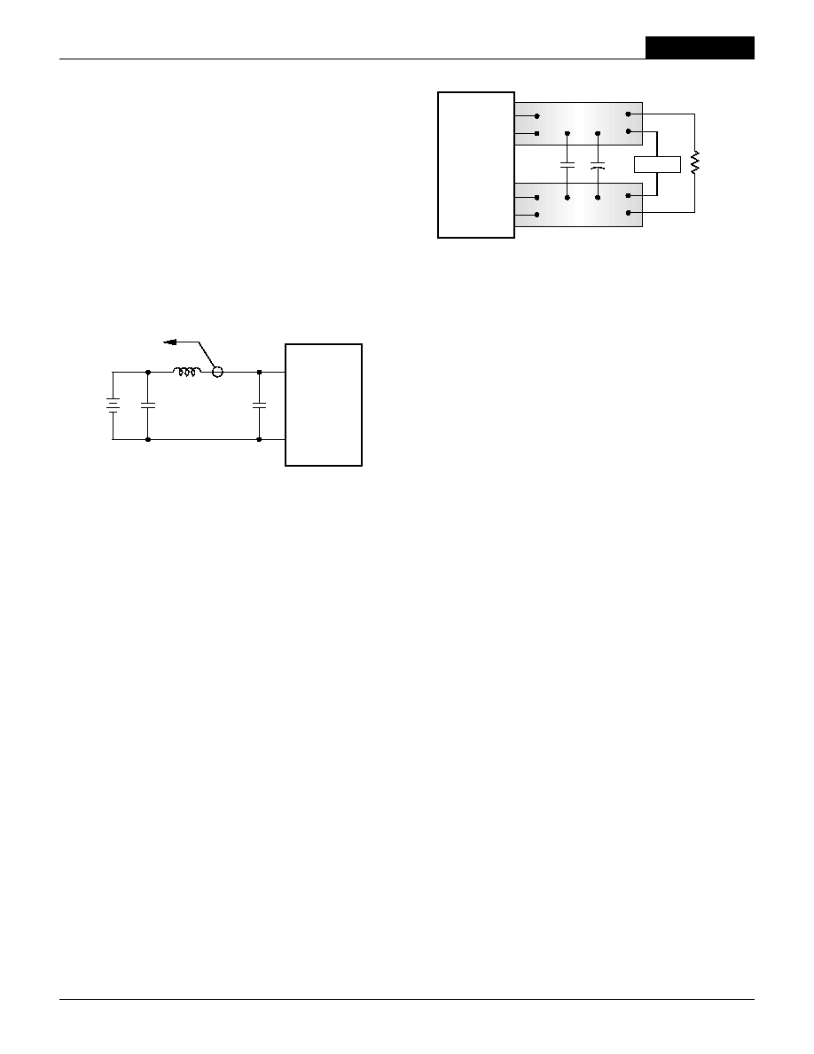
Input Source Impedance
UHE converters must be driven from a low ac-impedance input source.
The DC/DC's performance and stability can be compromised by the use of
highly inductive source impedances. The input circuit shown in Figure 2 is a
practical solution that can be used to minimize the effects of inductance in
the input traces. For optimum performance, components should be mounted
close to the DC/DC converter. If the application has a high source imped-
ance, low V
IN
models can benefi t of increased external input capacitance.
UHE Models
1 2 - 3 0 W , S I N G L E O U T P U T D C / D C C O N V E R T E R S
5
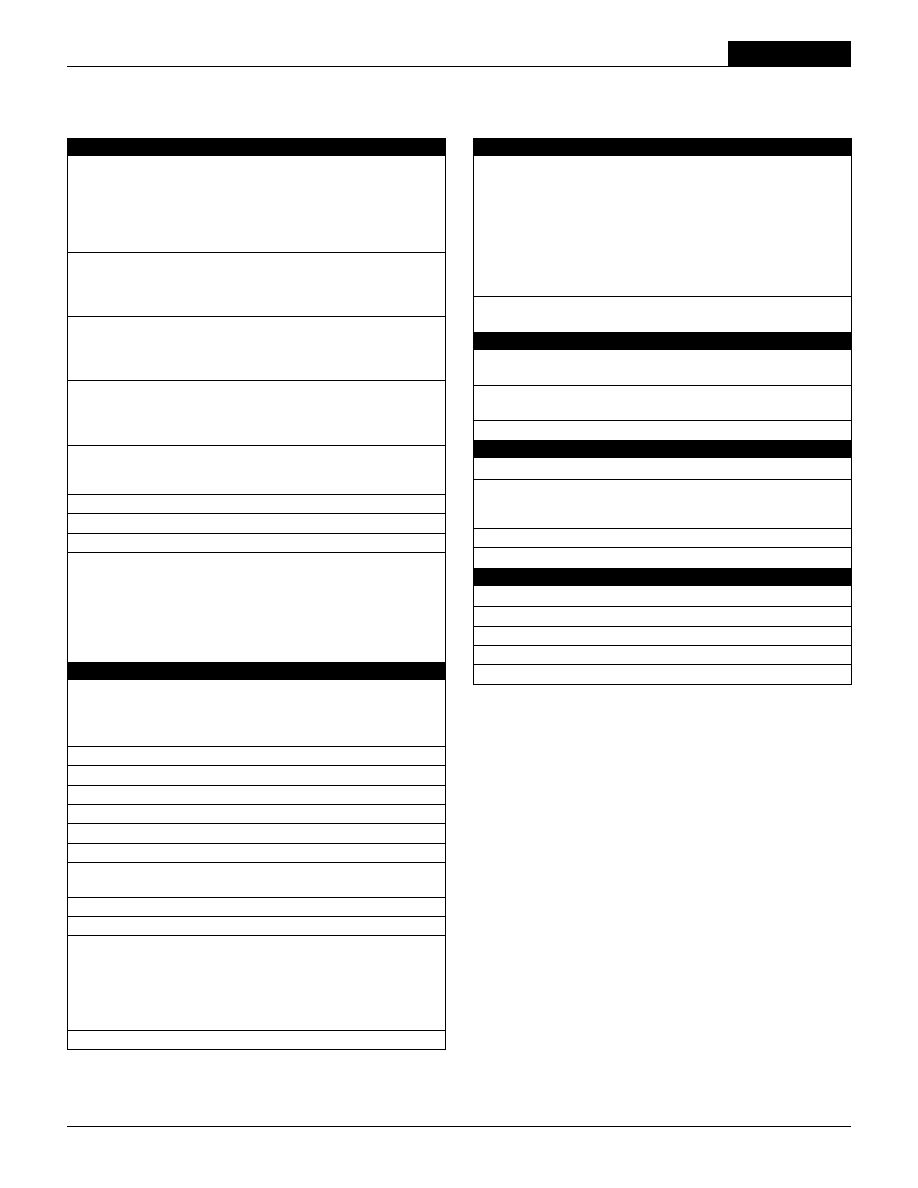
Figure 3. Measuring Output Ripple/Noise (PARD)
Figure 2. Measuring Input Ripple Current
C
IN
V
IN
C
BUS
L
BUS
C
IN
= 33µF, ESR < 700m
@ 100kHz
C
BUS
= 220µF, ESR < 100m
@ 100kHz
L
BUS
= 12µH
+INPUT
≠INPUT
CURRENT
PROBE
TO
OSCILLOSCOPE
+
≠
C1
C1 = 0.47µF CERAMIC
C2 = NA
LOAD 2-3 INCHES (51-76mm) FROM MODULE
C2
R
LOAD
COPPER STRIP
COPPER STRIP
SCOPE
+OUTPUT
≠OUTPUT
+SENSE
≠SENSE
In critical applications, output ripple/noise (also referred to as periodic and
random deviations or PARD) may be reduced below specifi ed limits using
fi ltering techniques, the simplest of which is the installation of additional
external output capacitors. These output caps function as true fi lter elements
and should be selected for bulk capacitance, low ESR and appropriate
frequency response. All external capacitors should have appropriate voltage
ratings and be located as close to the converter as possible. Temperature
variations for all relevant parameters should also be taken carefully into
consideration.
The most effective combination of external I/O capacitors will be a function
of line voltage and source impedance, as well as particular load and layout
conditions. Our Applications Engineers can recommend potential solutions
and discuss the possibility of our modifying a given device's internal fi ltering
to meet your specifi c requirements. Contact our Applications Engineering
Group for additional details.
In Figure 3, the two copper strips simulate real-world pcb impedances
between the power supply and its load. In order to minimize measurement
errors, scope measurements should be made using BNC connectors, or the
probe ground should be less than Ω inch and soldered directly to the fi xture.
Floating Outputs
Since these are isolated DC/DC converters, their outputs are "fl oating" with
respect to their input. Designers will normally use the ≠Output (pin 7) as the
ground/return of the load circuit. You can, however, use the +Output (pin 6) as
ground/return to effectively reverse the output polarity.
Minimum Output Loading Requirements
UHE converters employ a synchronous-rectifi er design topology and all
models regulate within spec and are stable under no-load to full load condi-
tions. Operation under no-load conditions however might slightly increase the
output ripple and noise.
Thermal Shutdown
These UHE converters are equipped with thermal-shutdown circuitry. If envi-
ronmental conditions cause the internal temperature of the DC/DC converter
to rise above the designed operating temperature, a precision temperature
sensor will power down the unit. When the internal temperature decreases
below the threshold of the temperature sensor, the unit will self start. See
Performance/Functional Specifi cations.
Output Overvoltage Protection
UHE output voltages are monitored for an overvoltage condition via magnetic
feedback. The signal is coupled to the primary side and if the output voltage
rises to a level which could be damaging to the load, the sensing circuitry
will power down the PWM controller causing the output voltages to decrease.
Following a time-out period the PWM will restart, causing the output voltages
to ramp to their appropriate values. If the fault condition persists, and the
output voltages again climb to excessive levels, the overvoltage circuitry will
initiate another shutdown cycle. This on/off cycling is referred to as "hiccup"
mode.
Contact DATEL for an optional output overvoltage monitor circuit using a
comparator which is optically coupled to the primary side thus allowing tighter
and more precise control.
Current Limiting
As soon as the output current increases to 10% to 50% above its rated value,
the DC/DC converter will go into a current-limiting mode. In this condition, the
output voltage will decrease proportionately with increases in output current,
thereby maintaining somewhat constant power dissipation. This is commonly
referred to as power limiting. Current limit inception is defi ned as the point
at which the full-power output voltage falls below the specifi ed tolerance.
See Performance/Functional Specifi cations. If the load current, being drawn
from the converter, is signifi cant enough, the unit will go into a short circuit
condition as specifi ed under "Performance."
I/O Filtering, Input Ripple Current, and Output Noise
All models in the UHE 12-30 Watt DC/DC Converters are tested/specifi ed for
input refl ected ripple current and output noise using the specifi ed external
input/output components/circuits and layout as shown in the following two
fi gures.
External input capacitors (C
IN
in Figure 2) serve primarily as energy-storage
elements, minimizing line voltage variations caused by transient IR drops in
conductors from backplane to the DC/DC. Input caps should be selected
for bulk capacitance (at appropriate frequencies), low ESR, and high rms-
ripple-current ratings. The switching nature of DC/DC converters requires
that dc voltage sources have low ac impedance as highly inductive source
impedance can affect system stability. In Figure 2, C
BUS
and L
BUS
simulate
a typical dc voltage bus. Your specifi c system confi guration may necessitate
additional considerations.
XHE Series
1 2 - 3 0 W , S I N G L E O U T P U T D C / D C C O N V E R T E R S
LOAD
+OUTPUT
≠INPUT
+INPUT
ON/OFF
CONTROL
TRIM
+SENSE
≠OUTPUT
≠SENSE
7
8
2
1
9
6
5
4
20k
5-22
TURNS
LOAD
R1
+OUTPUT
≠INPUT
+INPUT
ON/OFF
CONTROL
TRIM
+SENSE
≠OUTPUT
≠SENSE
7
8
2
1
9
6
5
4
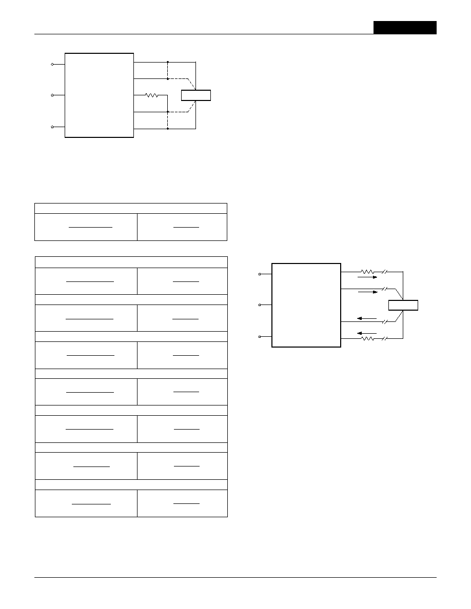
Figure 6. Trim Connections Using A Trimpot
Figure 7. Trim Connections To Decrease Output Voltages Using a Fixed Resistor
(for all models except 1.2V models which will increase V
OUT
)
6
Short Circuit Condition
When a converter is in current-limit mode, the output voltage will drop as
the output current demand increases. If the output voltage drops too low, the
magnetically coupled voltage used to develop primary side voltages will also
drop, thereby shutting down the PWM controller. Following a time-out period,
the PWM will restart causing the output voltages to begin ramping to their
appropriate values. If the short-circuit condition persists, another shutdown
cycle will be initiated. This on/off cycling is referred to as "hiccup" mode.
The hiccup cycling reduces the average output current, thereby preventing
internal temperatures from rising to excessive levels. The UHE is capable of
enduring an indefi nite short circuit output condition.
FEATURES AND OPTIONS
On/Off Control
The input-side, remote On/Off Control function (pin 4) can be ordered to
operate with either polarity:
Standard models are equipped with Positive-polarity (no part-number suffi x)
and these devices are enabled when pin 4 is left open (or is pulled high,
applying +13V to +V
IN
with respect to ≠Input, pin 2) as per Figure 4. Positive-
polarity devices are disabled when pin 4 is pulled low (0 to 0.8V with respect
to ≠Input).
Optional Negative-polarity devices ("N" suffi x) are off when pin 4 is left open
(or pulled high, applying +3.5V to +V
IN
), and on when pin 4 is pulled low (0 to
0.8V) with respect to ≠V
IN
as shown in Figure 5.
4
2
1
+INPUT
13V CIRCUIT
5V CIRCUIT
≠INPUT
ON/OFF
CONTROL
4
2
1
+INPUT
+V
CC
≠INPUT
ON/OFF
CONTROL
Figure 4. Driving the Positive Polarity On/Off Control Pin
Figure 5. Driving the Negative Polarity On/Off Control Pin
Dynamic control of the remote on/off function is best accomplished with a
mechanical relay or an open-collector/open-drain drive circuit (optically iso-
lated if appropriate). The drive circuit should be able to sink appropriate current
(see Performance Specs) when activated and withstand appropriate voltage
when deactivated. Applying an external voltage to pin 4 when no input power
is applied to the converter can cause permanent damage to the converter.
Trimming Output Voltage
UHE converters have a trim capability (pin 9) that allows users to adjust
the output voltages ±5% of V
OUT
. Adjustments to the output voltages can be
accomplished via a trim pot (Figure 6) or a single fi xed resistor as shown in
Figures 7 and 8. A single fi xed resistor can increase or decrease the output
voltage depending on its connection. The resistor should be located close to
the converter and have a TCR less than 100ppm/∞C to minimize sensitivity
to changes in temperature. If the trim function is not used, leave the trim
pin fl oating.
A single resistor connected from the Trim (pin 9) to the +Output (pin 6), or
+Sense where applicable, will decrease the output voltage for all models with
the exception of the 1.2V models, which will increase the output voltage in
this confi guration. A resistor connected from the Trim (pin 9) to the ≠Output
(pin 7), or ≠Sense where applicable, will increase the output voltage for all
models with the exception of the 1.2V models, which will decrease the output
voltage in this confi guration.
Trim adjustments greater than the specifi ed ±5% can have an adverse affect
on the converter's performance and are not recommended. Excessive voltage
differences between V
OUT
and Sense, in conjunction with trim adjustment of
the output voltage, can cause the overvoltage protection circuitry to activate
(see Performance Specifi cations for overvoltage limits). Power derating is
based on maximum output current and voltage at the converter's output pins.
Use of trim and sense functions can cause output voltages to increase,
thereby increasing output power beyond the converter's specifi ed rating or
cause output voltages to climb into the output overvoltage region. Therefore:
(V
OUT
at pins) x (I
OUT
) <= rated output power
UHE Models
1 2 - 3 0 W , S I N G L E O U T P U T D C / D C C O N V E R T E R S
Remote Sense (Optional on 1.2-5V
OUT
models)
Note: The Sense and V
OUT
lines are internally connected through low-value
resistors. Nevertheless, if the sense function is not used for remote regulation
the user should connect the +Sense to +V
OUT
and ≠Sense to ≠V
OUT
at the
DC/DC converter pins.
UHE series converters have a sense feature to provide point of use regula-
tion, thereby overcoming moderate IR drops in pcb conductors or cabling.
The remote sense lines carry very little current and therefore require minimal
cross-sectional-area conductors. The sense lines are used by the feedback
control-loop to regulate the output. As such, they are not low impedance
points and must be treated with care in layouts and cabling. Sense lines
on a pcb should be run adjacent to dc signals, preferably ground. In cables
and discrete wiring applications, twisted pair or other techniques should be
implemented.
UHE series converters will compensate for drops between the output
voltage at the DC/DC and the sense voltage at the DC/DC provided that:
[V
OUT
(+) ≠V
OUT
(≠)] ≠[Sense(+) ≠Sense (≠)]
5% V
OUT
Output overvoltage protection is monitored at the output voltage pin, not
the Sense pin. Therefore, excessive voltage differences between V
OUT
and
LOAD
R2
+OUTPUT
≠INPUT
+INPUT
ON/OFF
CONTROL
TRIM
+SENSE
≠OUTPUT
≠SENSE
7
8
2
1
9
6
5
4
LOAD
+OUTPUT
≠INPUT
Sense Current
Contact and PCB resistance
losses due to IR drops
Contact and PCB resistance
losses due to IR drops
Sense Return
+INPUT
ON/OFF
CONTROL
TRIM
+SENSE
≠OUTPUT
≠SENSE
7
8
2
1
9
5
I
OUT
Return
I
OUT
6
4
Figure 9. Remote Sense Circuit Confi guration
Figure 8. Trim Connections To Increase Output Voltages
(for all models except 1.2V models which will decrease V
OUT
)
7
Sense in conjunction with trim adjustment of the output voltage can cause the
overvoltage protection circuitry to activate (see Performance Specifi cations
for overvoltage limits). Power derating is based on maximum output current
and voltage at the converter's output pins. Use of trim and sense functions
can cause output voltages to increase thereby increasing output power
beyond the UHE's specifi ed rating or cause output voltages to climb into the
output overvoltage region. Therefore, the designer must ensure:
(V
OUT
at pins) x (I
OUT
)
rated output power
≠3.169
0.3232
UHE-1.5/10000-D12, -D24, -D48
UHE-1.8/10000-D12, -D24, -D48
UHE-2.5/10000-D12, -D24, -D48
UHE-3.3/7500-Q12, -Q24, -D48
V
O
≠ 1.5
R2
(k
) =
R1
(k
) =
≠3.169
0.459(V
O
≠ 0.7096)
1.5 ≠ V
O
1.2 ≠ V
O
≠7.596
0.9647
V
O
≠ 1.8
R2
(k
) =
R1
(k
) =
≠7.596
1.027(V
O
≠ 0.9352)
1.8 ≠ V
O
≠7.503
2.142
V
O
≠ 2.5
R2
(k
) =
R1
(k
) =
≠7.503
2.226(V
O
≠ 0.9625)
2.5 ≠ V
O
UHE-12/2500-D12, -D24, -D48
≠34.8
29.5
V
O
≠ 12
R2
(k
) =
R1
(k
) =
≠34.8
10(V
O
≠ 2.5)
12 ≠ V
O
UHE-15/2000-D12, -D24, -D48
≠43.3
37.875
V
O
≠ 15
R2
(k
) =
R1
(k
) =
≠43.3
13.3(V
O
≠ 2.5)
15 ≠ V
O
≠22.42
5.65
V
O
≠ 3.3
R2
(k
) =
R1
(k
) =
≠22.42
3.21(V
O
≠ 1.759)
3.3 ≠ V
O
UHE-5/5000-Q12, -Q48, UHE-5/6000-D48
≠15.52
5.58
V
O
≠ 5
R2
(k
) =
R1
(k
) =
≠15.52
2.15(V
O
≠ 2.592)
5 ≠ V
O
V
O
≠ 1.2
R1
(k
) =
R2
(k
) =
≠1.413
1.308(V
O
≠ 0.793)
≠1.413
1.037
UHE-1.2/10000-D12, -D24, -D48
Trim Up
Trim Up
Trim Down
Trim Down
Trim Equations
Note: Resistor values are in k
. Adjustment accuracy is subject to resistor
tolerances and factory-adjusted output accuracy. V
O
= desired output voltage.
XHE Series
1 2 - 3 0 W , S I N G L E O U T P U T D C / D C C O N V E R T E R S
8
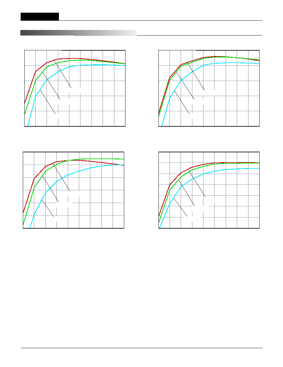
90
85
80
75
70
65
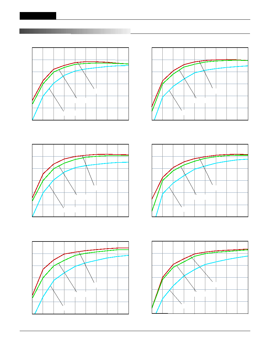
UHE-1.8/10000-D24 Efficiency vs. Load @ +25
∞
C Ambient
Output Current (Amps)
Efficienc
y (
%
)
1 2 3 4 5 6 7 8 9 10
V
IN
= 36V
V
IN
= 18V
V
IN
= 24V
90
85
80
75
70
65
60
55
UHE-1.8/10000-D48 Efficiency vs. Load @ +25
∞
C Ambient
Output Current (Amps)
Efficienc
y (
%
)
1 2 3 4 5 6 7 8 9 10
V
IN
= 75V
V
IN
= 36V
V
IN
= 48V
85
80
75
70
65
60
55
UHE-1.5/10000-D48 Efficiency vs. Load @ +25
∞
C Ambient
Output Current (Amps)
Efficienc
y (
%
)
1 2 3 4 5 6 7 8 9 10
V
IN
= 75V
V
IN
= 36V
V
IN
= 48V
90
85
80
75
70
65
UHE-1.5/10000-D24 Efficiency vs. Load @ +25
∞
C Ambient
Output Current (Amps)
Efficienc
y (
%
)
1 2 3 4 5 6 7 8 9 10
V
IN
= 36V
V
IN
= 18V
V
IN
= 24V
T Y P I C A L P E R F O R M A N C E C U R V E S
UHE Models
1 2 - 3 0 W , S I N G L E O U T P U T D C / D C C O N V E R T E R S
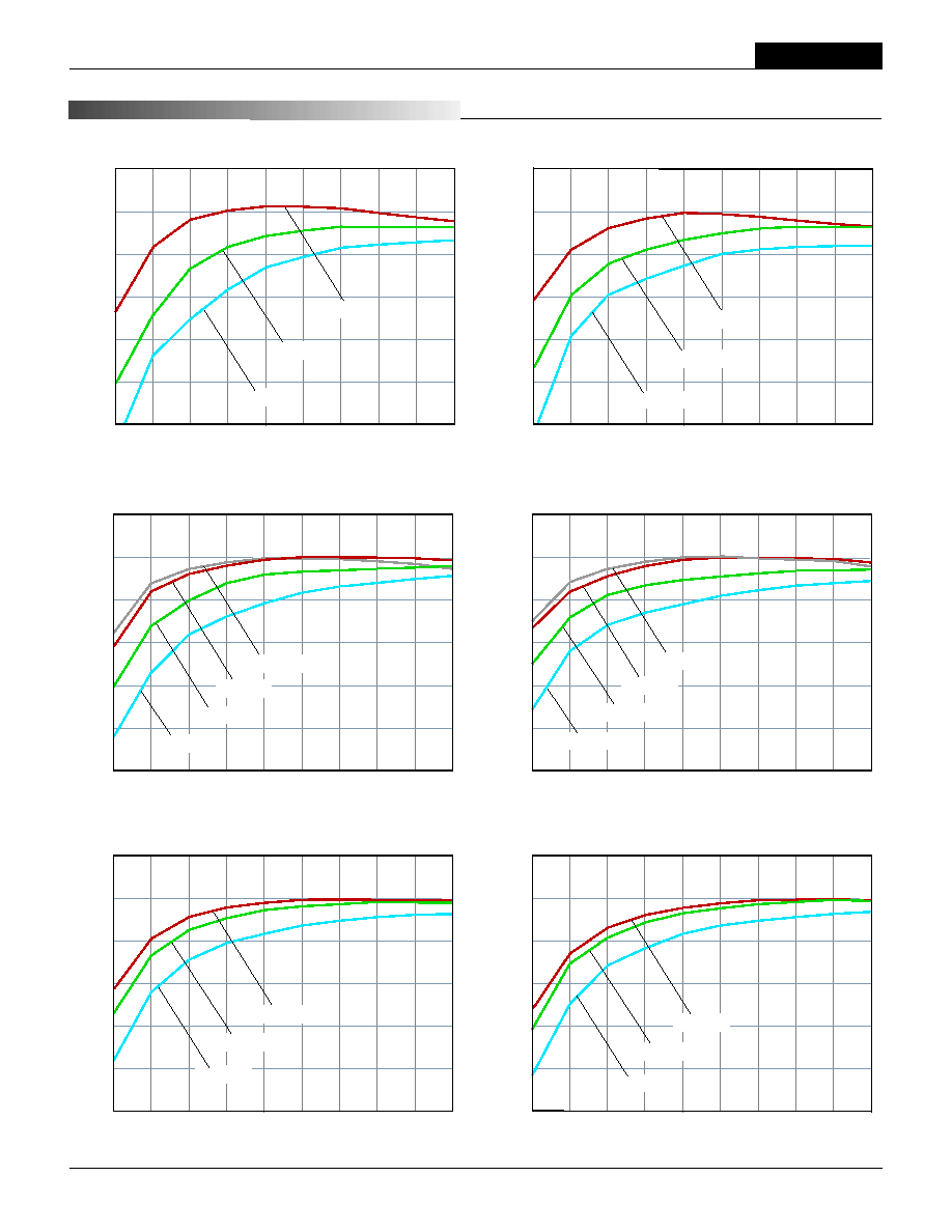
100
90
80
70
60
50
40
UHE-3.3/7500-D48 Efficiency vs. Load @ +25
∞
C Ambient
Output Current (Amps)
Efficienc
y (
%
)
0.75
1.5
2.25
3
3.75
4.5
5.25
6
6.75
7.5
V
IN
= 75V
V
IN
= 36V
V
IN
= 48V
100
90
80
70
60
50
40
UHE-3.3/7500-Q48 Efficiency vs. Load @ +25
∞
C Ambient
0.75
1.5
2.25
3
3.75
4.5
5.25
6
6.75
7.5
Output Current (Amps)
Efficienc
y (
%
)
V
IN
= 75V
V
IN
= 36V
V
IN
= 48V
V
IN
= 18V
100
90
80
70
60
50
40
UHE-5/6000-D48 Efficiency vs. Load @ +25
∞
C Ambient
0.6
1.2
1.8
2.4
3
3.6
4.2
4.8
5.4
6
Output Current (Amps)
Efficienc
y (
%
)
V
IN
= 75V
V
IN
= 36V
V
IN
= 48V
100
90
80
70
60
50
40
UHE-5/5000-Q48 Efficiency vs. Load @ +25
∞
C Ambient
0.5
1
1.5
2
2.5
3
3.5
4
4.5
5
Output Current (Amps)
Efficienc
y (
%
)
V
IN
= 75V
V
IN
= 36V
V
IN
= 48V
V
IN
= 18V
9
T Y P I C A L P E R F O R M A N C E C U R V E S
95
90
85
80
75
70
65
UHE-5/5000-Q12 Efficiency vs. Load @ +25
∞
C Ambient
Output Current (Amps)
Efficienc
y (
%
)
0.5 1.0 1.5 2 2.5 3 3.5 4 4.5 5
V
IN
= 36V
V
IN
= 9V
V
IN
= 24V
95
90
85
80
75
70
65
UHE-3.3/7500-Q12 Efficiency vs. Load @ +25
∞
C Ambient
Output Current (Amps)
Efficienc
y (
%
)
0.75
1.5
2.25
3
3.75
4.5
5.25
6
6.75
7.5
V
IN
= 36V
V
IN
= 9V
V
IN
= 24V
XHE Series
1 2 - 3 0 W , S I N G L E O U T P U T D C / D C C O N V E R T E R S
10
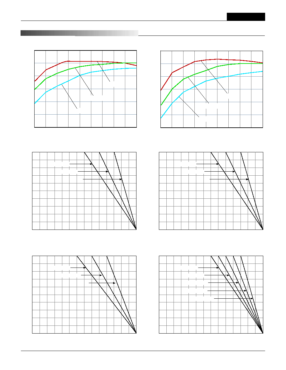
T Y P I C A L P E R F O R M A N C E C U R V E S
95
90
85
80
75
70
65
UHE-12/2500-D48 Efficiency vs. Load @ +25
∞
C Ambient
Output Current (Amps)
Efficienc
y (
%
)
0.25
0.5
0.75
1
1.25
1.5
1.75
2
2.25
2.5
V
IN
= 75V
V
IN
= 36V
V
IN
= 48V
95
90
85
80
75
70
65
UHE-15/2000-D24 Efficiency vs. Load @ +25
∞
C Ambient
Output Current (Amps)
Efficienc
y (
%
)
0.2
0.4
0.6
0.8
1
1.2
1.4
1.6
1.8
2
V
IN
= 36V
V
IN
= 18V
V
IN
= 24V
95
90
85
80
75
70
65
UHE-15/2000-D12 Efficiency vs. Load @ +25
∞
C Ambient
Output Current (Amps)
Efficienc
y (
%
)
0.2
0.4
0.6
0.8
1
1.2
1.4
1.6
1.8
2
V
IN
= 18V
V
IN
= 9V
V
IN
= 12V
95
90
85
80
75
70
65
UHE-15/2000-D48 Efficiency vs. Load @ +25
∞
C Ambient
Output Current (Amps)
Efficienc
y (
%
)
0.2
0.4
0.6
0.8
1
1.2
1.4
1.6
1.8
2
V
IN
= 75V
V
IN
= 36V
V
IN
= 48V
95
90
85
80
75
70
65
UHE-12/2500-D24 Efficiency vs. Load @ +25
∞
C Ambient
Output Current (Amps)
Efficienc
y (
%
)
0.25
0.5
0.75
1
1.25
1.5
1.75
2
2.25
2.5
V
IN
= 36V
V
IN
= 18V
V
IN
= 24V
95
90
85
80
75
70
65
UHE-12/2500-D12 Efficiency vs. Load @ +25
∞
C Ambient
Output Current (Amps)
Efficienc
y (
%
)
0.25
0.5
0.75
1
1.25
1.5
1.75
2
2.25
2.5
V
IN
= 18V
V
IN
= 9V
V
IN
= 12V
UHE Models
1 2 - 3 0 W , S I N G L E O U T P U T D C / D C C O N V E R T E R S
11
T Y P I C A L P E R F O R M A N C E C U R V E S
Output Ciurrent (Amps)
Ambient Temperature (∞C)
10
9
8
7
6
5
4
3
2
1
0
≠40 0 40 45 50 55 60 65 70 75 80 85 90 95 100
24V
IN
, 150LFM
24V
IN
, 300LFM
24V
IN,
STILL AIR
UHE-1.8/10000-D24 Temperature Derating
Output Ciurrent (Amps)
Ambient Temperature (∞C)
10
9
8
7
6
5
4
3
2
1
0
≠40 0 40 45 50 55 60 65 70 75 80 85 90 95 100
48V
IN,
STILL AIR
75V
IN
, 150LFM
75V
IN
, STILL AIR
48V
IN
, 150LFM
UHE-1.8/10000-D48 Temperature Derating
48V
IN
, 300LFM
Output Ciurrent (Amps)
Ambient Temperature (
∞C)
10
9
8
7
6
5
4
3
2
1
0
≠40 0 40 45 50 55 60 65 70 75 80 85 90 95 100
48V
IN
, 150LFM
48V
IN
, 300LFM
48V
IN,
STILL AIR
UHE-1.2/10000-D48 and UHE-1.5/10000-D48 Temperature Derating
Output Ciurrent (Amps)
Ambient Temperature (
∞C)
10
9
8
7
6
5
4
3
2
1
0
≠40 0 40 45 50 55 60 65 70 75 80 85 90 95 100
24V
IN
, 150LFM
24V
IN
, 300LFM
24V
IN,
STILL AIR
UHE-1.2/10000-D24 and UHE-1.5/10000-D24 Temperature Derating
95
90
85
80
75
70
65
UHE-12-2500-Q48 Efficiency vs. Load @ +25
∞
C Ambient
Output Current (Amps)
Efficienc
y (
%
)
0.25
0.5
0.75
1
1.25
1.5
1.75
2
2.25
2.5
V
IN
= 75V
V
IN
= 18V
V
IN
= 48V
95
90
85
80
75
70
65
UHE-15-2000-Q48 Efficiency vs. Load @ +25
∞
C Ambient
Output Current (Amps)
Efficienc
y (
%
)
0.2
0.4
0.6
0.8
1
1.2
1.4
1.6
1.8
2
V
IN
= 75V
V
IN
= 18V
V
IN
= 48V

XHE Series
1 2 - 3 0 W , S I N G L E O U T P U T D C / D C C O N V E R T E R S
12
Output P
o
wer (W
atts)
Ambient Temperature (∞C)
30
25
20
15
10
5
0
≠40 0 40 45 50 55 60 65 70 75 80 85 90 95 100
UHE-5/6000-D48 Temperature Derating
48V
IN,
STILL AIR
36V
IN,
STILL AIR
75V
IN
, STILL AIR
75V
IN
, 150LFM
75V
IN
, 300LFM
Output P
o
wer (W
atts)
Ambient Temperature (∞C)
30
25
20
15
10
5
0
≠40 0 40 45 50 55 60 65 70 75 80 85 90 95 100
UHE-3.3/7500-D48 Temperature Derating
48V
IN,
STILL AIR
36V
IN,
STILL AIR
75V
IN
, STILL AIR
75V
IN
, 150LFM
75V
IN
, 300LFM
Output P
o
wer (W
atts)
Ambient Temperature (
∞C)
30
25
20
15
10
5
0
≠40 0 40 45 50 55 60 65 70 75 80 85 90 95 100
UHE-12/2500 and UHE-15/2000 (All Models) Temperature Derating
48V
IN,
STILL AIR
(D48 Models Only)
12V
IN
, STILL AIR
24V
IN,
STILL AIR
(48V
IN
, Still Air for Q48 Models Only)
Output P
o
wer (W
atts)
Ambient Temperature (
∞C)
25
20
15
10
5
0
≠40 0 40 45 50 55 60 65 70 75 80 85 90 95 100
UHE-5/5000-Q12 Temperature Derating
24V
IN,
STILL AIR
36V
IN
, 150LFM
36V
IN
, STILL AIR
24V
IN
, 150LFM
24V
IN
, 300LFM
36V
IN
, 300LFM
Output P
o
wer (W
atts)
Ambient Temperature (∞C)
25
20
15
10
5
0
≠40 0 40 45 50 55 60 65 70 75 80 85 90 95 100
UHE-3.3/7500-Q12 Temperature Derating
24V
IN,
STILL AIR
36V
IN
, 150LFM
36V
IN
, STILL AIR
24V
IN
, 150LFM
24V
IN
, 300LFM
36V
IN
, 300LFM
T Y P I C A L P E R F O R M A N C E C U R V E S
XHE Series
1 2 - 3 0 W , S I N G L E O U T P U T D C / D C C O N V E R T E R S
DS-0501C 5/03
13
DATEL makes no representation that the use of its products in the circuits described herein, or the use of other technical information contained herein, will not infringe upon existing or future patent rights. The descriptions contained herein do
not imply the granting of licenses to make, use, or sell equipment constructed in accordance therewith. Specifi cations are subject to change without notice. The DATEL logo is a registered DATEL, Inc. trademark.
DATEL (UK) LTD. Tadley, England Tel: (01256)-880444
DATEL S.A.R.L. Montigny Le Bretonneux, France Tel: 01-34-60-01-01
DATEL GmbH M¸nchen, Germany Tel: 89-544334-0
DATEL KK Tokyo, Japan Tel: 3-3779-1031, Osaka Tel: 6-6354-2025
DATEL, Inc. 11 Cabot Boulevard, Mansfi eld, MA 02048-1151
Tel: (508) 339-3000 (800) 233-2765 Fax: (508) 339-6356
Internet: www.datel.com Email: sales@datel.com
Data Sheet Fax Back: (508) 261-2857
INNOVATION and EX C ELL E N C E
Æ
Æ
ISO 9001 REGISTERED
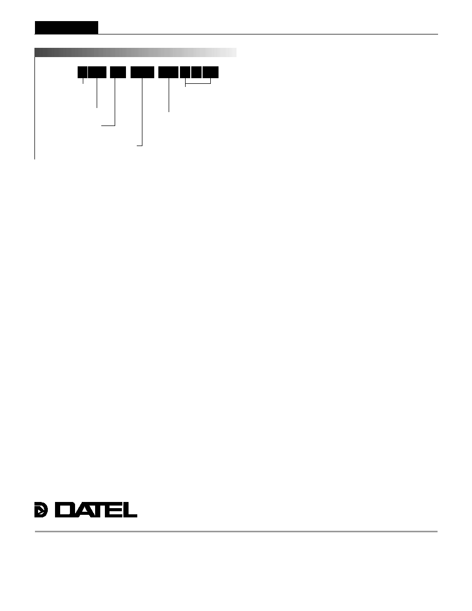
High Effi ciency
Output Confi guration:
U = Unipolar
Nominal Output Voltage:
1.2,1.5, 1.8, 2.5, 3.3, 5, 12 or 15 Volts
Maximum Rated Output
Current in mA
Input Voltage Range:
D12 = 9-18 Volts (12V nominal)
D24 = 18-36 Volts (24V nominal)
D48 = 36-75 Volts (48V nominal)
Q12 = 9-36 Volts (24V nominal)
Q48 = 18-75 Volts (48V nominal)
U HE
7500
-
/
D48
-
3.3
N
Optional functions
P A R T N U M B E R S T R U C T U R E
R
OPTIONS AND ADAPTATIONS
Optional Functions and Part Number Suffi xes
The versatile UHE, 12-30W DC/DC converters offer numerous electrical and
mechanical options. Per the Ordering Guide on page 2, the trailing DXX or
QXX (where XX stands for 12, 24 or 48V
IN
) in each part number pertains
to the base part number. Part-number suffi xes are added after this input
identifi cation, indicating the selection of standard options. The resulting part
number is a "standard product" and is available to any customer desiring that
particular combination of options.
The On/Off Control function on pin 4 employs a positive polarity (on = open or
"high," no suffi x). To request a negative polarity on this pin/function, add an "N"
suffi x to the part number. Standard models have no pins in the pins 5 and 8
positions. For 5-10A models (1.2-5V
OUT
), ±Sense pin/functions can be added
to these positions (see pinout P52) by adding an "R" suffi x. An "NR" suffi x can
be added for both negative-polarity and sense-pin options. See below.
Suffi x Description
Blank Positive polarity On/Off Control function (pin 4), V
OUT
trim (pin 9),
no Sense pins, pin length 0.2 inches (5.08 mm).
N
Add Negative polarity on the On/Off Control function, V
OUT
trim
(pin 9), no Sense pins.
R
Positive polarity on the On/Off Control function, V
OUT
trim (pin 9),
±Sense pins in the pin 5 and pin 8 positions (available for low
V
OUT
models only).
NR
Negative polarity on the On/Off Control function, V
OUT
trim (pin 9),
+/≠Sense pins in the pin 5 and pin 8 positions (available for low
V
OUT
models only).
L1
Trim the pin length to 0.110 ±0.010 inches (2.79 ±0.25mm).
This option requires a 100-piece minimum order quantity.
L2
Trim the pin length to 0.145 ±0.010 inches (3.68 ±0.25mm).
This option requires a 100-piece minimum order quantity.
Adaptations
There are various additional confi gurations available on UHE, 12-30W
DC/DC's. Because designating each of them with a standard part-number
suffi x is not always feasible, such are designated by DATEL in assigning a
5-digit "adaptation code" after the part-number suffi xes. Once a confi guration
has been requested by a customer and created by DATEL, the resulting prod-
uct is available to any customer as a standard off-the-shelf product. Contact
DATEL directly if you are interested in your own set of options/adaptations.
Our policy for minimum order quantities may apply. Consequently, the follow-
ing product is offered for sale:
UHE-5/6000-D48N--30749
Standard product, 48V
IN
, 5V/6A output with negative polarity on the
On/Off Control function, modifi ed Trim function (5% trim up = 9.09k
,
5% trim down = 3.83k
, compatible with UEP-30750), integrated soft
start and with input OVP and thermal shutdown removed.
Contact DATEL directly if you are interested in your own set of options/
adaptations. Further examples of such include, but are not limited to the
following:
∑ Competitor-compatible pin shape and/or length, instead of DATEL's
standard 40-mil round pins.
∑ Shielded metal case connected to the I/O pin of your choice.
∑ Electrical modifi cation of the V
OUT
Trim functionality/equations and/or the
On/Off Control function to be competitor-compatible.
∑ Raising the Input Overvoltage Lockout/Shutdown trip point to a level that
enables the device to experience brief input transients (of known peak
value and duration) without shutting down. For example, we can move the
threshold to +110V for applications that anticipate 100V, 100msec input
transients.
LX