upb25-40w.indd
INNOVATION and EX C ELL E N C E
®
®
Single Output
UPB Models
High-Effi ciency, Smaller-Package
25-40 Watt, DC/DC Converters
Features
DATEL's UPB Model, 25-40 Watt, single-output DC/DC power converters bring
you effi cient "on-board" power processing in a cost-effective smaller package with
a standard pinout. The 2" x 3" UPB "footprint" conforms with the industry-standard
pinout and pin geometries of most 3" x 3" devices (a 33% space savings) while
delivering as much as 60% more power (40W vs. 25W).
Applicable to a wide range of telecom, computer and other OEM applications,
UPB Model DC/DC's operate from four input voltage ranges (10-36V for "Q12"
models, 18-36V for "D24" models, 18-72V for "Q48" models, and 36-72V for "D48"
models). Available output voltages are 5, 12 and 15 Volts.
For improved reliability and affordability, DATEL exploits contemporary, high-
speed, automatic-assembly techniques to construct the UPB's traditional, fi eld-
proven, SMT-on-pcb designs. Devices employ corrosion-resistant steel cases with
heavy zinc top plates (traditionally referred to as baseplates). Heat generating trans-
former cores and power semiconductors are mounted directly to the baseplates,
which also have threaded inserts for optional add-on heat sinks or pcb mounting.
Temperature derating information is provided for operation with and without heat
sinks and forced air fl ow.
All devices feature input pi fi lters, input undervoltage and overvoltage shutdown,
output overvoltage protection, output current limiting, and thermal shutdown. All
UPB models are UL1950, CSA 22.2 No. 950, and IEC950 approved. Most have
been EMI/EMC characterized. Contact DATEL for the latest available information.
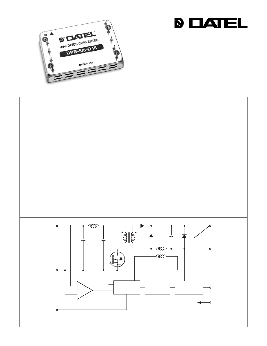
Figure 1. Simplifi ed Schematic
COMMON
+V
OUT
+V
IN
V
IN
PWM
CONTROLLER
ISOLATION
REFERENCE &
ERROR AMP
COMPARATORS
UVLO & OVLO
ON/OFF
CONTROL
(SYNC)
TRIM
CASE
25/30/35/40W output power
Standard pinout! Smaller size!
New 2" x 3" package fi ts 3" x 3" footprint
5V, 12V or 15V outputs
Four input voltage ranges:
10-36V, 18-36V
18-72V, 36-72V
High effi ciencies (to 85%)
Fully isolated, 750Vdc guaranteed
Input under and overvoltage lockout
Thermal shutdown
V
OUT
trim and on/off control
UL1950, CSA 22.2 No. 950, IEC950
Modifi cations and customs for OEM's
DATEL, Inc., Mansfi eld, MA 02048 (USA)
·
Tel: (508)339-3000, (800)233-2765 Fax: (508)339-6356
·
Email: sales@datel.com
·
Internet: www.datel.com
2 5 - 4 0 W , S I N G L E O U T P U T D C / D C C O N V E R T E R S
XPB Series
I/O
Connections
Pin Function
P14
1
No
Pin
2
Input
3
+Input
4
Case
5 On/Off
Control*
6
No
Pin
7
No
Pin
8
Common
9
+V
OUT
10
Trim
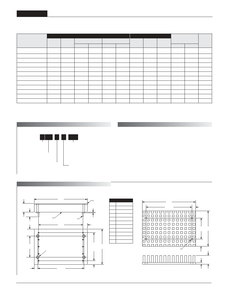
UPB-5/5-Q12 5 5 75 100 ±0.5% ±1% 24 10-36 50/1366 77% 79% C10, P14
UPB-5/6-Q48 5 6 75 100 ±0.5% ±1% 48 18-72 25/799 79% 80% C10, P14
UPB-5/7-D24 5 7 75 100 ±0.5% ±1% 24 18-36 25/1796 82% 83% C10, P14
UPB-5/8-D48 5 8 75 100 ±0.5% ±1% 48 36-72 25/1026 82% 85% C10, P14
UPB-12/2.1-Q12 12 2.1 90 120 ±0.5% ±1% 24 10-36 50/1326 81% 83% C10, P14
UPB-12/2.5-Q48 12 2.5 90 120 ±0.5% ±1% 48 18-72 30/761 83% 84% C10, P14
UPB-12/3-D24 12 3 90 120 ±0.5% ±1% 24 18-36 25/1825 83% 84% C10, P14
UPB-12/3.3-D48 12 3.3 90 120 ±0.5% ±1% 48 36-72 25/1004 83% 85% C10, P14
UPB-15/1.7-Q12 15 1.7 100 150 ±0.5% ±1% 24 10-36 50/1325 81% 83% C10, P14
UPB-15/2-Q48 15 2 100 150 ±0.5% ±1% 48 18-72 30/761 83% 84% C10, P14
UPB-15/2.5-D24 15 2.5 100 150 ±0.5% ±1% 24 18-36 25/1879 84% 85% C10, P14
UPB-15/2.65-D48 15 2.65 100 150 ±0.5% ±1% 48 36-72 25/1008 83% 85% C10, P14
2
UPB DC/DC Converters are classifi ed, by output power, into 25, 30, 35 and
40 Watt devices. For any given device, the maximum available output power
is the product of the nominal output voltage and the maximum output current
indicated within the part number. A UPB-5/6-Q48, for example, can source
6 Amps from its 5V output (over its entire 18-72V input range) delivering an
output power of 30 Watts. A UPB-5/8-D48 can deliver 40 Watts.
Output Confi guration:
U = Unipolar
Nominal Output Voltage:
5, 12 or 15 Volts
5
U PB
8
-
/
D48
-
Input Voltage Range:
Q12 = 10-36 Volts (24V nominal)
D24 = 18-36 Volts (24V nominal)
Q48 = 18-72 Volts (48V nominal)
D48 = 36-72 Volts (48V nominal)
Maximum Output Current
in Amps
Power Package with
Metal Baseplate
Typical at T
A
= +25°C under nominal line voltage and full-load conditions unless otherwise noted.
Ripple/Noise (R/N) measured over a 20MHz bandwidth.
10 to 100% load.
Nominal line voltage, no-load/full-load conditions.
Performance Specifi cations and Ordering Guide
* See note 3 on next page.
Optional Heat Sink (Part Number HS-23)
BOTTOM VIEW
2.500
(63.50)
0.25
(6.35)
2.00
(50.80)
7
6
8
9
1.600
(40.64)
4 EQ. SP. @
0.400 (10.16)
4
1
2
0.20
(5.08)
1.200
(30.48)
2.600
(66.04)
0.40
(10.16)
3.00
(76.20)
(4) THREADED INSERTS
#4-40 THD THRU
WITH 0.025 (0.64)
STANDOFFS
0.20
(5.08)
3
5
10
0.50
(12.70)
0.20 MIN.
(5.08)
0.040 ±0.002 DIA.
(1.016 ±0.051)
0.025
(0.64)
METAL CASE
METAL
BASEPLATE
Case C10
Model
Maximum Output Power
Q12
25 Watts
Q48
30 Watts
D24
35 Watts
D48
40 Watts
2.600
(66.04)
2.00
(50.80)
1.200
(30.48)
3.00
(76.20)
0.40
(10.16)
0.120 DIA. (3.048)
(4 PLACES)
MATERIAL: BLACK ANODIZED ALUMINUM
4 MOUNTING SCREWS AND 0.009 (0.229) THERMAL PAD INCLUDED
TOP VIEW
0.20
(5.08)
0.50
(12.70)
0.10
(2.54)
Output
Input
R/N (mVp-p) Regulation
(Max.)
Effi ciency
Package
V
OUT
I
OUT
V
IN
Nom.
Range
I
IN
(Case,
Model
(Volts)
(mA)
Typ. Max.
Line Load
(Volts) (Volts) (mA) Min.
Typ. Pinout)
P A R T N U M B E R S T R U C T U R E
O U T P U T P O W E R C O N S I D E R A T I O N S
M E C H A N I C A L S P E C I F I C A T I O N S
UPB Models
2 5 - 4 0 W , S I N G L E O U T P U T D C / D C C O N V E R T E R S
3
Performance/Functional Specifi cations
Typical @ T
A
= +25°C under nominal line voltage and full-load conditions, unless noted.
Input
Input Voltage Range:
Q12 Models 10-36 Volts (24V nominal)
D24 Models 18-36 Volts (24V nominal)
Q48 Models 18-72 Volts (48V nominal)
D48 Models 36-72 Volts (48V nominal)
Undervoltage Lockout:
Q12 Models 9 Volts
D24 Models 17 Volts
Q48 Models 17 Volts
D48 Models 34 Volts
Input Current See Ordering Guide
Input Filter Type
Pi
Overvoltage Shutdown:
D24 and Q12 Models 40 Volts
D48 and Q48 Models 80 Volts
Reverse-Polarity Protection Yes (Instantaneous, 6A maximum)
On/Off Control (Pin 5)
TTL high (or open) = on, low = off
Output
V
OUT
Accuracy (50% load) ±1%, maximum
Temperature Coeffi cient ±0.04% per °C
Ripple/Noise (20MHz BW)
See Ordering Guide
Line/Load Regulation See Ordering Guide
Effi ciency See Ordering Guide
Isolation Voltage 750Vdc, minimum
Isolation Capacitance 700pF
Current Limiting Continuous, auto-recovery
Overvoltage Protection Zener/transorb clamp, magnetic feedback
Dynamic Characteristics
Transient Response (50% load step) 200µsec max. to ±1.5% of fi nal value
Switching Frequency 165kHz (±10%)
Environmental
Operating Temperature (ambient):
Without Derating 25 to +50°C (model dependent)
With Derating to +100°C (See Derating Curves)
Maximum Baseplate Temperature +100°C
Storage Temperature 40 to +105°C
Physical
Dimensions 2" x 3" x 0.50" (50.8 x 76.2 x 12.7mm)
Shielding 6-sided
Case Connection Pin 4
Case Material Bright tin-plated steel
Baseplate Material Aluminum
Pin Material Brass, solder coated
Weight 4 ounces (113 grams)
These converters require a minimum 10% output loading to maintain specifi ed regulation.
Operation under no-load conditions will not damage these devices; however they may not
meet all listed specifi cations.
Application-specifi c internal input/output fi ltering can recommended or perhaps added
internally upon request. Contact DATEL Applications Engineering for details.
Applying a voltage to the Control pin when no input power is applied to the converter can
cause permanent damage to the converter. If desired, the On/Off function can be replaced
with a Sync function. See page 6 of this data sheet for more details.
Input Voltage:
Q12/D24 Models 44 Volts
Q48/D48 Models 88 Volts
Input Reverse-Polarity Protection Current must be <6A. Brief
duration only. Fusing recommended.
Output Overvoltage Protection
5V Outputs 6.8 Volts
12V Outputs 15 Volts
15V Outputs 18 Volts
Output Current Current limited. Max. current and
short-circuit duration are model
dependent.
Storage Temperature 40 to +105°C
Lead Temperature (soldering, 10 sec.) +300°C
Floating Outputs
Since these are isolated DC/DC converters, their outputs are "fl oating."
Users may ground either the Common (pin 8) for normal usage or the
positive side (+Output, pin 9) to effectively reverse the output polarity.
Filtering and Noise Reduction
All UPB 25-40 Watt DC/DC Converters achieve their rated ripple and noise
specifi cations without the use of external input/output capacitors. In critical
applications, input/output ripple and noise may be further reduced by install-
ing electrolytic capacitors across the input terminals and/or low-ESR tanta-
lum or electrolytic capacitors across the output terminals. The caps should
be located as close to the power converters as possible. Typical values are
listed in the tables below. In many applications, using values greater than
those listed will yield better results.
To Reduce Input Ripple
Q12, D24 Models
47µF, 50V
Q48,
D48
Models
10µF,
100V
To Reduce Output Ripple
5V
Outputs 47µF,
10V,
Low
ESR
12/15V Outputs
22µF, 20V, Low ESR
In critical, space-sensitive applications, DATEL may be able to tailor the
internal input/output fi ltering of these devices to meet your specifi c require-
ments. Contact our Applications Engineering Group for additional details.
Input Fusing
Certain applications and/or safety agencies may require the installation of
fuses at the inputs of power conversion components. For DATEL UPB
DC/DC Converters, you should use slow-blow type fuses with values no
greater than the following:
V
IN
Range
Fuse Value
Q12, D24 Models
4A
Q48
Models 3A
D48
Models 2A
These are stress ratings. Exposure of devices to any of these conditions may adversely
affect long-term reliability. Proper operation under conditions other than those listed in the
Performance/Functional Specifi cations Table is not implied.
Absolute Maximum Ratings
T E C H N I C A L N O T E S
2 5 - 4 0 W , S I N G L E O U T P U T D C / D C C O N V E R T E R S
XPB Series
4
O
u
tp
u
t
P
o
w
e
r (W
a
t
ts
)
Ambient Temperature (°C)
25
20
15
10
5
0
25
0 40 45 50 55 60 65 70 75 80 85
90 95 100
Natural Convection Cooling
150 Linear Feet Per Minute
300 Linear Feet Per Minute
O
u
tp
u
t
P
o
w
e
r (W
a
t
ts
)
Ambient Temperature (°C)
25
20
15
10
5
0
25
0 40 45 50 55 60 65 70 75 80 85
90 95 100
Natural Convection Cooling
150 Linear Feet Per Minute
300 Linear Feet Per Minute
Efficiency (%)
Output Current (Amps)
0.56
1.11 1.67 2.22 2.78 3.33 3.89 4.44 5
80
75
70
65
60
55
50
45
82.5
Efficiency @ 10V
IN
Efficiency @ 12V
IN
Efficiency @ 24V
IN
Efficiency @ 36V
IN
O
u
tp
u
t
P
o
w
e
r (W
a
t
ts
)
Ambient Temperature (°C)
30
25
20
15
10
5
0
25
0 30 35 40 45 50 55 60 65 70 75 80 85 90 95 100
Natural Convection Cooling
150 Linear Feet Per Minute
300 Linear Feet Per Minute
O
u
tp
u
t
P
o
w
e
r (W
a
t
ts
)
Ambient Temperature (°C)
25
0 30 35 40 45 50 55 60 65 70 75 80 85 90 95 100
30
25
20
15
10
5
0
Natural Convection Cooling
150 Linear Feet Per Minute
300 Linear Feet Per Minute
Efficiency (%)
Output Current (Amps)
0.67
1.33
2 2.67 3.33 4 4.67 5.33 6
86
82
78
74
70
66
62
Efficiency @ 18V
IN
Efficiency @ 24V
IN
Efficiency @ 48V
IN
Efficiency @ 72V
IN
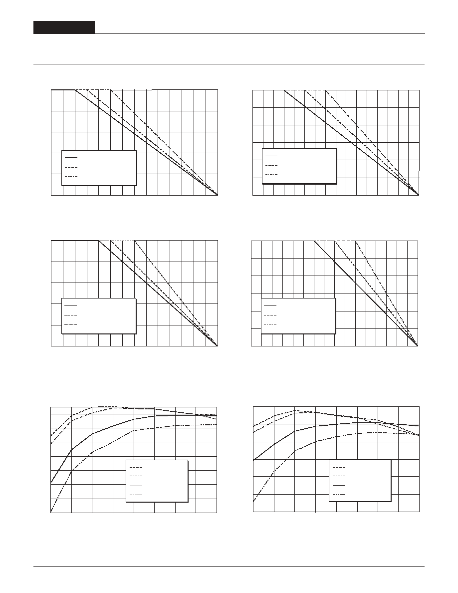
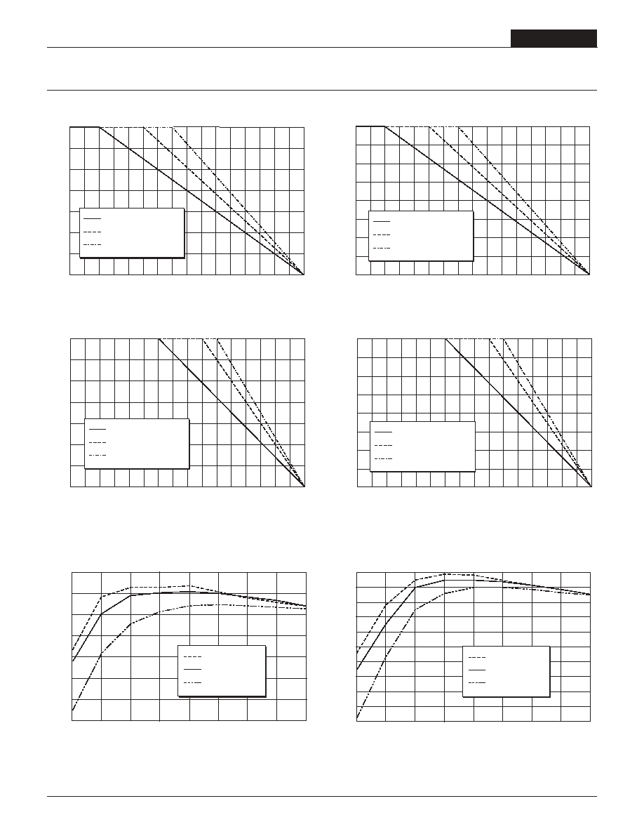
Figure 2a. Temperature Derating Without Heat Sink
Figure 2b. Temperature Derating With Heat Sink
Figure 2c. Effi ciency vs. Output Current and Input Voltage
Figure 3a. Temperature Derating Without Heat Sink
Figure 3b. Temperature Derating With Heat Sink
Figure 3c. Effi ciency vs. Output Current and Input Voltage
Temperature Derating and Electrical Performance Curves
Q48 Models (30 Watts)
Q12 Models (25 Watts)
Model UPB-5/6-Q48
Model UPB-5/5-Q12
UPB Models
2 5 - 4 0 W , S I N G L E O U T P U T D C / D C C O N V E R T E R S
5
Ou
t
p
u
t
Po
we
r
(
W
a
t
t
s
)
Ambient Temperature (°C)
35
30
25
20
15
10
5
0
25
0 30 35 40 45 50 55 60 65 70 75 80 85 90 95 100
Natural Convection Cooling
150 Linear Feet Per Minute
300 Linear Feet Per Minute
O
u
tp
u
t
P
o
w
e
r (W
a
t
ts
)
Ambient Temperature (°C)
35
30
25
20
15
10
5
0
25
0 30 35 40 45 50 55 60 65 70 75 80 85 90 95 100
Natural Convection Cooling
150 Linear Feet Per Minute
300 Linear Feet Per Minute
40
35
30
25
20
15
10
5
0
O
u
tp
u
t
P
o
w
e
r (W
a
t
ts
)
Ambient Temperature (°C)
25
0 30 35 40 45 50 55 60 65 70 75 80 85 90 95 100
Natural Convection Cooling
150 Linear Feet Per Minute
300 Linear Feet Per Minute
E
f
ficiency (
%
)
Output Current (Amps)
0.5
1
2
3
4
5
6
7
8
88
86
84
82
80
78
76
74
72
70
68
Efficiency @ 36V
IN
Efficiency @ 48V
IN
Efficiency @ 72V
IN
Figure 4a. Temperature Derating Without Heat Sink
Figure 4b. Temperature Derating With Heat Sink
Figure 4c. Effi ciency vs. Output Current and Input Voltage
Figure 5a. Temperature Derating Without Heat Sink
Figure 5b. Temperature Derating With Heat Sink
Figure 5c. Effi ciency vs. Output Current and Input Voltage
Temperature Derating and Electrical Performance Curves
Model UPB-5/8-D48
Model UPB-5/7-D24
D48 Models (40 Watts)
D24 Models (35 Watts)
Efficiency (%)
Output Current (Amps)
0.77
1.56 2.33 3.11 3.89 4.67 5.44 6.22 7
88
86
84
82
80
78
76
74
Efficiency @ 18V
IN
Efficiency @ 24V
IN
Efficiency @ 36V
IN
O
u
tp
u
t
P
o
w
e
r (W
a
t
ts
)
Ambient Temperature (°C)
40
35
30
25
20
15
10
5
0
25
0 30 35 40 45 50 55 60 65 70 75 80 85 90 95 100
Natural Convection Cooling
150 Linear Feet Per Minute
300 Linear Feet Per Minute
2 5 - 4 0 W , S I N G L E O U T P U T D C / D C C O N V E R T E R S
XPB Series
6
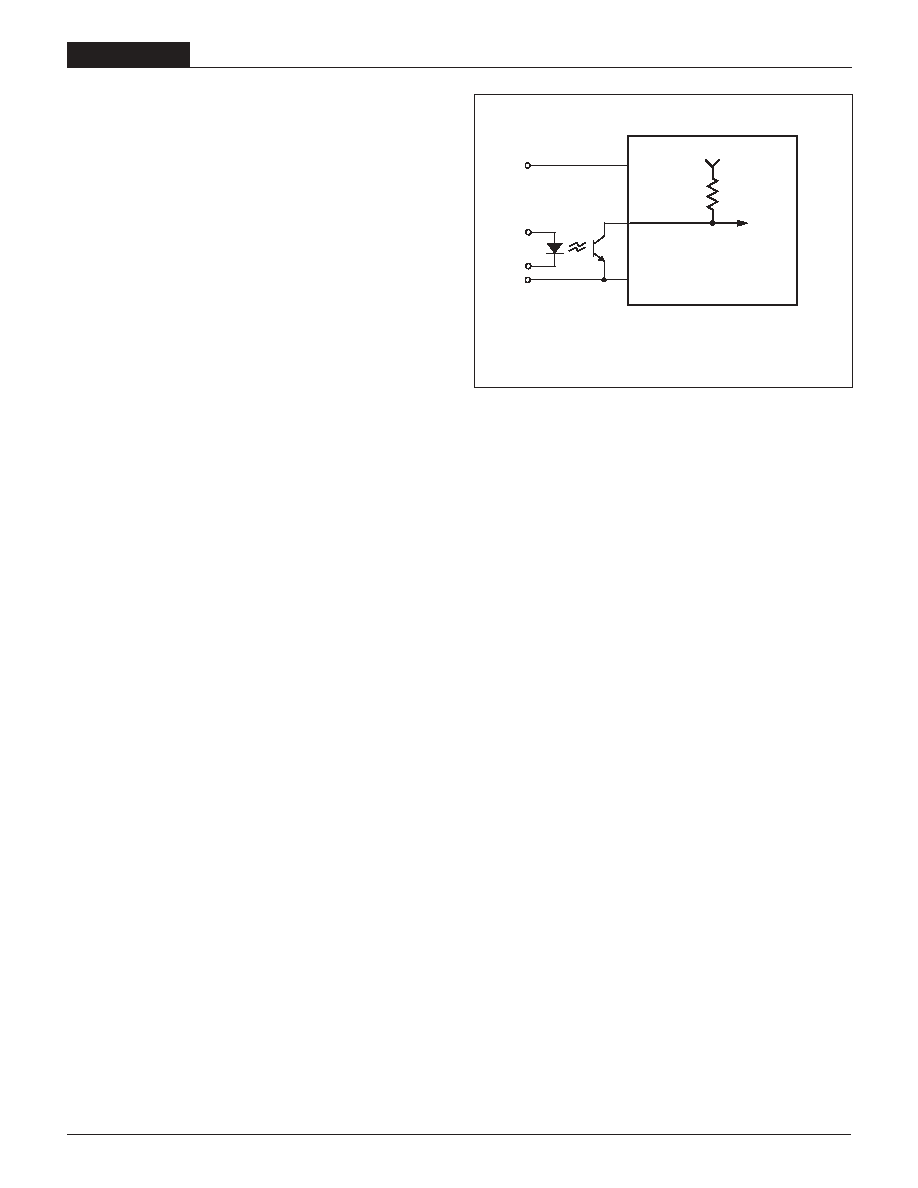
Figure 6. Driving the On/Off Control Pin
Case Connection
Unlike most other DC/DC converters, UPB DC/DC's do not have their metal
case connected to one of their input pins. The "uncommitted" case is con-
nected to pin 4 which, depending on your system confi guration, should be
connected to either +Input (pin 3), Input (pin 2), Common (pin 8), or earth
ground.
On/Off Control (Standard)
The On/Off Control pin (pin 5) may be used for remote on/off operation. As
shown in Figure 6, the control pin has an internal 10k
pull-up resistor to
approximately 10V. The converter is designed so that it is enabled when the
control pin is left open (normal mode) and disabled when the control pin is
pulled low (to less than +0.8V relative to Input, pin 2).
Dynamic control of the on/off function is best accomplished with a mechani-
cal relay or an open-collector/open-drain drive circuit (optically isolated if
appropriate). The drive circuit should obviously be able to sink approximately
1mA when activated and withstand more than 10 Volts when deactivated.
Applying an external voltage to pin 5 when no input power is applied to the
converter can cause permanent damage to the converter. The on/off control
function, however, is designed such that the converter can be disabled (pin
5 pulled low) while input power is ramping up and then "released" once the
input has stabilized. Under these circumstances, it takes approximately 30ms
for the output of the fully loaded DC/DC to ramp up and settle to within ±1%
of its fi nal value after the converter has been turned on.
Synchronization (Optional)
In critical applications employing multiple switching DC/DC converters, it may
be desirable to intentionally synchronize the switching of selected converters
(so the system noise can be reduced with notch fi ltering) or to purposely
desynchronize the converters (to lessen the current-carrying requirements on
intermediate dc buses). UPB DC/DC Converters have been designed so that
the On/Off Control function on pin 5 can be replaced with a Sync function.
This change has to be implemented by DATEL during the product assembly
process. Contact our Applications Engineering Group for additional details.
To synchronize the switching of multiple UPB converters confi gured with the
Sync function, an external clock can be applied to pin 5 of each converter.
The clock should be a TTL square wave referenced to Input (logic high =
+2 to +5 Volts, 250µA max.; logic low = 0 to +0.8 Volts, 70µA max.) with a
maximum 1µsec "high" duration. The frequency of the synchronizing clock
should be higher than that of any individual converter. Therefore, it should
be 185kHz ±5kHz.
Output Trimming
V
OUT
may be trimmed ±5% via a single trimpot or fi xed resistor. The trimpot
should be connected between +Output (pin 9) and Common (pin 8) with its
wiper connected to pin 10 (Trim). A trimpot can also be used to determine the
value of a single fi xed resistor which can be connected between pin 10 (Trim)
and pin 9 (+Output) to trim "down" the output voltages, or between pins 10
(Trim) and 6 (Output) to trim "up" the output voltages. Fixed resistors should
be metal-fi lm types with absolute TCR's less than 100ppm/°C to ensure
stability.
3
2
5
+INPUT
INPUT
+10V
10k
9
ON/OFF
CONTROL
UPB Models
2 5 - 4 0 W , S I N G L E O U T P U T D C / D C C O N V E R T E R S
7
DATEL's world-class design, development and manufacturing team stands
ready to work with you to deliver the exact power converter you need for your
demanding, large volume, OEM applications. More importantly . . . we'll do
it on time and within budget!
Our experienced applications and design staffs; quick-turn prototype capabil-
ity; highly automated, SMT assembly facilities; and in-line SPC quality-control
techniques combine to give us the unique ability to design and deliver any
quantity of power converters to the highest standards of quality and reliability.
We have compiled a large library of DC/DC designs that are currently used
in a variety of telecom, medical, computer, railway, aerospace and industrial
applications. We may already have the converter you need.
Contact us. Our goal is to provide you the highest-quality, most cost-effective
power converters available.
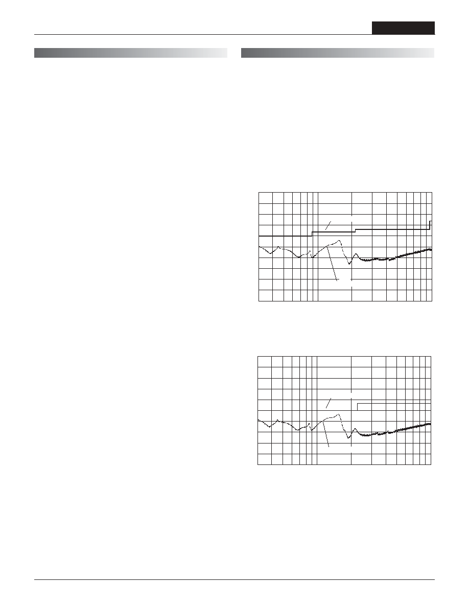
If you're designing with EMC in mind, please note that all of DATEL's UPB
25-40 Watt DC/DC Converters have been characterized for radiated and
conducted emissions in our new EMI/EMC laboratory. Testing is conducted in
an EMCO 5305 GTEM test cell utilizing EMCO automated EMC test software.
Radiated emissions are tested to the limits of FCC Part 15, Class B and
CISPR 22 (EN 55022), Class B. Correlation to other specifi cations can be
supplied upon request. Radiated emissions plots to FCC and CISPR 22 for
model UPB-5/8-D48 appear below. Published EMC test reports are available
for each model number. Contact DATEL's Applications Engineering Depart-
ment for more details.
80
70
60
50
40
30
20
10
0
10
20
Frequency (MHz)
100
1000
FCC Class B Limit
UPB-5/8-D48 Radiated Emissions
FCC Part 15 Class B, 3 Meters
Converter Output = +5Vdc @ +6.45 Amps
R
a
d
i
ated
E
m
i
s
si
on
s (dB
µ
V
/
M
)
Radiated Emissions
UPB-5/8-D48 Radiated Emissions
EN 55022 Class B, 10 Meters
Converter Output = +5Vdc @ +6.45 Amps
80
70
60
50
40
30
20
10
0
10
20
Frequency (MHz)
100
1000
Radiated Emissions
EN 55022 Class B Limit
R
a
d
i
ated
E
m
i
s
si
on
s (dB
µ
V
/
M
)
C U S T O M C A P A B I L I T I E S
E M I R A D I A T E D E M I S S I O N S
DS-0392 4/01
Quality and Reliability
The UPB Models are the latest DC/DC Converters to emerge from DATEL's
new, company-wide approach to designing and manufacturing the most reli-
able power converters available. The fi ve-pronged program draws our Qual-
ity Assurance function into all aspects of new-product design, development,
characterization, qualifi cation and manufacturing.
Design for Reliability
Design for Reliability is woven throughout our multi-phased, new-product-
development process. Design-for-reliability practices are fully documented
and begin early in the new-product development cycle with the following goals:
1. To work from an approved components/vendors list ensuring the use of
reliable components and the rigorous qualifi cation of new components.
2. To design with safety margins by adhering to a strict set of derating
guidelines and performing theoretical worst-case analyses.
3. To locate potential design weaknesses early in the product-development
cycle by using extensive HALT (Highly Accelerated Life Testing).
4. To prove that early design improvements are effective by employing a
thorough FRACA (Failure Reporting Analysis and Corrective Action) system.
HALT Testing
The goal of the accelerated-stress techniques used by DATEL is to force
device maturity, in a short period of time, by exposing devices to excessive
levels of "every stimulus of potential value." We use HALT (Highly Acceler-
ated Life Testing) repeatedly during the design and early manufacturing
phases to detect potential electrical and mechanical design weaknesses
that could result in possible future fi eld failures.
During HALT, prototype and pre-production DC/DC converters are subjected
to progressively higher stress levels induced by thermal cycling, rate of
temperature change, vibration, power cycling, product-specifi c stresses (such
as dc voltage variation) and combined environments. The stresses are not
meant to simulate fi eld environments but to expose any weaknesses in a
product's electro/mechanical design and/or assembly processes. The goal of
HALT is to make products fail so that device weaknesses can be analyzed
and strengthened as appropriate. Applied stresses are continually stepped
up until products eventually fail. After corrective actions and/or design
changes, stresses are stepped up again and the cycle is repeated until the
"fundamental limit of the technology" is determined.
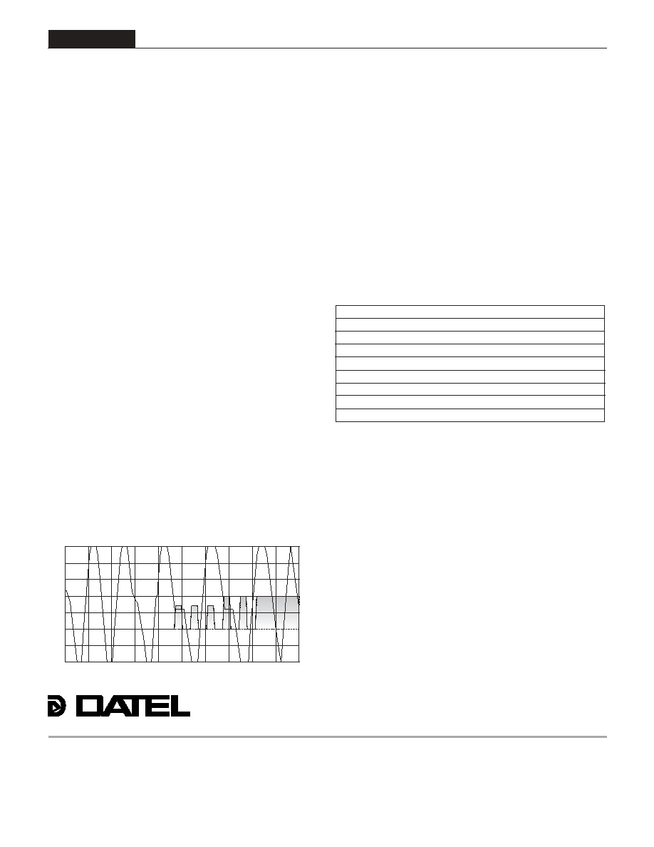
DATEL has invested in a Qualmark OVS-1 HALT tester capable of applying
voltage and temperature extremes as well as 6-axis, linear and rotational,
random vibration. A typical HALT profi le (shown above) consists of thermal
cycling (55 to +125°C, 30°C/minute) and simultaneous, gradually increas-
ing, random longitudinal and rotational vibration up to 20G's with load cycling
and applied-voltage extremes added as desired. Many devices in DATEL's
new A-Series could not be made to fail prior to reaching either the limits of
the HALT chamber or some previously known physical limit of the device. We
also use the HALT chamber and its ability to rapidly cool devices to verify
their "cold-start" capabilities.
Qualifi cation
For each new product, electrical performance is verifi ed via a comprehensive
characterization process and long-term reliability is confi rmed via a rigorous
qualifi cation procedure. The qual procedure includes such strenuous tests
as thermal shock and 500 hour life. Qual testing is summarized below.
In-Line Process Controls and Screening
A combination of statistical sampling and 100% inspection techniques keeps
our assembly line under constant control. Parameters such as solder-paste
thickness, component placement, cleanliness, etc. are statistically sampled,
charted and fi ne tuned as necessary. Visual inspections are performed by
trained operators after pick-and-place, soldering and cleaning operations.
Units are 100% electrically tested prior to potting. All devices are temperature
cycled, burned-in, hi-pot tested and fi nal-electrical tested prior to external
visual examination, packing and shipping.
Rapid Response to Problems
DATEL employs an outstanding corrective-action system to immediately
address any detected shortcomings in either products or processes. When-
ever our assembly, quality or engineering personnel spot a product/process
problem, or if a product is returned with a potential defect, we immediately
perform a detailed failure analysis and, if necessary, undertake corrective
actions. Over time, this system has helped refi ne our assembly operation to
yield one of the lowest product defect rates in the industry.
Typical HALT Profi le
Qualifi cation Test Method/Comments
HALT DATEL in-house procedure
High Temperature Storage Max. rated temp., 1,000 hours
Thermal Shock 10 cycles, 55 to +125°C
Temperature/Humidity +85°C, 85% humidity, 48 hours
Lead Integrity DATEL in-house procedure
Life Test +70°C, 500 hours*
Marking Permanency DATEL in-house procedure
End Point Electrical Tests Per product specifi cation
Qualifi cation Testing
* Interim electrical test at 200 hours.
10 20 30 40 50 60 70 80 90
40
20
0
Random
Vi
br
at
i
o
n
(
G'
s
)
Tem
p
er
at
ure (
°
C)
Test Time (minutes)
100
80
60
40
20
0
20
40
2 5 - 4 0 W , S I N G L E O U T P U T D C / D C C O N V E R T E R S
XPB Series
8
DATEL makes no representation that the use of its products in the circuits described herein, or the use of other technical information contained herein, will not infringe upon existing or future patent rights. The descriptions contained herein do
not imply the granting of licenses to make, use, or sell equipment constructed in accordance therewith. Specifi cations are subject to change without notice. The DATEL logo is a registered DATEL, Inc. trademark.
DATEL (UK) LTD. Tadley, England Tel: (01256)-880444
DATEL S.A.R.L. Montigny Le Bretonneux, France Tel: 01-34-60-01-01
DATEL GmbH München, Germany Tel: 89-544334-0
DATEL KK Tokyo, Japan Tel: 3-3779-1031, Osaka Tel: 6-6354-2025
DATEL, Inc. 11 Cabot Boulevard, Mansfi eld, MA 02048-1151
Tel: (508) 339-3000 (800) 233-2765 Fax: (508) 339-6356
Internet: www.datel.com Email: sales@datel.com
Data Sheet Fax Back: (508) 261-2857
INNOVATION and EX C ELL E N C E
®
®
ISO-9001 REGISTERED