
DATEL, Inc., Mansfield, MA 02048 (USA)
∑
Tel: (508)339-3000, (800)233-2765 Fax: (508)339-6356
∑
Email: sales@datel.com
∑
Internet: www.datel.com
Single Output
UST Models
Features
Figure 1. Simplified Schematic
Low-Cost, High-Reliability
3 Watt, DC/DC Converters
Rarely, has a Series of low-power DC/DC converters been defined by both low
cost and DATEL's made-in-the-USA quality and reliability. Our new UST Series of
single-output DC/DC's achieves this best-of-both-worlds status by implementing a
proven circuit architecture (170-200kHz flyback design) as a full, SMT-on-pcb
assembly (including surface-mount magnetics) that is truly 100% automatically
assembled. Packaged in miniature 1.25" x 0.8", DIP-like plastic packages (UL94V-0
rated) and requiring no external components, UST Series DC/DC's bring true
component-like convenience to designers of today's distributed power systems.
Output voltages are 5, 12 or 15 Volts. Input voltage ranges are 4.5-9V ("D5"
models), 9-18V ("D12" models) or an ultra-wide 18-72V ("D48" models). UST
DC/DC's are fully isolated (1000Vdc guaranteed) and include input (pi type) and
output filters within their package. Output transient response is a quick 200µsec,
while output ripple and noise are typically 75mVp-p.
These rugged modules are fully encapsulated with a thermally conductive
potting compound that contributes to their outstanding moisture/vibration resistance
and impressive MTBF. They operate over the full ≠40 to +75∞C temperature range
without derating. All models have been thoroughly characterized (electrically,
mechanically and thermally), qualified (including HALT), and EMI/EMC tested.
Additionally, they are certified to UL1950, CSA 22.2 No. 950 and IEC950.
DATEL's UST Model 3W DC/DC's are excellent selections for telecom/datacom,
computer and process-control applications demanding small size, low cost and high
reliability. If required, their design "flexibility" allows for easy modification to your
application-specific requirements.
+V
OUT
+V
IN
≠V
IN
PWM
CONTROLLER
OPTO
ISOLATION
REFERENCE &
ERROR AMP
COMMON
INNOVATION and EX C ELL E N C E
Æ
Æ
Lowest cost! Highest reliability!
100% SMT-on-pcb, including magnetics
100% automatically assembled
Standard "DIP" package and pinouts
Fully isolated, 1000Vdc guaranteed
5, 12 or 15 Volt outputs
Choice of 3 wide-range inputs:
4.5-9 Volts
9-18 Volts
18-72 Volts
Guaranteed efficiencies to 73%
≠40 to +75∞C full-power operation
Internal input/output filtering
UL1950/C22.2 No. 950/IEC950 certified
Modifications and customs for OEM's

XST Series
3 W , S I N G L E O U T P U T D C / D C C O N V E R T E R S
0.020 ±0.002 DIA.
(0.508 ±0.051)
0.15 MIN
(3.81)
0.45
(11.43)
1.25
(31.75)
0.200
(5.08)
0.10
(2.54)
0.80
(20.32)
0.600
(15.24)
0.100
(2.54)
0.18
(4.57)
STANDOFFS
0.025
(0.64)
0.600
(15.24)
BOTTOM VIEW
1 2
3 4
5
6
8
7
PLASTIC CASE WITH AN INSULATED BASE
UST-5/500-D5
5
500
75
120
±0.2%
±0.5%
5
4.5-9
18/676
72%
74%
C1, P1
UST-5/500-D12
5
500
75
120
±0.2%
±0.5%
12
9-18
25/282
70%
74%
C1, P1
UST-5/500-D48
5
500
75
120
±0.2%
±0.5%
48
18-72
7/69
71%
75%
C1, P1
UST-12/250-D5
12
250
75
150
±0.5%
±0.5%
5
4.5-9
30/800
73%
75%
C1, P1
UST-12/250-D12
12
250
75
150
±0.5%
±0.5%
12
9-18
25/338
72%
74%
C1, P1
UST-12/250-D48
12
250
75
150
±0.5%
±0.5%
48
18-72
8/81
73%
77%
C1, P1
UST-15/200-D5
15
200
75
150
±0.5%
±0.5%
5
4.5-9
30/800
73%
75%
C1, P1
UST-15/200-D12
15
200
75
150
±0.5%
±0.5%
12
9-18
25/333
73%
75%
C1, P1
UST-15/200-D48
15
200
75
150
±0.5%
±0.5%
48
18-72
8/81
73%
77%
C1, P1
2
P A R T N U M B E R S T R U C T U R E
M E C H A N I C A L S P E C I F I C A T I O N S
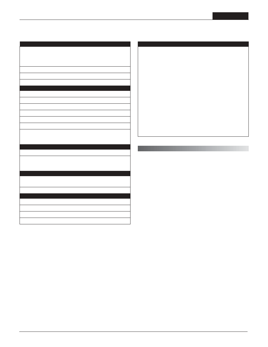
Performance Specifications and Ordering Guide
R/N (mVp-p)
Load
V
OUT
(Volts)
Output
Package
(Case,
Pinout)
Efficiency
Regulation (Max.)
Line
V
IN
Nom.
(Volts)
Range
(Volts)
Model
Input
I
IN
(mA)
Max.
Typ.
Typ.
Min.
I
OUT
(mA, Max.)
Typical at T
A
= +25∞C under nominal line voltage and full-load conditions unless otherwise noted.
Ripple/Noise (R/N) measured over a 20MHz bandwidth.
10% to 100% load.
Nominal line voltage, no-load/full-load conditions.
Input Voltage Range:
D5 = 4.5-9 Volts (5V nominal)
D12 = 9-18 Volts (12V nominal)
D48 = 18-72 Volts (48V nominal)
Nominal Output Voltage:
5, 12 or 15 Volts
Maximum Output Current
in mA
Product Series
Output Configuration:
U = Unipolar
5
U ST
500
D48
-
/
-
Case C1
Pin
1
2
3
4
5
6
7
8
I/O Connectiions
Function P1
+Input
+Input
≠Input
≠Input
Common
+Output
Common
+Output
Output P
o
wer (W
atts)
Ambient Temperature (
∞
C)
≠40
0
15
20
25
30
35
40
45
50
55
60
65
70
75
80
85
90
95 100
3.5
3
2.5
2
1.5
1
0.5
0
Output Power vs. Ambient Temperature
V
IN
Nominal, Natural Convection
T E M P E R A T U R E D E R A T I N G
UST Models
3 W , S I N G L E O U T P U T D C / D C C O N V E R T E R S
3
Input Voltage:
"D5" Models
12 Volts
"D12" Models
20 Volts
"D48" Models
80 Volts
Input Reverse-Polarity Protection
Current must be <2A. Brief duration
only. Fusing recommended.
Output Overvoltage Protection
None
Output Current
Current limited. Max. current and
short-circuit duration are model
dependent. "D12" and "D48" models
can withstand sustained output short
circuits.
Storage Temperature
≠40 to +100∞C
Lead Temperature (soldering, 10 sec.)
+300∞C
Floating Outputs
Since these are isolated DC/DC converters, their outputs are "floating."
Users may ground either the Common (pins 5 and 7) for normal usage or
the positive side (+Output, pins 6 and 8) to effectively reverse the output
polarity.
Filtering and Noise Reduction
All UST 3 Watt DC/DC Converters achieve their rated ripple and noise
specifications without the use of external input/output capacitors. In critical
applications, input/output ripple and noise may be further reduced by
installing electrolytic capacitors across the input terminals and/or low-ESR
tantalum or electrolytic capacitors across the output terminals. The caps
should be located as close to the power converters as possible. Typical
values are listed in the tables below. In many applications, using values
greater than those listed will yield better results.
To Reduce Input Ripple
"D5" Models
47µF, 15V
"D12" Models
10µF, 35V
"D48" Models
4.7µF, 100V
To Reduce Output Ripple
5V Outputs
47µF, 10V, Low ESR
12/15V Outputs
22µF, 20V, Low ESR
In critical, space-sensitive applications, DATEL may be able to tailor the
internal input/output filtering of these units to meet your specific require-
ments. Contact our Applications Engineering Group for additional details.
These are stress ratings. Exposure of devices to any of these conditions may adversely
affect long-term reliability. Proper operation under conditions other than those listed in the
Performance/Functional Specifications Table is not implied.
Absolute Maximum Ratings
T E C H N I C A L N O T E S
Performance/Functional Specifications
Typical @ T
A
= +25∞C under nominal line voltage and full-load conditions, unless noted.
Input
Input Voltage Range:
"D5" Models
4.5-9 Volts (5V nominal)
"D12" Models
9-18 Volts (12V nominal)
"D48" Models
18-72 Volts (48V nominal)
Input Current
See Ordering Guide
Input Filter Type
Pi
Reverse-Polarity Protection
Yes (Instantaneous, 2A maximum)
Output
V
OUT
Accuracy (50% load)
±1%, maximum
Temperature Coefficient
±0.02% per ∞C
Ripple/Noise (20MHz BW)
See Ordering Guide
Line/Load Regulation
See Ordering Guide
Efficiency
See Ordering Guide
Isolation Voltage
1000Vdc, minimum
Current Limiting:
"D5" Models
Power-limiting technique, auto-recovery
"D12" and "D48" Models
Hiccup technique, auto-recovery
Dynamic Characteristics
Transient Response (50% load step)
200µsec to ±1.5% of final value
Switching Frequency:
"D48" Models
200kHz
"D5" and "D12" Models
170kHz
Environmental
Operating Temperature
(Ambient, no derating)
≠40 to +75∞C
Storage Temperature
≠40 to +100∞C
Physical
Dimensions
1.25" x 0.8" x 0.45" (31.8 x 20.3 x 11.4mm)
Case Material
Diallyl phthalate, UL94V-0-rated
Pin Material
Brass, solder coated
Weight
0.5 ounces (14.2 grams)
These power converters require a minimum 10% loading to maintain specified regulation.
Operation under no-load conditions will not damage these devices; however
they may not meet all listed specifications.
Application-specific internal input/output filtering can be recommended and perhaps added
internally upon request. Contact DATEL Applications Engineering for details.
Devices can be screened or modified for higher guaranteed isolation voltages.
Contact DATEL Applications Engineering for details.
XST Series
3 W , S I N G L E O U T P U T D C / D C C O N V E R T E R S
Input Fusing
Certain applications and/or safety agencies may require the installation of
fuses at the inputs of power conversion components. For DATEL UST 3
Watt DC/DC Converters, you should use slow-blow type fuses with values
no greater than the following:
V
IN
Range
Fuse Value
"D5"
1.5A
"D12"
1A
"D48"
0.5A
DATEL makes no representation that the use of its products in the circuits described herein, or the use of other technical information contained herein, will not infringe upon existing or future patent rights. The descriptions contained herein
do not imply the granting of licenses to make, use, or sell equipment constructed in accordance therewith. Specifications are subject to change without notice. The DATEL logo is a registered DATEL, Inc. trademark.
DATEL (UK) LTD. Tadley, England Tel: (01256)-880444
DATEL S.A.R.L. Montigny Le Bretonneux, France Tel: 01-34-60-01-01
DATEL GmbH M¸nchen, Germany Tel: 89-544334-0
DATEL KK Tokyo, Japan Tel: 3-3779-1031, Osaka Tel: 6-6354-2025
DATEL, Inc. 11 Cabot Boulevard, Mansfield, MA 02048-1151
Tel: (508) 339-3000 (800) 233-2765 Fax: (508) 339-6356
Internet: www.datel.com Email: sales@datel.com
Data Sheet Fax Back: (508) 261-2857
DS-0444 6/01
INNOVATION and EX C ELL E N C E
Æ
Æ
DATEL's world-class design, development and manufacturing team stands
ready to work with you to deliver the exact power converter you need for
your demanding, large volume, OEM applications. And ... we'll do it on time
and within budget!
Our experienced applications and design staffs; quick-turn prototype
capability; highly automated, SMT assembly facilities; and in-line SPC
quality-control techniques combine to give us the unique ability to design
and deliver any quantity of power converters to the highest standards of
quality and reliability.
We have compiled a large library of DC/DC designs that are currently used
in a variety of telecom, medical, computer, railway, aerospace and industrial
applications. We may already have the converter you need.
Contact us. Our goal is to provide you the highest-quality, most cost-
effective power converters available.
C U S T O M C A P A B I L I T I E S
ISO 9001 REGISTERED
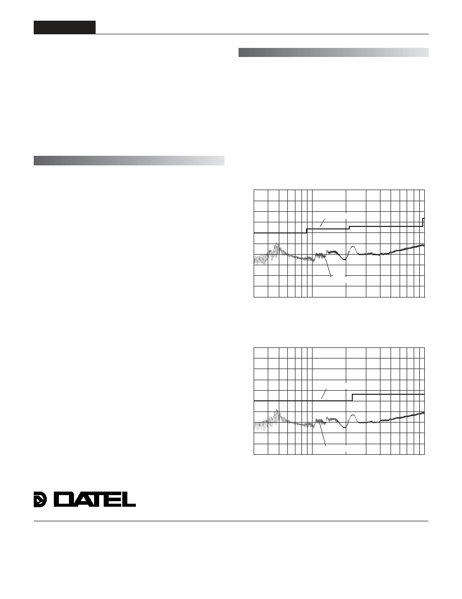
If you're designing with EMC in mind, please note that all of DATEL's
UST 3 Watt DC/DC Converters have been characterized for radiated and
conducted emissions in our new EMI/EMC laboratory. Testing is conducted
in an EMCO 5305 GTEM test cell utilizing EMCO automated EMC test
software. Radiated emissions are tested to the limits of FCC Part 15, Class
B and CISPR 22 (EN 55022), Class B. Correlation to other specifications
can be supplied upon request. Radiated emissions plots to FCC and CISPR
22 for model UST-5/500-D48 appear below. Published EMC test reports are
available for each model number. Contact DATEL's Applications Engineering
Department for more details.
E M I R A D I A T E D E M I S S I O N S
U S T - 5 / 5 0 0 - D 4 8 R a d i a t e d E m i s s i o n s
E N 5 5 0 2 2 C l a s s B , 1 0 M e t e r s
C o n v e r t e r O u t p u t = + 5 V d c @ + 4 5 0 m A
8 0
7 0
6 0
5 0
4 0
3 0
2 0
1 0
0
1 0
2 0
F r e q u e n c y ( M H z )
1 0 0
1 0 0 0
R a d i a t e d E m i s s i o n s
E N 5 5 0 2 2 C l a s s B L i m i t
R
a
d
i
a
t
e
d
E
m
i
s
s
i
o
n
s
(
d
B
µ
V
/
M
)
8 0
7 0
6 0
5 0
4 0
3 0
2 0
1 0
0
1 0
2 0
F r e q u e n c y ( M H z )
1 0 0
1 0 0 0
F C C C l a s s B L i m i t
U S T - 5 / 5 0 0 - D 4 8 R a d i a t e d E m i s s i o n s
F C C P a r t 1 5 C l a s s B , 3 M e t e r s
C o n v e r t e r O u t p u t = + 5 V d c @ + 4 5 0 m A
R
a
d
i
a
t
e
d
E
m
i
s
s
i
o
n
s
(
d
B
µ
V
/
M
)
R a d i a t e d E m i s s i o n s