≠OUTPUT
(7)
+INPUT
(1)
≠INPUT
(2)
PWM
CONTROLLER
REFERENCE &
ERROR AMP
THERMAL
SHUTDOWN
OPTO
ISOLATION
UVLO & OVLO
COMPARATORS
ON/OFF
CONTROL
(4)
V
OUT
TRIM
(8)
+OUTPUT
(6)
SWITCH
CONTROL
Single Output
A-Series, UWR Models
Features
High-Density, 3.3V
OUT
and 5V
OUT
26-40 Watt DC/DC Converters
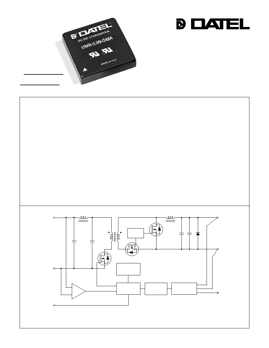
Figure 1. Simplifi ed Schematic
The newest products in DATEL's fl agship A-Series are the UWR, 26-40 Watt
isolated singles. Housed in standard 2" x 2" metal packages (which have traditionally
carried 15-20 Watt devices), these power converters supply up to 9 Amps @ 3.3V
or 8 Amps at 5V. They exemplify DATEL's relentless drive to bring designers more
power/current, in standard packages/pinouts, without compromising reliability or
resorting to thermal specmanship. Input voltage ranges are 10-18V ("D12" models),
18-36V ("D24" models) or 36-75V ("D48") models.
Employing an advanced, fully synchronous, high-frequency (300-360kHz) for-
ward topology, UWR 26-40W singles attain 88-90% effi ciencies enabling full-power
operation to ambient temperatures as high as +55∞C without supplemental air fl ow.
Assembled using fully automated, SMT-on-pcb techniques, these DC/DC's addition-
ally provide low noise (75mVp-p), high accuracy (±1%), tight line/load regulation
(±0.5%), quick step response (200µsec), and stable no-load operation.
All models feature input pi fi lters, input undervoltage and overvoltage shutdown,
output overvoltage protection, current limiting, short-circuit protection, and thermal
shutdown. Each model has a V
OUT
trim pin as well as an on/off control function that
may be ordered with either positive or negative polarity. These devices are fully iso-
lated (1500Vdc) and satisfy UL/EN/IEC60950 safety requirements for FUNCTIONAL
insulation. "D48" models (36-75V inputs) are CE marked.
INNOVATION and EX C ELL E N C E
Æ
Æ
DATEL, Inc., Mansfi eld, MA 02048 (USA)
∑ Tel: (508)339-3000, (800)233-2765 Fax: (508)339-6356 ∑ Email: sales@datel.com ∑ Internet: www.datel.com
Standard 2" x 2" packages/pinouts
Output voltages/currents:
∑
3.3 Volts @ 8/9 Amps
∑
5 Volts @ 7/8 Amps
Choice of 3 input voltage ranges:
10-18V, 18-36V, 36-75V
Fully synchronous forward topology
Outstanding performance:
∑
±1% setpoint accuracy
∑
Effi ciencies to 90%
∑
Noise as low as 75mVp-p
∑
Stable no-load operation
On/off control and V
OUT
trim pins
Fully isolated (1500Vdc); I/O protected
Qual/HALT/EMI tested; Thermal shutdown
UL/EN/IEC60950 certifi ed; CE marked
!
!
!
!
!
!
!
!
!
A - S E R I E S
A Series
2 6 - 4 0 W , S I N G L E O U T P U T D C / D C C O N V E R T E R S
R/N (mVp-p) Regulation
(Max.)
Effi ciency
Package
V
OUT
I
OUT
V
IN
Nom.
Range
I
IN
(Case,
Model
(Volts) (Amps)
Typ. Max.
Line Load
(Volts) (Volts) (mA/A) Min. Typ. Pinout)
2
Performance Specifi cations and Ordering Guide
Typical at T
A
= +25∞C under nominal line voltage and full-load conditions, unless noted.
Ripple/Noise (R/N) is tested/speciifed over a 20MHz bandwidth. All models are specifi ed with
an external 0.47µF multi-layer ceramic capacitor installed across their output pins.
Load regulation is specifi ed over 0-100% load conditions. All models are stable and regulate
within spec under no-load conditions, with perhaps a slight increase in output ripple/noise.
Nominal line voltage, no-load/full-load conditions.
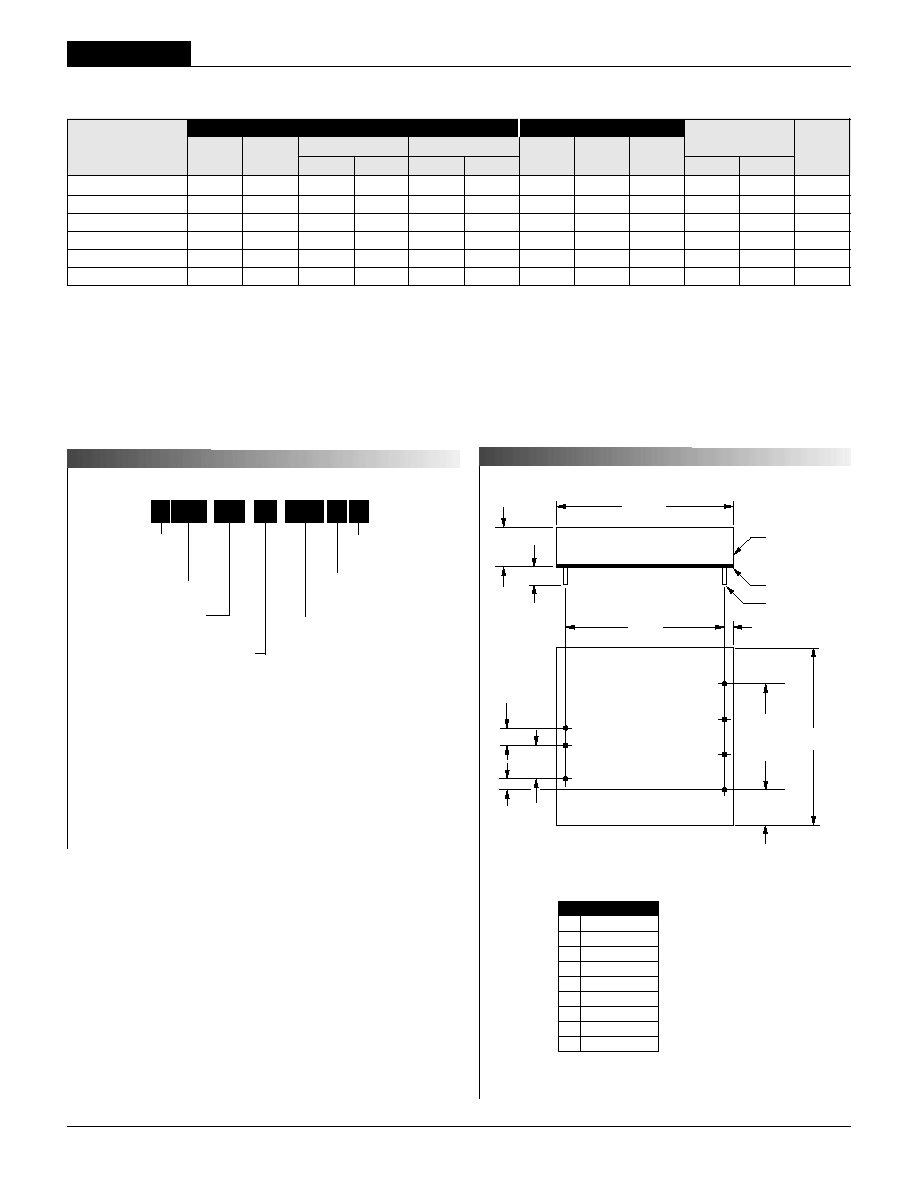
UWR-3.3/8-D12A 3.3 8 75 110 ±0.5% ±0.5% 12 10-18 145/2.51 85% 87.5% C4, P6
UWR-3.3/9-D24A 3.3 9 75 110 ±0.5% ±0.5% 24 18-36 50/1.4 86% 88.5% C4, P6
UWR-3.3/9-D48A 3.3 9 75 110 ±0.5% ±0.5% 48 36-75 25/0.7 86% 88.5% C4, P6
UWR-5/7-D12A 5 7 75 110 ±0.5% ±0.5% 12 10-18 160/3.26 85.5% 89.5% C4, P6
UWR-5/8-D24A 5 8 75 110 ±0.5% ±0.5% 24 18-36 70/1.85 86% 90% C4, P6
UWR-5/8-D48A 5 8 75 110 ±0.5% ±0.5% 48 36-75 25/0.93 86% 90% C4, P6
Wide Range Input
Output Confi guration:
U = Unipolar
Nominal Output Voltage:
3.3 or 5 Volts
Maximum Output Current
in Amps
Input Voltage Range:
D12 = 10-18 Volts (12V nominal)
D24 = 18-36 Volts (24V nominal)
D48 = 36-75 Volts (48V nominal)
U WR
9
-
/
D48
-
3.3
Part Number Suffi xes
Note
For D12A and D24A models,
the case is connected to
Pin 2 (≠Input).
For D48A models, the case is
connected to Pin 1 (+Input).
A
Output
Input
P A R T N U M B E R S T R U C T U R E
M E C H A N I C A L S P E C I F I C A T I O N S
Pin Function
P6
1
+Input
2
≠Input
3
No
Pin
4 On/Off
Control
5
No
Pin
6
+Output
7
≠Output
8
Trim
I/O Connections
UWR 26-40W DC/DC's are designed so the On/Off Control function
on pin 4 can be ordered with either positive (open or "high" = on)
or negative (open = off, pull low = on) polarity. The standard part
number with no suffi x denotes positive polarity. Add an "N" suffi x
to select negative polarity.
No Suffi x On/Off Control function (positive polarity) on pin 4.
"N" Suffi x On/Off Control function (negative polarity) on pin 4.
N
BOTTOM VIEW
1.800
(45.72)
0.10
(2.54)
2.00
(50.80)
8
5
6
7
0.40
(10.16)
0.200
(5.08)
0.400
(10.16)
0.100
(2.54)
1
2
4
METAL CASE
INSULATED BASE
0.040 ±0.002 DIA.
(1.016 ±0.051)
2.00
(50.80)
0.20 MIN
(5.08)
0.45
(11.43)
1.200
(30.48)
3 EQ. SP. @
0.400 (10.16)
DIMENSIONS ARE IN INCHES (MM)
Case C4
Add "N" suffi x
as desired
A-Series
High Reliability
UWR Models
2 6 - 4 0 W , S I N G L E O U T P U T D C / D C C O N V E R T E R S
3
Performance/Functional Specifi cations
Typical @ T
A
= +25∞C under nominal line voltage and full-load conditions, unless noted.
Input
Input Voltage Range:
D12 Models 10-18 Volts (12V nominal)
D24 Models 18-36 Volts (24V nominal)
D48 Models 36-75 Volts (48V nominal)
Overvoltage Shutdown:
D12 Models 19-23 Volts (21V typical)
D24 Models 37-43 Volts (40V typical)
D48 Models 76.5-81 Volts (78V typical)
Start-Up Threshold:
D12 Models 8.5-10 Volts (9V typical)
D24 Models 16-18 Volts (17V typical)
D48 Models 33.5-36 Volts (35V typical)
Undervoltage Shutdown:
D12 Models 7.5-9 Volts (8V typical)
D24 Models 15-17 Volts (16V typical)
D48 Models 31-33.5 Volts (32V typical)
Input Current:
Normal Operating Conditions See Ordering Guide
Standby Mode (Off, OV, UV) 5mA
Input Refl ected Ripple Current 250mAp-p
Input Filter Type
D12 Models Capacitive (13.2µF)
D24 Models Pi (0.01µF-1µH-6.6µF)
D48 Models Pi (0.01µF-2.2µH-2µF)
Reverse-Polarity Protection Brief duration, 5A maximum
On/Off Control:
On = open or 13V - +V
IN
, I
IN
= 1.6mA max.
Off = 0-0.8V, I
IN
= 2.6mA max.
"N" Models On = 0-0.8V, I
IN
= 1mA max.
Off = open or 3.3-+V
IN
, I
IN
= 1mA max.
Output
V
OUT
Accuracy (50% load): ±1.0%, maximum
Minimum Loading for Specifi cation:
10% of I
OUT
maximum
Minimum Loading for Stability:
No load
Ripple/Noise (20MHz BW)
See Ordering Guide
Line/Load Regulation See Ordering Guide
Effi ciency See Ordering Guide
Trim Range
±5%
Isolation Voltage:
Input-to-Output 1500Vdc minimum
Input/Output to Case 1500Vdc minimum
Isolation Capacitance 470pF
Isolation Resistance 100M
Current Limit Inception (@98%V
OUT
):
3.3V
OUT
Models 10.5-11.5 Amps
5V
OUT
Models 8.5-9.5 Amps
Short Circuit Current: (Average)
3.3V
OUT
Models 3 Amps maximum
5V
OUT
Models 4 Amps maximum
Overvoltage Protection: Output voltage comparator
3.3V
OUT
Models 3.7-4.1 Volts
5V
OUT
Models 5.6-7.1 Volts
Temperature Coeffi cient ±0.02% per ∞C.
Dynamic Characteristics
Dynamic Load Response:
(50-100% load step to 1% V
OUT
) 200µsec maximum
Start-Up Time:
V
IN to
V
OUT
10ms
On/Off
to
V
OUT
10ms
Switching Frequency:
UWR-3.3/8-D12A 360kHz (±36kHz)
UWR-3.3/9-D24A, -D48A 300kHz (±30kHz)
UWR-5/7-D12A 360kHz (±36kHz)
UWR-5/8-D24A, -D48A 310kHz (±30kHz)
Environmental
MTBF
Bellcore, ground fi xed, full power
25∞C ambient
UWR-5/8-D24A 1.6 million hours
Operating Temperature (Ambient):
D12A Models +50∞C
D24A/D48A Models +55∞C
With Derating To +100∞C (see Derating Curves)
Thermal Shutdown +110∞C case
Storage Temperature ≠40 to +120∞C
Physical
Dimensions 2" x 2" x 0.45" (50.8 x 50.8 x 11.43mm)
Case Material Corrosion resistant steel with
non-conductive, epoxy-based, black
enamel fi nish and plastic baseplate
Pin Material Brass, solder coated
Weight: 2.7 ounces (76.5 grams)
Primary to Secondary Insulation Level Functional
All models are specifi ed with external 0.47µF ceramic output capacitor.
See Technical Notes/Graphs for details.
Applying a voltage to On/Off Control (pin 4) when no input power is applied to the converter
can cause permanent damage.
Output noise may be further reduced with the addition of additional external output
capacitors. See Technical Notes.
The On/Off Control is designed to be driven with open-collector logic or the application
of appropriate voltage levels. Voltages may be referenced to the ≠Input (pin 2).
Demonstrated MTBF available on request.
A Series
2 6 - 4 0 W , S I N G L E O U T P U T D C / D C C O N V E R T E R S
T E C H N I C A L N O T E S
Input Voltage:
Continuous:
D12A Models 23 Volts
D24A Models 42 Volts
D48A Models 81 Volts
Transient (100msec):
D12A Models 25 Volts
D24A Models 50 Volts
D48A Models 100 Volts
On/Off Control (pin 4) Max. Voltages
Referenced to ≠Input (pin 2)
x
+
VI
N
x
+
VI
N
Input Reverse-Polarity Protection Current must be <5 Amps. Brief
duration only. Fusing recommended.
Output Current Current limited. Devices can
withstand sustained output short
circuits
without
damage.
Case Temperature +100∞C
Storage Temperature ≠40 to +120∞C
Lead Temperature (soldering, 10 sec.) +300∞C
These are stress ratings. Exposure of devices to any of these conditions may adversely
affect long-term reliability. Proper operation under conditions other than those listed in the
Performance/Functional Specifi cations Table is not implied.
Absolute Maximum Ratings
Input Fusing
Certain applications and/or safety agencies may require the installation of
fuses at the inputs of power conversion components. Fuses should also be
used if the possibility of sustained, non-current-limited, input-voltage polarity
reversals exists. For DATEL A-Series UWR 26-40 Watt DC/DC Converters,
you should use slow-blow type fuses with values no greater than the following.
Model Fuse Value
UWR-3.3/8-D12
7 Amps
UWR-3.3/9-D24
4 Amps
UWR-3.3/9-D48
2 Amps
UWR-5/7-D12
8 Amps
UWR-5/8-D24
5 Amps
UWR-5/8-D48
3 Amps
Start-Up and Undervoltage Shutdown
Under normal start-up conditions, UWR 26-40W converters will not begin
to regulate properly until the ramping input voltage exceeds the Start-Up
Threshold. Once operating, devices will turn off when the applied voltage
droops below the Undervoltage Shutdown point. Devices will remain off as
long as the undervoltage condition continues. Units will automatically restart
when the applied voltage is brought back above the Start-Up Threshold.. The
hysteris is built into the function avoids an indeterminate on/off condition at
a single input voltage . See Performance/Functional Specifi cations table for
actual limits.
On/Off Control
The input-side, remote On/Off Control function (pin 4) can be ordered to
operate with either polarity. Positive-polarity devices (standard, no part-num-
ber suffi x) are enabled when pin 4 is left open or is pulled high (+13V to
V
IN
applied with respect to ≠Input, pin 2, (see Figure 2). Positive-polarity
devices are disabled when pin 4 is pulled low (0-0.8V with respect to ≠Input).
Negative-polarity devices are off when pin 4 open or pulled high (3.3V to
+V
IN
), and on when pin 4 is pulled low (0-0.8V). See Figure 3.
Floating Outputs
Since these are isolated DC/DC converters, their outputs are "fl oating," with
respect to the input. Designers will normally use the ≠Output (pin 7) as the
ground/return of the load circuit. You can, however, use the +Output (pin 6) as
ground/return to effectively reverse the output polarity.
Minimum Output Loading Requirements
UWR 26-40 Watt converters employ a synchronous-rectifi er design topology.
All models regulate within spec and are stable under no-load conditions.
Filtering and Noise Reduction
All UWR 26-40 Watt DC/DC Converters achieve their rated ripple and
noise specifi cations using the external output capacitor specifi ed in the
Performance/Functional Specifi cations table. In critical applications, input/
output noise may be further reduced by installing additional external I/O caps.
Input capacitors should be selected for bulk capacitance, low ESR and
high rms-ripple-current ratings. Input capacitors serve as energy-storage
devices to minimize variations in line voltage caused by transient IR drops in
PCB conductors from backplane to the DC/DC. Output capacitors should be
selected for low ESR and appropriate frequency response. All caps should
have appropriate voltage ratings and be mounted as close to the converters
as possible.
The most effective combination of external I/O capacitors will be a function
of your particular load and layout conditions. Our Applications Engineers can
recommend potential solutions. Contact our Applications Engineering Group
for additional details.
4
2
1
+INPUT
13V CIRCUIT
5V CIRCUIT
≠INPUT
ON/OFF
CONTROL
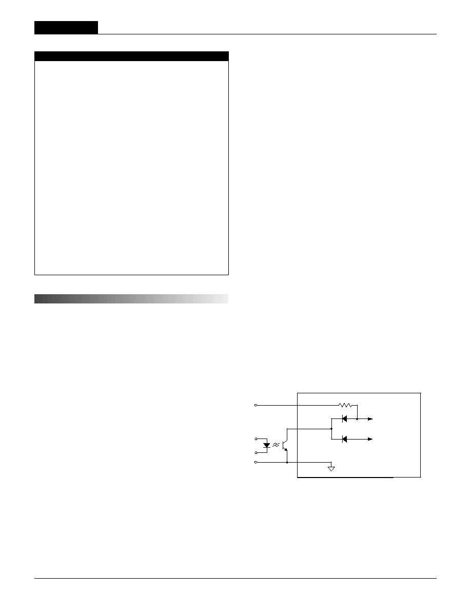
Figure 2. Driving the Positive Polarity On/Off Control Pin
4
UWR Models
2 6 - 4 0 W , S I N G L E O U T P U T D C / D C C O N V E R T E R S
Dynamic control of the remote on/off function is best accomplished with
a mechanical relay or an open-collector/open-drain drive circuit (optically
isolated if appropriate). The drive circuit should be able to sink appropriate
current (see Performance Specs) when activated and withstand appropriate
voltage when deactivated.
Applying an external voltage to pin 4 when no input power is applied to the
converter can cause permanent damage to the converter.
Sync Function (Optional)
Contact DATEL for further information.
Start-Up Time
The V
IN
to V
OUT
start-up time is the interval of time where the input voltage
crosses the turn-on threshold point, and the fully loaded output voltage enters
and remains within its specifi ed accuracy band. Actual measured times will
vary with input source impedance, external input/output capacitance, and
load. The UWR 26-40 Watt implements a soft start circuit that limits the duty
cycle of the PWM controller at power up, thereby limiting the Input Inrush
current.
The On/Off Control to V
OUT
start-up time assumes the converter has its
nominal input voltage applied but is turned off via the On/Off Control
pin. The specifi cation defi nes the interval between the time at which
the converter is turned on and the fully loaded output voltage enters
and remains within its specifi ed accuracy band. Similar to the V
IN
to V
OUT
start-up, the On/Off Control to V
OUT
start-up time is also governed by the
internal soft start circuitry and external load capacitance.
Input Overvoltage/Undervoltage Shutdown and Start-Up Threshold
Under normal start-up conditions, devices will not begin to regulate until
the ramping-up input voltage exceeds the Start-Up Threshold Voltage (35V
for "D48" models). Once operating, devices will not turn off until the input
voltage drops below the Undervoltage Shutdown limit (34V for "D48" models).
Subsequent re-start will not occur until the input is brought back up to the
Start-Up Threshold. This built in hysteresis prevents any unstable on/off
situations from occurring at a single input voltage.
Input voltages exceeding the input overvoltage shutdown specifi cation listed
in the Performance/Functional Specifi cations will cause the device to shut-
down. A built-in hysteresis of 0.6 to 1.6 Volts for all models will not allow the
converter to restart until the input voltage is suffi ciently reduced.
Current Limiting
When output power increases above the rated output current, (see Current
Limit in Performance/Functional Specifi cations) the DC/DC converter will go
into a current limiting mode. In this condition the output voltage will decrease
proportionately with increases in output current, thereby maintaining a
somewhat constant power dissipation. This is commonly referred to as
power limiting. Current limit inception is defi ned as the point where the full-
power output voltage falls below the specifi ed tolerance. See Performance/
Functional Specifi cations. If the load current being drawn from the converter
is signifi cant enough, the unit will go into a short circuit condition. See "Short
Circuit Condition."
Short Circuit Condition
When a converter is in current limit mode the output voltages will drop as
the output current demand increases. If the output voltage drops too low, the
magnetically coupled voltage used to develop primary side voltages will also
drop, thereby shutting down the PWM controller.
Following a time-out period the PWM will restart causing the output voltages
to begin ramping to their appropriate values. If the short-circuit condition
persists, another shutdown cycle will be initiated. This on/off cycling is
referred to as "hiccup" mode. The hiccup cycling reduces the average output
current, thereby preventing internal temperatures from rising to excessive
levels. The UWR 26-40 Watt A-Series is capable of enduring an indefi nite
short circuit output condition.
Thermal Shutdown
These A-Series converters are equipped with Thermal Shutdown Circuitry.
If environmental conditions cause the internal temperature of the DC/DC
converter to rise above the designed operating temperature, a precision
temperature sensor will power down the unit. When the internal temperature
decreases below the threshold of the temperature sensor the unit will self
start. See Performance/Functional Specifi cations.
Output Overvoltage Protection
The output voltage is monitored for an overvoltage condition via magnetic
coupling to the primary side. If the output voltage rises to a fault condition,
which could be damaging to the load circuitry (see Performance Specifi ca-
tions), the sensing circuitry will power down the PWM controller causing the
output voltage to decrease. Following a time-out period the PWM will restart,
causing the output voltage to ramp to its appropriate value. If the fault
condition persists, and the output voltages again climb to excessive levels,
the overvoltage circuitry will initiate another shutdown cycle. This on/off
cycling is referred to as "hiccup" mode.
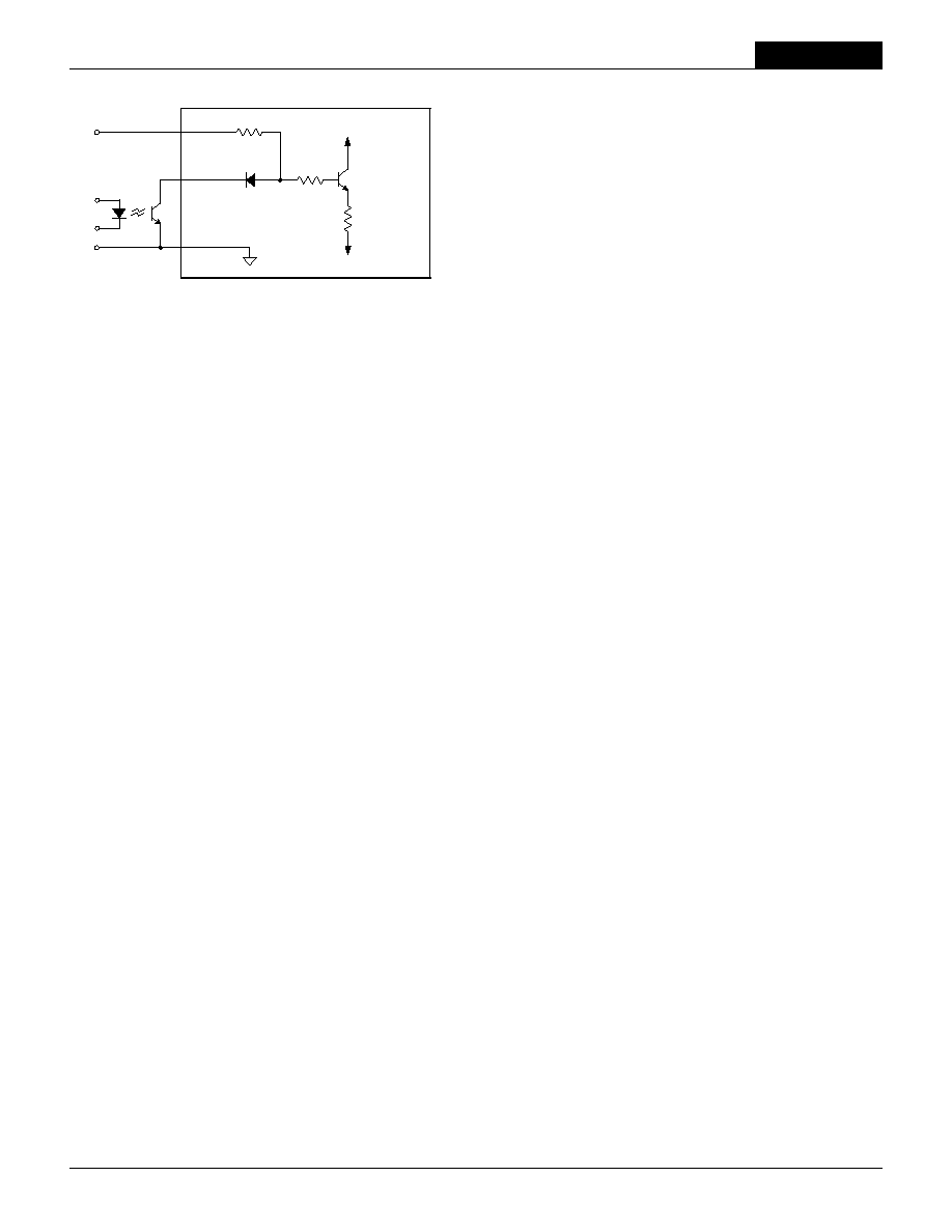
4
2
1
+INPUT
≠INPUT
ON/OFF
CONTROL
Figure 3. Driving the Negative Polarity On/Off Control Pin
5