Single Output
A-Series, UWR Models
High-Reliability, 2" x 2"
14-20 Watt, DC/DC Converters
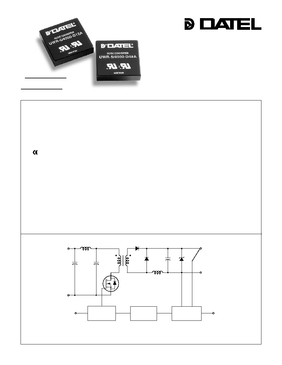
Figure 1. Simplifi ed Schematic
DATEL's new A-Series switching DC/DC converters are designed to meet
the demanding long-term-reliability and low-cost requirements of modern telecom,
datacom, computer/networking and industrial-electronics applications. These highly-
effi cient, rugged devices combine straightforward circuit topologies, new components,
proven SMT-on-pcb construction methods, and highly repeatable automatic-assembly
techniques. The fl exibility of the designs and their assembly methods readily permit
minor modifi cations to optimize performance for specifi c applications.
The single-output, 14-20 Watt Models of the A-Series deliver both high power
densities and impressive MTBF's. Their superior durability is substantiated by a
rigorous in-house qualifi cation program including HALT (Highly Accelerated Life Test-
ing), which is designed to detect any potential electrical, mechanical, or process
weaknesses.
Packaged in standard, 2" x 2" x 0.45", shielded metal cases with non-conductive
coatings, these fully isolated (1500Vdc minimum) DC/DC's offer excellent line/load
regulation, full I/O protection, thermal shutdown, and industry-standard pinouts.
Output voltages include 3.3, 5, 5.2, 12 or 15 Volts. Input voltage ranges are
DATEL's traditional ultra-wide 9-36V and 18-75V, as well as 4.7-7.5V. Each device
provides remote on/off control and V
OUT
trim capability. All A-Series UWR models are
fully EMI characterized and UL1950, CSA 950 and IEC 950 safety approved.
A-Series DC/DC's are extremely reliable, easy-to-use, cost-effective power con-
verters. Use them to improve the reliability of existing equipment or to develop
new systems that exceed design objectives.
COMMON
+V
OUT
+V
(1)
(2)
(4)
(6)
(7)
(8)
IN
≠V
IN
ON/OFF
CONTROL
+V
OUT
TRIM
REFERENCE &
ERROR AMP
OPTO
ISOLATION
PWM
CONTROLLER
DATEL, Inc., Mansfi eld, MA 02048 (USA) ∑ Tel: (508)339-3000, (800)233-2765 Fax: (508)339-6356 ∑ Email: sales@datel.com ∑ Internet: www.datel.com
Features
∑ Low cost! Highly reliable!
∑ Proven SMT-on-pcb construction
∑ Qual tested; HALT tested; EMC tested
∑ Designed to meet UL/ EN60950,
BASIC insulation (D48A models)
∑ mark available (48V
IN
models)
∑ Output voltages: 3.3/5/5.2/12/15 Volts
∑ Ultra-wide input voltage ranges:
4.7-7.5V, 9-36V or 18-75V
∑ Small packages, 2" x 2" x 0.45"
∑ Industry-standard pinouts
∑ Fully isolated, 1500Vdc guaranteed
∑ Guaranteed effi ciencies to 84%
∑ ≠40 to +100∞C operating temperature
∑ Modifi cations and customs for OEM's
INNOVATION and EX C ELL E N C E
Æ
Æ
A - S E R I E S
A Series
1 4 - 2 0 W , S I N G L E O U T P U T D C / D C C O N V E R T E R S
2
Notes:
For "D5A" and "D12A" models,
the case is connected to
pin 2 (≠V
IN
).
For "D48A" and "D48E" models, the case
is connected to pin 1 (+V
IN
).
Notes:
1. The UWR-3.3/4850-D48A (18-75V input, curve A) and UWR-3.3/4850-D12A (9-36V input,
curve A) will derate curve AA if used over the limited input ranges of 20-60V or 10-30V,
respectively.
2. "D48A" models (18-75V input ranges) that derate along curve B will derate along curve BB
if used over the more limited input range of 24-60V.
Wide Range Input
Output Confi guration:
U = Unipolar
Nominal Output Voltage:
3.3, 5, 12 or 15 Volts
Maximum Output Current
in mA
Input Voltage Range:
D5 = 4.7-7.5 Volts (5V nominal)
D12 = 9-36 Volts (24V nominal)
D48 = 18-75/36-72 Volts (48V nominal)
A-Series
High Reliability
5
U WR
4000 D12 A
-
/
-
BOTTOM VIEW
1.800
(45.72)
0.10
(2.54)
2.00
(50.80)
8
5
6
7
0.40
(10.16)
0.200
(5.08)
0.400
(10.16)
0.100
(2.54)
1
2
4
METAL CASE
INSULATED BASE
0.040 ±0.002 DIA.
(1.016 ±0.051)
2.00
(50.80)
0.20 MIN
(5.08)
0.45
(11.43)
1.200
(30.48)
3 EQ. SP. @
0.400 (10.16)
DIMENSIONS ARE IN INCHES (MM)
Typical at T
A
= +25∞C under nominal line voltage and full-load conditions unless otherwise noted.
Ripple/Noise (R/N) measured over a 20MHz bandwidth.
10% to 100% load.
UWR-3.3/4250-D5A 3.3 4250 50 100 ±1.0% ±1.0% 5 4.7-7.5 80/3720 76% 77% C4, P6
UWR-3.3/4850-D12A 3.3 4850 50 75 ±0.5% ±1.0% 24 9-36 35/852 77% 79% C4, P6
UWR-3.3/4850-D48A 3.3 4850 50 100 ±1.0% ±1.0% 48 18-75 15/419 79% 80% C4, P6
UWR-5/3000-D5A 5 3000 50 100 ±1.0% ±1.0% 5 4.7-7.5 80/3800 78% 79% C4, P6
UWR-5/4000-D12A 5 4000 50 100 ±0.3% ±0.5% 24 9-36 15/1020 81% 82% C4, P6
UWR-5/4000-D48A 5 4000 50 100 ±0.3% ±0.5% 48 18-75 15/496 82% 84% C4, P6
UWR-5/4000-D48E
5 4000 50 100 ±0.3% ±0.5% 48 36-72 15/484 84% 86% C4, P6
UWR-5.2/3000-D5A 5.2 3000 50 100 ±1.0% ±1.0% 5 4.7-7.5 80/3900 79% 80% C4, P6
UWR-12/1250-D5A 12 1250 75 120 ±1.0% ±1.0% 5 4.7-7.5 80/3660 80% 82% C4, P6
UWR-12/1650-D12A 12 1650 50 100 ±0.3% ±0.5% 24 9-36 15/1000 79.5% 82.5% C4, P6
UWR-12/1650-D48A 12 1650 75 100 ±0.3% ±0.5% 48 18-75 15/491 84% 85% C4, P6
UWR-15/1000-D5A 15 1000 75 150 ±1.0% ±1.0% 5 4.7-7.5 80/3660 80% 82% C4, P6
UWR-15/1300-D12A 15 1300 50 100 ±0.3% ±0.5% 24 9-36 20/967 84% 85% C4, P6
UWR-15/1300-D48A 15 1300 75 100 ±0.3% ±0.5% 48 18-75 10/484 84% 86% C4, P6
Performance Specifi cations and Ordering Guide
I
OUT
(mA)
R/N (mVp-p)
Load
V
OUT
(Volts)
Output
Package
(Case,
Pinout)
Effi ciency
Regulation (Max.)
Line
V
IN
Nom.
(Volts)
Range
(Volts)
Model
Input
I
IN
(mA)
Max.
Typ.
Typ.
Min.
Nominal line voltage, no-load/full-load conditions.
See Technical Notes for an explanation of trading off input voltage ranges for higher full-power
operating temperature.
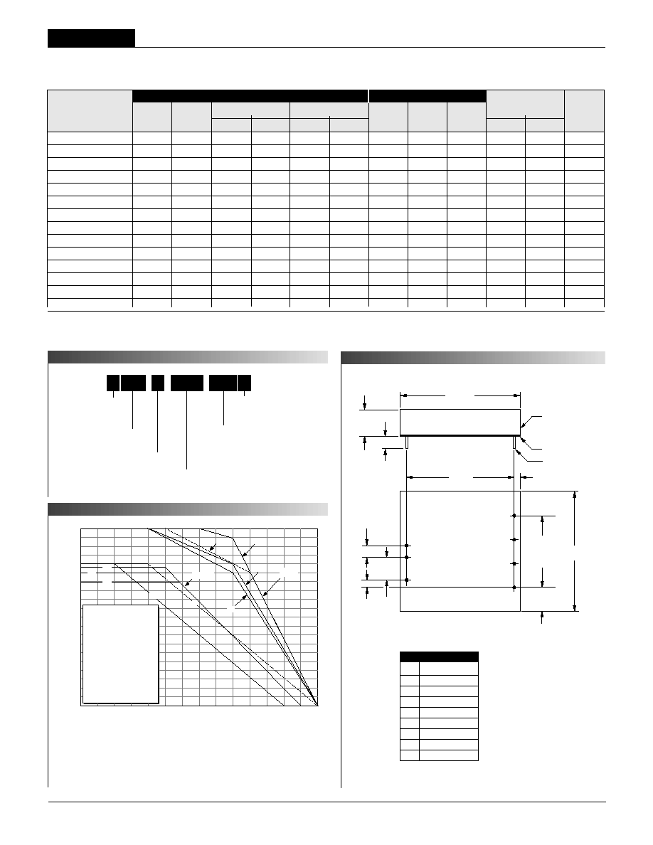
P A R T N U M B E R S T R U C T U R E
M E C H A N I C A L S P E C I F I C A T I O N S
T E M P E R A T U R E D E R A T I N G
O
u
tp
u
t
P
o
w
e
r (W
a
t
ts
)
Ambient Temperature (∞C)
20
18
16
14
12
10
8
6
4
2
0
UWR-3.3/4250-D5A F
UWR-3.3/4850-D12A A
UWR-3.3/4850-D48A A
UWR-5/3000-D5A E
UWR-5/4000-D12A C
UWR-5/4000-D48A B
UWR-5/4000-D48E G
UWR-5.2/3000-D5A D
UWR-12/1250-D5A E
UWR-12/1650-D12A C
UWR-12/1650-D48A B
UWR-15/1000-D5A E
UWR-15/1300-D12A C
UWR-15/1300-D48A B
≠40
0
40
45
50
55 60 65 70 75 80 85
90 95 100
A
AA
BB, G
C
F
E
D
D, E, F
B
BB
G
Case C4
I/O
Connections
Pin Function
P6
1 +Input
2
≠Input
3
No
Pin
4
On/Off
Control
5
No
Pin
6
+Output
7
Common
8
Trim
UWR Models
1 4 - 2 0 W , S I N G L E O U T P U T D C / D C C O N V E R T E R S
Input Voltage:
"D5A" Models 11 Volts
"D12A" Models 44 Volts
"D48A" and "D48E" Models 88 Volts
Input Reverse-Polarity Protection Current must be <10A. Brief
duration only. Fusing recommended.
Output Overvoltage Protection:
3.3V Outputs No protection
5V/5.2V Outputs 6.8 Volts, limited duration
12V Outputs 15 Volts, limited duration
15V Outputs 18 Volts, limited duration
Output Current Current limited. Max. current and
short-circuit duration are model
dependent
Storage Temperature ≠40 to +105∞C
Lead Temperature (soldering, 10 sec.) +300∞C
3
Floating Outputs
Since these are isolated DC/DC converters, their outputs are "fl oating."
Users may ground either the Common (pin 7) for normal usage or the
positive side (+Output, pin 6) to effectively reverse the output polarity.
Filtering and Noise Reduction
All A-Series UWR 14-20 Watt DC/DC Converters achieve their rated ripple
and noise specifi cations without the use of external input/output capacitors.
In critical applications, input/output noise may be further reduced by installing
electrolytic capacitors across the input terminals and/or low-ESR tantalum
or electrolytic capacitors across the output terminals. The caps should be
located as close to the power converters as possible. Typical values are
listed below. In many applications, using values greater than those listed
will yield better results.
In critical, space-sensitive applications, DATEL may be able to tailor the
internal input/output fi ltering of these units to meet your specifi c require-
ments. Contact our Applications Engineering Group for additional details.
To Reduce Input Ripple
D5A Models
47µF, 16V
D12A Models
20µF, 50V
D48A Models
20-50µF, 100V
To Reduce Output Ripple
3.3V Outputs
100µF, 6V, Low ESR
5V/5.2V Outputs
47µF, 10V, Low ESR
12/15V Outputs
22µF, 20V, Low ESR
Performance/Functional Specifi cations
Typical @ T
A
= +25∞C under nominal line voltage and full-load conditions, unless noted.
These converters require a minimum 10% loading to maintain specifi ed regulation. Operation
under no-load conditions will not damage these devices; however they may not meet all listed
specifi cations.
Application-specifi c internal input/output fi ltering can be recommended and perhaps added
internally upon request. Contact DATEL Applications Engineering for details.
Applying a voltage to the Control pin when no input power is applied to the converter
can cause permanent damage to the converter.
"D48A" models have BASIC, all other models have Functional insulation.
Devices can be screened or modifi ed for higher guaranteed isolation voltages.
Contact DATEL Applications Engineering for details.
Except for 3.3V outputs which have no protection.
Input
Input Voltage Range:
D5A Models 4.7-7.5 Volts (5V nominal)
D12A Models 9-36 Volts (24V nominal)
D48A/D48E Models 18-75/36-72 Volts (48V nominal)
Input Current See Ordering Guide
Input Filter Type
Pi (C-type for D5A models)
Overvoltage Shutdown:
D5A Models 10 Volts
D12A Models 40 Volts
D48A and /D48E Models 80 Volts
Reverse-Polarity Protection Yes (Instantaneous, 10A maximum)
On/Off (Sync.) Control (Pin 4)
TTL high = off, low (or open) = on
Output
V
OUT
Accuracy (50% load) ±1%, maximum
Temperature Coeffi cient ±0.02% per ∞C
Ripple/Noise (20MHz BW)
See Ordering Guide
Line/Load Regulation See Ordering Guide
Effi ciency See Ordering Guide
Isolation Voltage
1500Vdc guaranteed
Isolation Capacitance 550pF
Current Limiting Auto-recovery
Overvoltage Protection Zener/transorb clamp, magnetic feedback
Dynamic Characteristics
Transient Response (50% load step) 200µsec max. to ±1.5% of fi nal value
Switching Frequency 165kHz (±15kHz)
Environmental
Operating Temperature (Ambient):
Without Derating ≠40 to +40/50/55/65∞C (Model dependent)
With Derating to +100∞C (See Derating Curves)
Storage Temperature ≠40 to +105∞C
Physical
Dimensions 2" x 2" x 0.45" (51 x 51 x 11.4mm)
Shielding 5-sided
Case Connection:
D5A, D12A Models Pin 2 (≠V
IN
)
D48A, D48E Models Pin 1 (+V
IN
)
Case Material Corrosion resistant steel with
non-conductive, epoxy-based, black
enamel fi nish and plastic baseplate
Pin Material Brass, solder coated
Weight 2.7 ounces (76.5 grams)
These are stress ratings. Exposure of devices to any of these conditions may adversely
affect long-term reliability. Proper operation under conditions other than those listed in the
Performance/Functional Specifi cations Table is not implied.
Absolute Maximum Ratings
T E C H N I C A L N O T E S
A Series
1 4 - 2 0 W , S I N G L E O U T P U T D C / D C C O N V E R T E R S
4
Input Fusing
Certain applications and/or safety agencies may require the installation of
fuses at the inputs of power conversion components. For DATEL A-Series
UWR 14-20 Watt DC/DC Converters, you should use slow-blow type fuses
with values no greater than the following:
V
IN
Range Fuse Value
D5A 6A
D12A 4A
D48A/D48E 2A
On/Off Control
The On/Off Control pin (pin 4) may be used for remote on/off operation. A
TTL logic high (+2 to +5 Volts, 250µA max.) applied to pin 4 disables the
converter. A TTL logic low (0 to +0.8 Volts, 70µA max.), or no connection,
enables the converter. Control voltages should be referenced to pin 2
(≠Input). Applying a voltage to the Control pin when no input power is applied
to the converter can cause permanent damage to the converter.
Synchronization
In critical applications employing multiple switching DC/DC converters, it may
be desirable to intentionally synchronize the switching of selected converters
(so the system noise can be reduced with notch fi ltering) or to purposely
desynchronize the converters (to lessen the current-carrying requirements on
intermediate dc buses). For multiple A-Series Converters, an external clock
can be applied to pin 4 (Control) of each device. It should be a square wave
with a maximum 1µsec "high" duration and an amplitude between +2V and
+5V (see On/Off Control) referenced to pin 2 (≠Input). The frequency of the
synchronizing clock should be higher than that of any individual converter.
Therefore, it should be 185kHz ±5kHz.
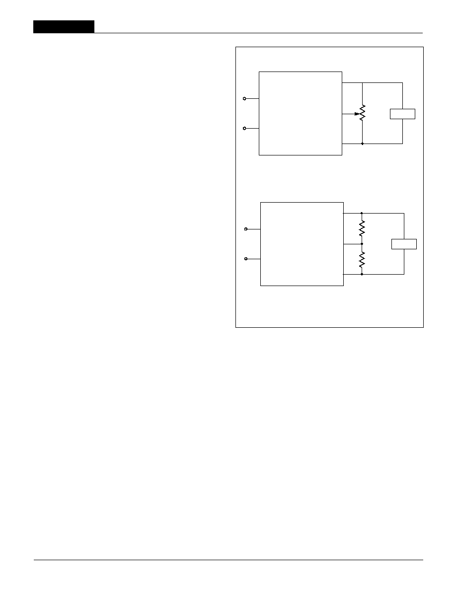
Output Trimming
V
OUT
may be trimmed ±5% via a single external trimpot or fi xed resistor. The
trimpot should be connected as shown in Figure 2a with its wiper connected
to pin 8 (Trim). A trimpot can be used to determine the value of a single
fi xed
resistor which should be connected as shown in Figure 2b. Connect the
resistor between pin 8 (Trim) and pin 6 (+Output) to trim "down" the output
voltage. Connect the resistor between pins 8 and 7 (Common) to trim "up"
the output voltage. Fixed resistors should be metal-fi lm types with absolute
TCR's less than 100ppm/∞C to ensure stability.
Figure 2a. Trim Connections Using a Trimpot
Figure 2b. Trim Connections Using Fixed Resistors
Custom Capabilities
DATEL's world-class design, development and manufacturing team stands
ready to work with you to deliver the exact power converter you need for your
demanding, large volume, OEM applications. More importantly . . . we'll do
it on time and within budget!
Our experienced applications and design staffs; quick-turn prototype capabil-
ity; highly automated, SMT assembly facilities; and in-line SPC quality-control
techniques combine to give us the unique ability to design and deliver any
quantity of power converters to the highest standards of quality and reliability.
We have compiled a large library of DC/DC designs that are currently used
in a variety of telecom, medical, computer, railway, aerospace and industrial
applications. We may already have the converter you need.
Contact us. Our goal is to provide you the highest-quality, most cost-effective
power converters available.
1
2
7
8
6
+INPUT
≠INPUT
+OUTPUT
COMMON
TRIM
LOAD
20k
5-10
TURNS
1
2
7
8
6
+INPUT
≠INPUT
+OUTPUT
COMMON
TRIM
Trim
Down
Trim Up
LOAD
UWR Models
1 4 - 2 0 W , S I N G L E O U T P U T D C / D C C O N V E R T E R S
5
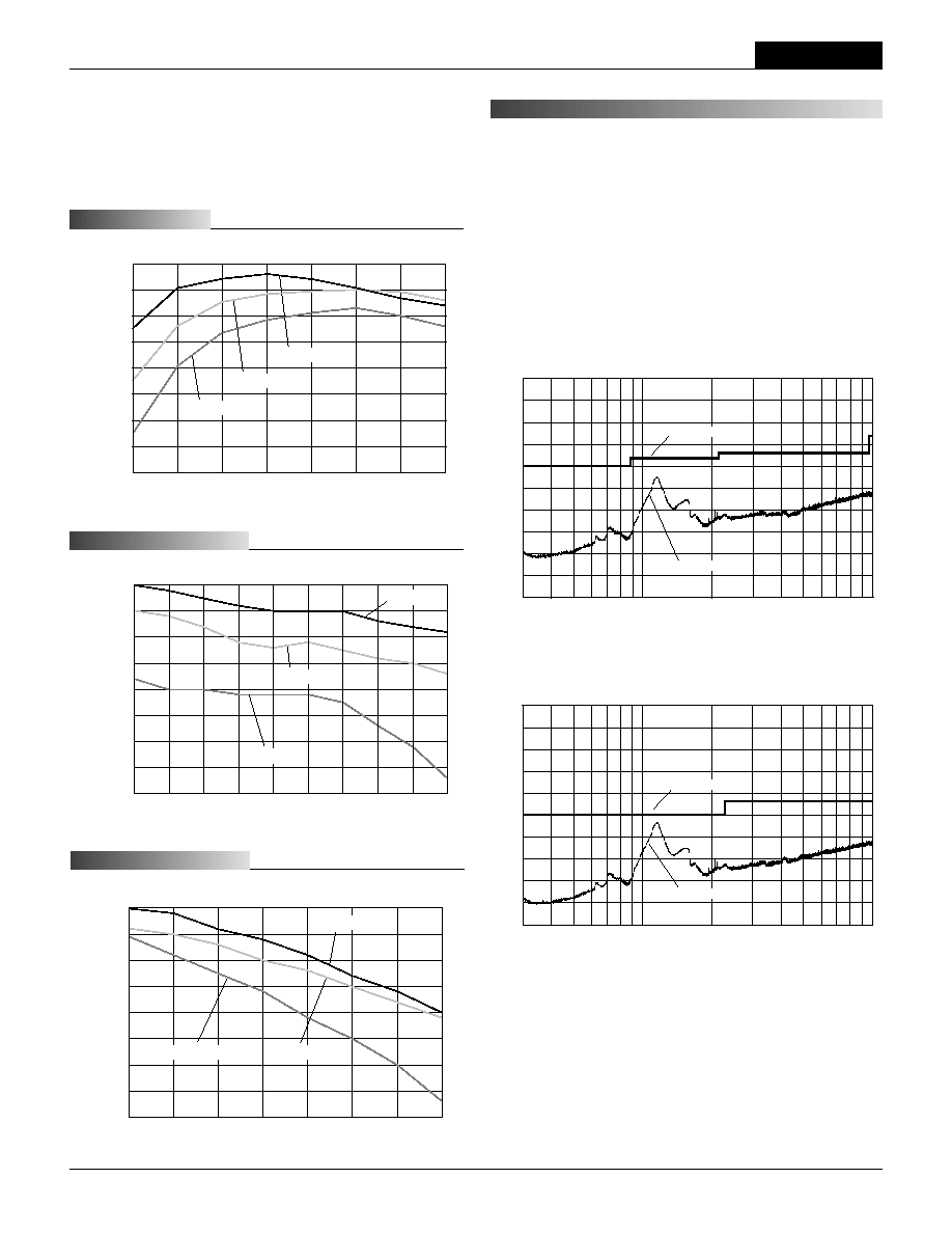
If you're designing with EMC in mind, please note that all of DATEL's UWR
14-20 Watt A-Series DC/DC Converters have been characterized for radiated
and conducted emissions in our new EMI/EMC laboratory. Testing is con-
ducted in an EMCO 5305 GTEM test cell utilizing EMCO automated EMC test
software. Radiated emissions are tested to the limits of FCC Part 15, Class
B and CISPR 22 (EN 55022), Class B. Correlation to other specifi cations can
be supplied upon request. Radiated emissions plots to FCC and CISPR 22
for model UWR-5/4000-D12A appear below. Published EMC test reports are
available for each model number. Contact DATEL's Applications Engineering
Department for more details.
Typical Performance Curves (T
A
= +25∞C)
The performance curves below were derived from actual test data for a single
model number (UWR-5/4000-D12A). Since all devices in the 14-20W UWR
A-Series have the same circuit topology, the performance curves are repre-
sentative of all devices.
Effi ciency vs. Output Current and Input Voltage
Output Voltage vs. Input Voltage and Output Current
Output Voltage vs. Output Current and Input Voltage
L I N E R E G U L A T I O N
L O A D R E G U L A T I O N
E F F I C I E N C Y
87
84
81
78
75
72
69
66
63
Ef
f
i
ci
ency (
%
)
0.5 1.0 1.5 2.0 2.5 3.0 3.5 4.0
5V Output Current (Amps)
V
IN
= 36V
V
IN
= 24V
V
IN
= 12V
5.015
5.010
5.005
5.000
4.995
4.990
4.985
4.980
4.975
V
OUT
(V
o
l
ts
)
9 12 15 18 21 24 27 30 33 36
V
IN
(Volts)
I
OUT
= 4A
I
OUT
= 2A
I
OUT
= 1A
0.5 1.0 1.5 2.0 2.5 3.0 3.5 4.0
5V Output Current (Amps)
V
IN
= 36V
V
IN
= 24V
V
IN
= 12V
5.015
5.010
5.005
5.000
4.995
4.990
4.985
4.980
4.975
V
OUT
(V
o
l
ts
)
80
70
60
50
40
30
20
10
0
≠10
≠20
Frequency (MHz)
100
1000
Radiated Emissions
FCC Class B Limit
UWR-5/4000-D12A Radiated Emissions
FCC Part 15 Class B, 3 Meters
Converter Output = 5Vdc @ 3.6A
R
a
diate
d
Em
issions
(d
Bµ
V
/
M
)
UWR-5/4000-D12A Radiated Emissions
EN 55022 Class B, 10 Meters
Converter Output = +5Vdc @ 3.6A
80
70
60
50
40
30
20
10
0
≠10
≠20
Frequency (MHz)
100
1000
Radiated Emissions
EN 55022 Class B Limit
R
a
d
i
a
t
ed
E
m
i
s
sions
(dB
µ
V
/
M
)
E M I R A D I A T E D E M I S S I O N S