
UNI-POLAR BI-POLAR
3KP5.0A
3KP5.0CA
5.0
6.40
7.00
50
9.2
326.1
5000
3KP6.0A
3KP6.0CA
6.0
6.67
7.37
50
10.3
291.3
5000
3KP6.5A
3KP6.5CA
6.5
7.22
7.98
50
11.2
267.9
2000
3KP7.0A
3KP7.0CA
7.0
7.78
8.60
50
12.0
250.0
1000
3KP7.5A
3KP7.5CA
7.5
8.33
9.21
5
12.9
232.6
250
3KP8.0A
3KP8.0CA
8.0
8.89
9.83
5
13.6
220.6
150
3KP8.5A
3KP8.5CA
8.5
9.44
10.40
5
14.4
208.3
50
3KP9.0A
3KP9.0CA
9.0
10.00
11.10
5
15.4
194.8
20
3KP10A
3KP10CA
10.0
11.10
12.30
5
17.0
176.5
15
3KP11A
3KP11CA
11.0
12.20
13.50
5
18.2
164.8
10
3KP12A
3KP12CA
12.0
13.30
14.70
5
19.9
150.8
10
3KP13A
3KP13CA
13.0
14.40
15.90
5
21.5
139.5
10
3KP14A
3KP14CA
14.0
15.60
17.20
5
23.2
129.3
10
3KP15A
3KP15CA
15.0
16.70
18.50
5
24.4
123.0
10
3KP16A
3KP16CA
16.0
17.80
19.70
5
26.0
115.4
10
3KP17A
3KP17CA
17.0
18.90
20.90
5
27.6
108.7
10
3KP18A
3KP18CA
18.0
20.00
22.10
5
29.2
102.7
10
3KP20A
3KP20CA
20.0
22.20
24.50
5
32.4
92.6
10
3KP22A
3KP22CA
22.0
24.40
26.90
5
35.5
84.5
10
3KP24A
3KP24CA
24.0
26.70
29.50
5
38.9
77.1
10
3KP26A
3KP26CA
26.0
28.90
31.90
5
42.1
71.3
10
3KP28A
3KP28CA
28.0
31.10
34.40
5
45.4
66.1
10
3KP30A
3KP30CA
30.0
33.30
36.80
5
48.4
62.0
10
3KP33A
3KP33CA
33.0
36.70
40.60
5
53.3
56.3
10
3KP36A
3KP36CA
36.0
40.00
44.20
5
58.1
51.6
10
3KP40A
3KP40CA
40.0
44.40
49.10
5
64.5
46.5
10
3KP43A
3KP43CA
43.0
47.80
52.80
5
69.4
43.2
10
3KP45A
3KP45CA
45.0
50.00
55.30
5
72.7
41.3
10
3KP48A
3KP48CA
48.0
53.30
58.90
5
77.4
38.8
10
3KP51A
3KP51CA
51.0
56.70
62.70
5
82.4
36.4
10
3KP54A
3KP54CA
54.0
60.00
66.30
5
87.1
34.4
10
3KP58A
3KP58CA
58.0
64.40
71.20
5
93.6
32.1
10
3KP60A
3KP60CA
60.0
66.70
73.70
5
96.8
31.0
10
3KP64A
3KP64CA
64.0
71.10
78.60
5
103.0
29.1
10
3KP70A
3KP70CA
70.0
77.80
86.00
5
113.0
26.5
10
3KP75A
3KP75CA
75.0
83.30
92.10
5
121.0
24.8
10
3KP78A
3KP78CA
78.0
86.70
95.80
5
126.0
23.8
10
3KP85A
3KP85CA
85.0
94.40
104.00
5
137.0
21.9
10
3KP90A
3KP90CA
90.0
100.00
111.00
5
146.0
20.5
10
3KP100A
3KP100CA
100.0
111.00
123.00
5
162.0
18.5
10
3KP110A
3KP110CA
110.0
122.00
135.00
5
177.0
16.9
10
3KP120A
3KP120CA
120.0
133.00
147.00
5
193.0
15.5
10
3KP130A
3KP130CA
130.0
144.00
159.00
5
209.0
14.4
10
3KP150A
3KP150CA
150.0
167.00
185.00
5
243.0
12.3
10
3KP160A
3KP160CA
160.0
178.00
197.00
5
259.0
11.6
10
3KP170A
3KP170CA
170.0
189.00
209.00
5
275.0
10.9
10
3KP180A
3KP180CA
180.0
200.00
233.00
5
289.0
10.4
10
For bidirectional type having Vrwm of 10 volts and less, the IR limit is double.
For parts without A , the V
BR
is + 10%
3KP SERIES
GLASS PASSIVATED JUNCTION TRANSIENT VOLTAGE SUPPRESSOR
VOLTAGE - 5.0 TO 180 Volts
REVERSE
STAND-
OFF
VOLTAGE
V
RWM
(V)
BREAKDOWN
VOLTAGE
V
BR
(V)
MIN.@I
T
REVERSE
LEAKAGE
@ V
RWM
I
R
(µA)
3000Watts Peak Pulse Power
BREAKDOWN
VOLTAGE
V
BR
(V)
MAX.@I
T
TEST
CURRENT
I
T
(mA)
MAXIMUM
CLAMPING
VOLTAGE
@Ipp Vc(V)
PEAK
PULSE
CURRENT
Ipp (A)
3KP
PART NUMBER
DB LECTRO Inc.
DB LECTRO Inc. 3600 boul. Matte suite i Brossard Qc J4Y-2Z2 tel:(450)-444-1424 fax:(450)-444-4714
FEATURES
Plastic package has Underwriters Laboratory
Flammability Classification 94V-O
Glass passivated junction
3000W Peak Pulse Power capability on 10/1000µs waveform
Excellent clamping capability
Repetition rate (duty cycle):0.05%
Low incremental surge resistance
Fast response time: typically less than 1.0ps from 0 Volts to V(BR)
Typical IR less than 1mA above 10V
High temperature soldering guaranteed: 265∞C/10 seconds/.375"
,(9.5mm) lead length, 5lbs., (2.3kg) tension
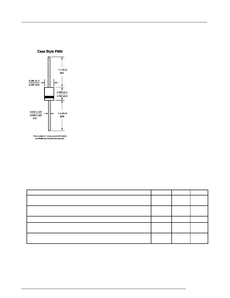
MECHANICAL DATA
Case: Molded plastic over glass passivated junction
Terminal: Plated Axial leads, solderable per MIL-STD-750, Method 2026
Polarity: Color band denotes positive end (cathode) except Bipolar
Mounting Position : Any
Weight: 0.07ounce, 2.1gram
SYMBOL VALUE
UNITS
P
PPM
Minimum
3000
Watts
I
PPM
SEE
TABLE 1
Amps
P
M(AV)
8
Watts
T
J
, T
STG
-55 to +
175
Notes :
1.Non-repetitive current pulse , per Fig. 3 and derated above T
A
= 25
per Fig. 2 .
2.Mounted on Copper Pad area of 1.6◊1.6" (40◊40mm) per Fig. 5.
3.8.3ms single half sine-wave , or equivalent square wave, Duty cycle = 4 pulses per minutes maximum.
RATING
Peak Pulse Power Dissipation on 10/1000
s waveform (Note 1,FIG.1)
Peak Pulse Current of on 10/1000
s waveform (Note 1,FIG.3)
DEVICES FOR BIPOLAR APPLICATION
MAXIMUM RATINGS AND CHARACTERISTICS
Ratings at 25
ambient temperature unless otherwise specified.
Electrical characteristics apply in both directions
For Bidirectional use C or CA Suffix for types 3KP5.0 thru types 3KP180 (e.g. 3KP5.0C , 3KP180CA)
3KP SERIES
GLASS PASSIVATED JUNCTION TRANSIENT VOLTAGE SUPPRESSOR
VOLTAGE-5.0 TO 180 Volts
3000 watt Peak Pulse Power
Amps
Steady State Power Dissipation at T
L
= 75
, Lead lengths.375",(9.5mm) (Note 2)
Superimposed on Rated Load,(JEDEC Method) (Note 3)
Operating junction and Storage Temperature Range
I
FSM
400
Peak Forward Surge Current,8.3ms Single Half Sine-Wave
DB LECTRO Inc.
DB LECTRO Inc. 3600 boul. Matte suite i Brossard Qc J4Y-2Z2 tel:(450)-444-1424 fax:(450)-444-4714

Ratings and
Characteristic Curves
(T
A
=25
unless otherwise noted)
3KP SERIES
RATINGS AND CHARACTERISTIC CURVES 3KP SERIES
10
100
1000
1
10
100
200
Number of Cycles at 60 Hz
Fig.6 - Maximum Non-Repetitive Forward
Surge Current Uni-Directional Only
8.3ms Single Half Sine-Wave
(JEDEC Method)T
J
=T
J
max.
I
FSM
-Peak Forward Surge Current (A)
P
M(AV)
,Steady State Power
Dissipation (W)
0
25
50
75
100
125
150
175
200
0
1.0
2.0
3.0
4.0
Fig. 5 - Steady State Power
Derating Curve
T
L
- Lead Temperature (∞C)
L=0.375" (9.5mm)
Lead Lengths
1.6x1.6x.040"
(40x40x1mm)
Copper Heat Sinks
5.0
6.0
7.0
8.0
60Hz
Resistive or
Inductive Load
t - Time(ms)
3.0
4.0
150
0
1.0
2.0
t
r
= 10µsec.
Peak Value
I
PPM
T
J
= 25∞C
Pulse Width(td)is defined
as the point where the
peak current decays to
50% of I
PPM
10/1000µsec.Waveform
as defined by R.E.A.
td
Fig.3 - Pulse Waveform
4.0
50
Half Value- I
PPM
2
100
I
PPM
- Peak Pulse Current,% I
RSM
3.0
0
10
100
1000
10000
1
10
100
1000
5
10
100
1000
10000
C
J
- Capacitance (pF)
Fig. 4 - Typical Junction Capacitance
VWM - Reverse Stand-Off Voltage (V)
Unidirectional
Bidirectional
f = 1MHz
Vsig = 50mVp-p
T
J =
25∞C
V
R
= 0
500
V
R
= Rated
Stand-off Voltage
10
0
12.5
25
37.5
50
62.5
75
87.5
100
0
25
50
75
100
125
150
175
200
Fig.2 - Pulse Derating Curve
Peak Pulse Power (P
PP
)
or Current (I
PP
)
Derating in Percentage,%
T
A
- Ambient Temperature (∞C)
0.1
1
10
100
10ms
0.1µs
1.0µs
10µs
100µs
1.0ms
t
d
- Pulse Width (sec.)
Fig. 1 - Peak Pulse Power Rating Curve
P
PP
M
-Peak Pulse Power (kW)
Non-repetitive pulse
waveform shown in
Fig.3 T
A
= 25∞C
DB LECTRO Inc.
DB LECTRO Inc. 3600 boul. Matte suite i Brossard Qc J4Y-2Z2 tel:(450)-444-1424 fax:(450)-444-4714