1
Electrical characteristics(23
)
Resistance
Tolerance
Hold
Current
Trip
Current
Max.Time
to Trip
Maximum
Current
Rated
Voltage
Typical
Power
R
MIN
R
1
MAX
Part
Number
I
H
,
A
I
T
,
A
at 8A at 5xI
H
I
MAX
,A
V
MAX
,V
dc
Pd, W
FUSB075
0.75
1.30
0.4
--
40
16/30
0.3
0.080
0.23
FUSB090
0.90
1.80
1.2
5.9
40
16/30
0.6
0.070
0.18
FUSB110
1.10
2.20
2.3
6.6
40
16/30
0.7
0.050
0.14
FUSB120
1.20
2.00
0.5
--
40
16/30
0.6
0.040
0.14
FUSB135
1.35
2.70
4.5
7.3
40
16/30
0.8
0.040
0.12
FUSB155
1.55
2.70
0.6
--
40
16/30
0.7
0.030
0.12
FUSB160
1.60
3.20
9.0
8.0
40
16/30
0.9
0.030
0.11
FUSB185
1.85
3.70
10.0
8.7
40
16/30
1.0
0.030
0.09
FUSB250
2.50
5.00
40.0
10.3
40
16/30
1.2
0.020
0.07
I
H
=Hold current-maximum current at which the device will not trip at 23
still air.
I
T
=Trip current-minimum current at which the device will always trip at 23
still air.
V
MAX
=Maximum voltage device can withstand without damage at its rated current.
I
MAX
= Maximum fault current device can withstand without damage at rated voltage (V max).
Pd=Typical power dissipated from device when in the tripped state in 23
still air environment.
R
MIN
=Minimum device resistance at 23 .
R
1
MAX
=Maximum device resistance at 23
, 1 hour after tripping .
Physical specifications:
Lead material: Tin plated copper,24 AWG.
Soldering characteristics: Soldering ability per ANSI/J-STD 002
Solder heat withstand per IEC 68-2-20
FUSB 120 :Test Tb, method 1a, condition a; can withstand 5 second at 260
5
All others: Test Tb, method 1a, condition a; can withstand 10 second at 260
5
Insulating coating:Flame retardant epoxy polymer ,meets UL 94V-O requirement.
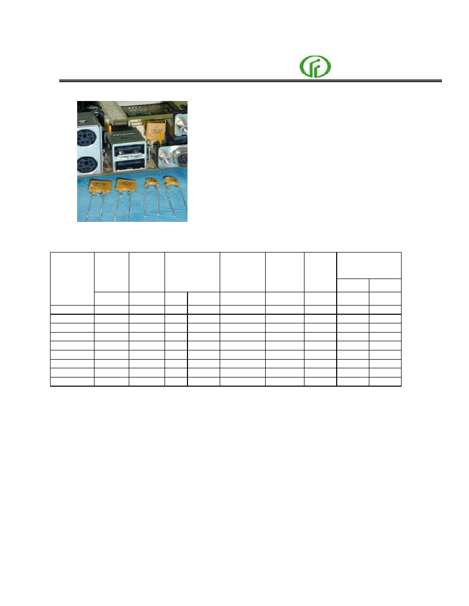
Application:
Low voltage USB equipment
Product Features:
Low resistance, Fast trip time , Lower
Trip-to-hold Ratio
Operation Current: 750mA ~2.5A
Maximum Voltage: 16V/30V
Temperature Range: -40
to 85
Agency Approvals: UL(E211981),
C-UL(E211981),
TUV (R3-50004084)
Radial Leaded PTC FUSB Series
FUZETEC
DB LECTRO Inc., 3600-I, boulevard Matte, Brossard, QC J4Y 2Z2
2
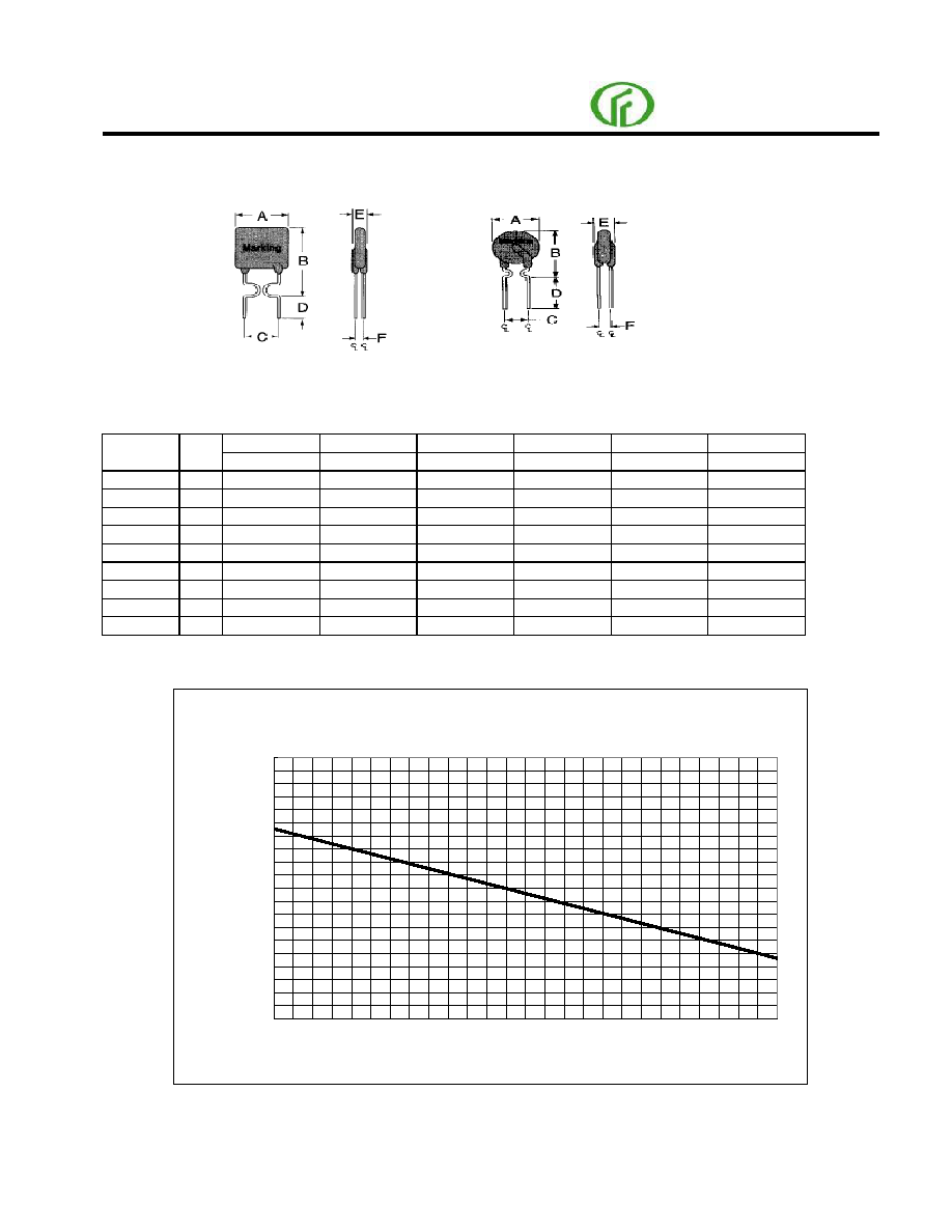
FUSB Product Dimensions (millimeters)
Lead Size :24AWG,
Lead Size : 24AWG
0.51 mm Diameter
0.51 mm Diameter
A
B
C
D
E
F
Part
Number
Fig
Maximum
Maximum
Typical
Minimum
Maximum
Typical
FUSB075
2
6.9
11.4
5.1
7.6
3.0
0.8
FUSB090
1
7.4
12.2
5.1
7.6
3.0
0.8
FUSB110
1
7.4
14.2
5.1
7.6
3.0
0.8
FUSB120
2
6.9
11.7
5.1
7.6
3.0
0.8
FUSB135
1
8.9
13.5
5.1
7.6
3.0
0.8
FUSB155
2
6.9
11.7
5.1
7.6
3.0
0.8
FUSB160
1
8.9
15.2
5.1
7.6
3.0
0.8
FUSB185
1
10.2
15.7
5.1
7.6
3.0
0.8
FUSB250
1
11.4
18.3
5.1
7.6
3.0
0.8
Thermal Derating Curve
Figure 1
Figure 2
Thermal Derating Curve - FUSB Series
0%
50%
100%
150%
200%
-40
-20
0
20
40
60
80
Ambient Temperature (C)
P
ercen
t
o
f
R
ated
Hold
an
d
T
rip
C
u
rren
t
Radial Leaded PTC FUSB Series
FUZETEC
DB LECTRO Inc., 3600-I, boulevard Matte, Brossard, QC J4Y2Z2
3
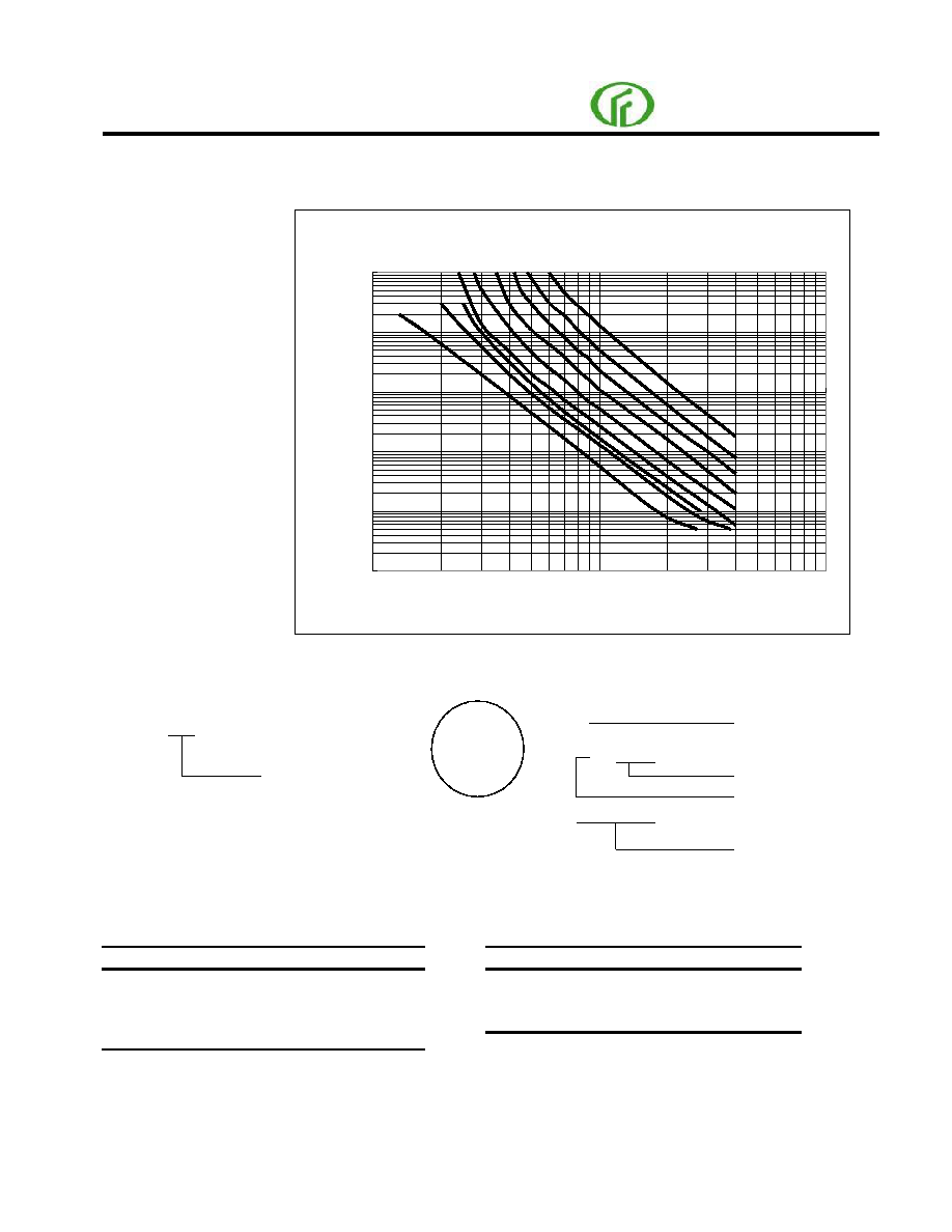
Typical Time-To-Trip at 23
A
B C D E F G H I
0.001
0.01
0.1
1
10
100
1
10
100
Fault current (A)
T
i
m
e
-to
-
tri
p
(S
)
Part numbering system
Part marking system
F U S B
Current rating
Example
Standard Package
P/N
Pcs /Bag
Reel/Tape
P/N
Pcs /Bag
Reel/Tape
FUSB075
500
3K
FUSB155
500
3K
FUSB090
500
3K
FUSB160
500
3K
FUSB110
500
3K
FUSB185
500
3K
FUSB120
500
3K
FUSB250
500
3K
FUSB135
500
3K
A =FUSB075
B = FUSB120
C = FUSB155
D = FUSB090
E = FUSB110
F = FUSB135
G = FUSB160
H = FUSB185
I = FUSB250
F
Fuzetec Logo
UB
Part Identification
Product Family
Date Code/Lot Number
F
UB110
09AB
Radial Leaded PTC F
USB Series
FUZETEC
DB LECTRO Inc., 3600-I, boulevard Matte, Brossard, QC J4Y 2Z2