
Miniature PCB / QC Power Relay
HG4138B
HG4138B
1/2
FEATURES
30A switching capacity
PCB + QC termination
Meets UL508 and UL873
spacing requirements
TYPICAL APPLICATIONS
Power supply device
Industrial control
Home appliances
Heating, refrigeration, ventilation
CONTACT RATING
UL /CSA RATING
CONTACT DATA
COIL DATA
General Purpose
Resistive
Motor
LRA/FLA
Tungsten
Ballast
Material
Service Life
Initial Contact Resistance
Form
Rated Load
Max. Switching Current
Max. Continuous Current
Max. Switching Power
Min. Load
Max. Switching Voltage
240VAC
30A
15A
20A
10A
10A
10A
20A
20A
20A
10A
2.77KVA
300W
5.54KVA
600W
15A
4.155KVA
450W
15A
10A
8.31KVA
900W
1A, 5VDC/12VAC
30A
30A
277VAC/30VDC
30A
1 Form A (1H)
1 Form B (1D)
NO
NC
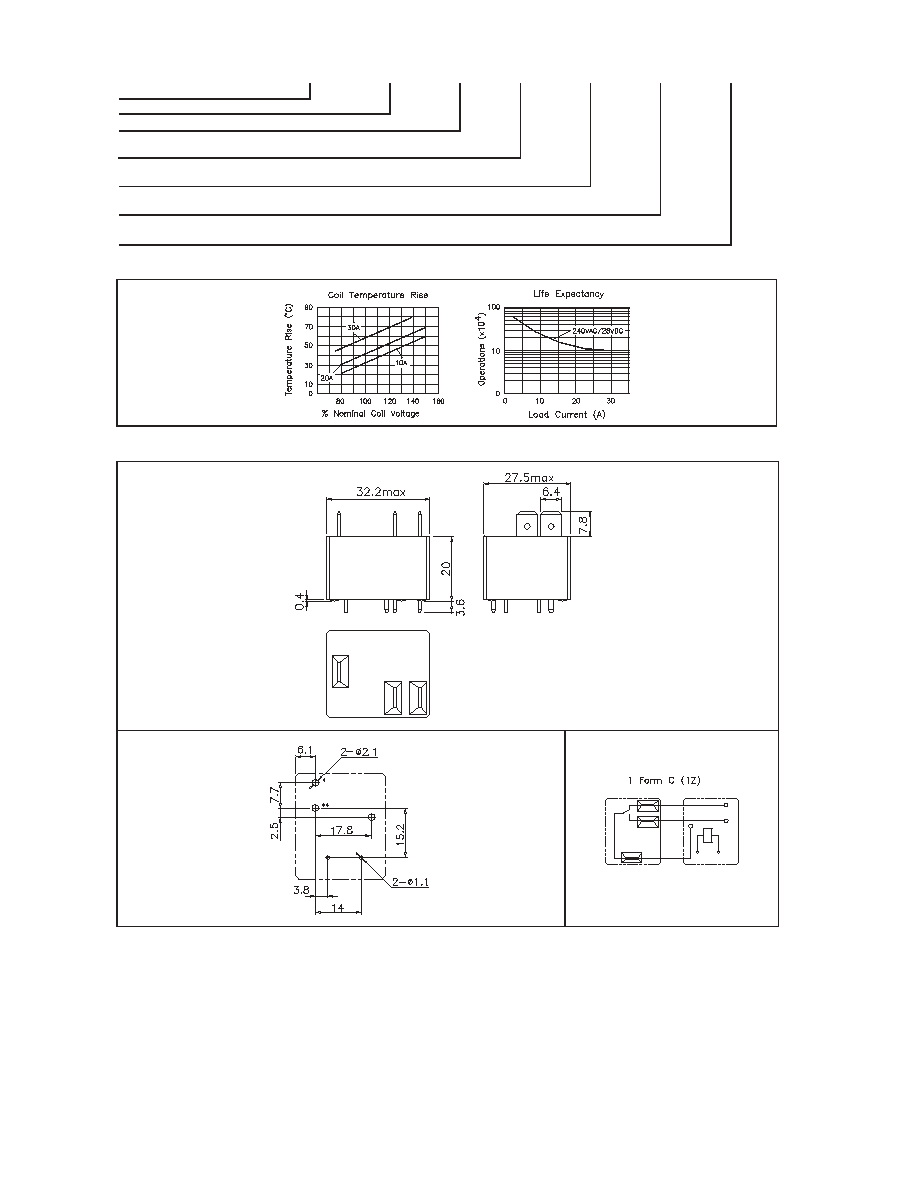
1 Form C (1Z)
28VDC
Load Type
Voltage
1 Form A (1H)
1 Form B (1D)
1 Form C (1Z)
240VAC
30A
15A
20A
10A
10A
10A
20A
20A
NO
NC
15A
10A
30A
20A
2HP
0.5HP
30A /10A
50A /20A
20A /7A
0.25HP
0.5HP
0.25HP
TV5
TV5
TV3
TV3
10A
10A
3A
3A
1HP
2HP
1HP
80A /30A
98A /22A
240VAC
240VAC
120VAC
240VAC
277VAC
AgCdO, AgSnOInO
50 m
, max. at 0.1A, 6VDC
10
7
ops.
10
5
ops.
Mechanical
Electrical
120VAC
120VAC
28VDC
Coil Voltage
Code
Nominal Voltage
(VDC)
Resistance
(
) ±10%
Must Operate
(VDC)
Voltage max.
Must Release
(VDC)
Voltage min.
005
006
009
012
024
048
110
5
6
9
12
24
48
110
27
40
97
155
660
2560
10330
3.75
4.50
6.75
9.00
18.00
36.00
82.50
0.5
0.6
0.9
1.2
2.4
4.8
11.0
CHARACTERISTICS
Operate Time
Release Time
Insulation Resistance
Dielectric Strength
Shock Resistance
Vibration Resistance
Power Consumption
Ambient Temperature
Weight
15 ms. typical
10 ms. typical
1000 M
, at 500VDC, 50%RH
1500 Vrms, 1 min. between open contacts
2500 Vrms, 1 min. between coil and contacts
10 g, 11ms, functional; 100 g, destructive
DA 1.5mm. 10 - 55 Hz
0.9W, approx.
30 g, approx.
-55 to 85∫C operating, -40 to 130∫C storage
HG4138B
HG4138B
2/2
REFERENCE CURVES
OVERALL DIMENSIONS, MOUNTING HOLES AND WIRING DIAGRAM (mm)
Overall Dimensions
Mounting Holes (Bottom View)
Wiring Diagram (Top View)
NOTES
1.
All parameters, unless otherwise specified, are measured at ambient temperature 23∫C.
2.
In mounting holes drawing, the * holes is not needed for 1 Form A, the ** hole is not needed for 1 Form B.
3.
To exert optimum electrical life, please remove the tape of sealed version after cleaning process.
4.
Custom-made services available with operational quantity. Please let us know your special requirements.
5.
Specifications subject to change without prior notice.
COM
NO
NC
ORDERING DESIGNATION
Example:
HG4138B /
012 -
1Z
0
1
F
Model
Coil Voltage Code
Contact Form
Mounting Version
Version
Thermal Class
1H: 1 Form A; 1D: 1 Form B; 1Z: 1 Form C
0: PCB Mount
1: Sealed; 2: Dust Cover
Nil: UL Class B; F: UL Class F
DB LECTRO INC. 3600 boul. Matte suite I Brossard Qc J4Y-2Z2
TEL:(450)-444-1424 FAX: (450)-444-4714