Subminiature PCB Telecom Relay
HG4516
HG4516
1/2
FEATURES
CONTACT RATING
COIL DATA
SINGLE COIL LATCHING
DUAL COIL LATCHING
SINGLE SIDE STABLE
CONTACT DATA
Form
Nominal
Resistance (
) ±10%
Power Consumption
Must Operate
Voltage max.
Voltage
(VDC)
Designation
(VDC)
Allowable Operate
Voltage Range.
(VDC)
Must Release
Voltage min.
(VDC)
Material
Mechanical
Electrical
Service Life
Initial Contact Resistance
Rated Load
Max. Switching Current
Max. Switching Voltage
Max. Switching Power
005-AL
5
167
0.15W
4.0
11.5
13.8
20.8
27.7
34.6
55.4
10.0
12.0
18.0
24.0
30.0
48.0
96.0
0.5
0.6
0.9
1.2
1.5
2.4
0.5
0.6
0.9
1.2
1.5
2.4
4.8
3.5
4.2
6.3
8.4
4.8
7.2
9.6
12.0
19.2
10.5
16.8
36.0
0.2W
240
540
960
1500
3840
125
405
720
1125
2880
11520
180
6
9
12
15
24
5
6
9
12
15
24
5
6
9
12
15
24
5
6
9
12
15
24
5
6
9
12
15
24
167
240
540
960
1500
3840
125
180
405
720
1125
2040
4.00
4.80
7.20
9.60
12.00
19.20
3.75
4.50
6.75
9.00
11.25
18.00
11.5
13.8
20.8
27.7
34.6
55.4
10.0
12.0
18.0
24.0
30.0
48.0
330
0.075W
0.2W
0.1W
0.15W
480
1080
1920
3000
7680
250
360
810
1440
2220
4000
4.00
4.80
7.20
9.60
12.00
19.00
3.75
4.50
6.75
9.00
11.25
18.00
16
19
29
39
43
78
14
17
25
34
42
56
5
6
9
12
15
24
48
006-AL
009-AL
012-AL
015-AL
024-AL
005-AH
006-AH
009-AH
012-AH
015-AH
024-AH
048-AH
005-BJ
006-BJ
009-BJ
005-BM
006-BM
009-BM
012-BJ
015-BJ
024-BJ
012-BM
015-BM
024-BM
005-CL
006-CL
009-CL
005-CH
006-CH
009-CH
012-CL
015-CL
024-CL
012-CH
015-CH
024-CH
Designation
Designation
Nominal Voltage
Resistance (
) ±10%
Set and Reset
Voltage max.
(VDC)
Set and Reset
Voltage max.
(VDC)
Allowable
Voltage
(VDC)
Allowable
Voltage
(VDC)
Power Consumption
Resistance (
) ±10%
Power Consumption
(VDC)
Nominal Voltage
(VDC)
TYPICAL APPLICATIONS
Low profile and light weight
Telecommunications
available
2 Form C (2Z)
5A
2A, 30VDC; 1A, 125VAC
220VDC/250VAC
60W/125VA
Industrial process control
Remote control
Ag alloy + Au clad
50 m
max. at 0.01A, 6VDC
5 x 10
5
ops at 1A, 30VDC
10
8
ops.
10
5
ops at 2A, 30VDC;
Single side stable and magnetic latching version
Computer
Highly reliable performance
Office machine
DIL configuration as IC and for use with DIP socket
Instruments
HG4516
HG4516
2/2
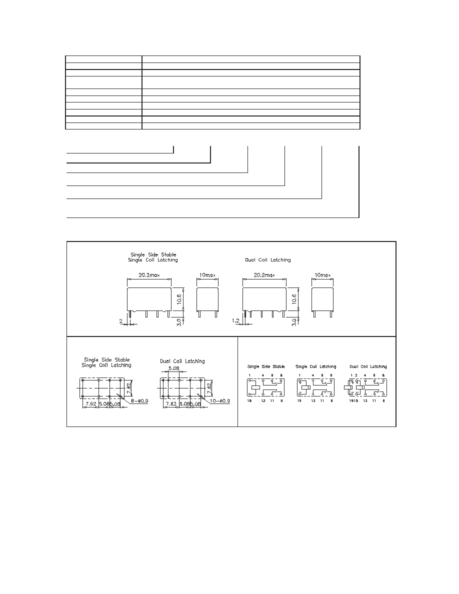
OVERALL DIMENSIONS, MOUNTING HOLES AND WIRING DIAGRAMS (mm)
Overall Dimensions
Mounting Holes (Bottom View)
Wiring Diagrams (Bottom View)
ORDERING DESIGNATION
Model
Version
Coil Sensitivity
1: Sealed
L: 0.15W; H: 0.2W
J: Sensitive 0.075W; M: Sensitive 0.1W*
A: Single Side Stable
* Sensitive versions J and M are for single coil latching version only
B: Single Coil Latching; C: Dual Coil Latching
Coil Voltage Code
Example:
HG4516 /
012 -
1
A
H
CHARACTERISTICS
Operate Time
Release Time
Insulation Resistance
Dielectric Strength
Surge Strength
Shock Resistance
Vibration Resistance
Power Consumption
Ambient Temperature
Weight
4 ms.
Standard 0.15 - 0.2W, Sensitive 0.075 - 0.1W
1500 V
2 g
-40 - 85 C operating
8 g, approx.
5 g, 11ms. functional; 10 g, 11ms. destructive
1000 M
at 500VDC
1500 Vrms, 1 min. between coil and contacts
1000 Vrms, 1 min. between open contacts
3 ms.
NOTES
1.
All parameters, unless otherwise specified, are measured at ambient temperature 20∫C.
2.
For single coil latching version the wiring diagram show reset position. Energize terminal 1 and 16 to set and reverse energize the
terminal 1 and 16 to reset.
3.
For dual coil latching version the wiring diagram show reset position. Energize terminal 1 and 16 to set and energize the terminal
2 and 15 to reset.
4.
Custom-made services available with operational quantity. Please let us know your special requirements.
5.
Specifications subject to change without prior notice.
DB LECTRO INC. 3600 boul. Matte suite I Brossard Qc J4Y-2Z2
TEL: (450)-444-1424 FAX: (450)-444-4714