Features
Magnet latching relay.
High sensitivity & reliability.
Well anti-shock and anti-vibration.
Heavy contact load.
Ordering Information
NE720 A Z DC12V
1 2 3 4
1 Part number
NE720
2 Contact arrangement
A:1A
B:1B
3 Enclosure
Z: Dust cover
4 Coil rated Voltage(V)
DC:6,12, 24
Contact Data
Contact Arrangement
1A SPSTNO
1B SPSTNC
Contact Material
Ag SnO
2
Contact Rating(resistive)
100A
m
ax/240VAC
Max. Switching Power
23000VA(COS =1) 2300VA(COS =0.4)
Max. Switching Voltage
400VAC Max. Switching Current:100A
Contact Resistance or Voltage drop
1m Item 3.12 of IEC255-7
Electrical
(Rated load)
10
4
Item 3.30 of IEC255-7
Operation life
Mechanical
(No load)
10
6
Item 3.31 of IEC255-7
Coil Parameter
DASH
NUMBERS
COIL
RATED
VOLTAGE
VDC
COIL
RESISTANCE
±
10%
SWITCHING
VOLTAGE
VDC
(<80% of
rated
voltage)
OPERATING
VOLTAGE
RANGE
VDC
PULSE
MAGNITUDE
ms
COIL
POWER
CONSUMPTION
W
Operate
Time
ms
Reset
Time
ms
2 COIL
006-4500
6
2
y
8
<4.8
4.9~10
012-4500
12
2
y
32
<9.6
9.8~20
024-4500
24
2
y
130
<19.2
19.7~40
36
4.5
12
6
1 COIL
006-2250
6
16
<4.8
4.9~10
012-2250
12
64
<9.6
9.8~20
024-2250
24
260
<19.2
19.7~40
36
2.25
12
6
CAUTION
:
1.When latching relays are installed in equipment, the latch and reset coil should not be pulsed simultaneously.
coil should not be pulsed with less than the nominal coil voltage and pulse width should be a minimum of three
times the specified operate time of the relay. If these conditions are not followed, it is possible for the relay to in
be the magnetically neutral position .
2.Switching voltage is for test purpose only and are no to be used as design criteria.
153
N E 7 2 0
60
×
40
×
22
CH0054066--2000
www.dblectro.com
Operation condition
Insulation Resistance
1000M min (at 500VDC)
Item 7 of IEC255-5
Dielectric Strength
Between contacts
Between contact and coil
50Hz 2000V surge Voltage 2kV
50Hz 4000V surge Voltage 12kV
Item 6 and 8 of IEC255-5
Item 6 and 8 of IEC255-5
Creepage distance
8.4mm
Addenda B of IEC255-5
Shock resistance
Functional 100m/s
2
;Survival:1000 m/s
2
11ms
IEC68-2-27 Test Ea
Vibration resistance
10~55Hz Double amplitude 1.5mm
IEC68-2-6 Test Fc
Terminals strength
5N; 2.5N
h
m
IEC68-2-21 Test Ua1and Ud
Solderability
235
x
2
3
x
0.5s
IEC68-2-20 Test Ta method 1
Ambient Temperature
-25~70
Relative Humidity
85% (at 40
)
IEC68-2-3Test Ca
Mass
82g
Qualification inspection:
Perform the qualification test as specified in the table
of IEC255-19-1 and minimum sample size 24.
Safety approvals
Safety approval
CCEE
Load
100A/250VAC
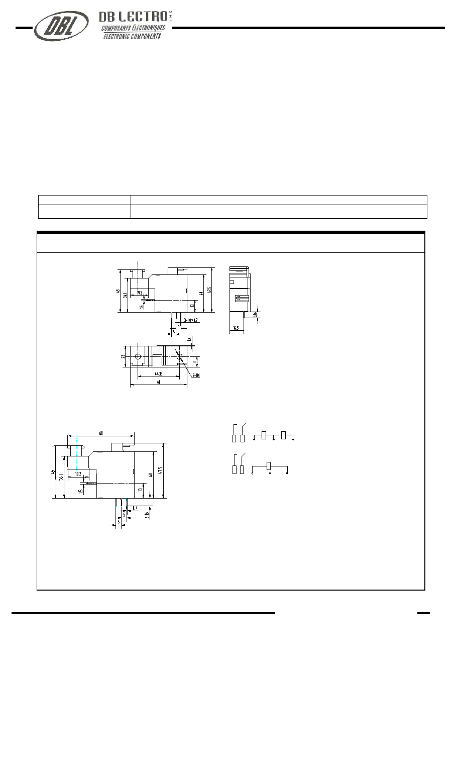
Dimensions
(Unit: mm)
3(-)
4(+)
2(-)
NE720
Dimensions
Mounting (Bottom views)
Wiring diagram
4
2(+)
3
mm inch
0.4
0.016
0.6
0.024
0.7
0.027
5.0
0.197
6.0
0.236
6.16
0.243
11.0
0.433
12.0
0.472
13.0
0.512
14.5 0.571
15.0
0.597
19.2
0.756
22.0
0.866
36.1
1.441
40.0
1.575
44.35
1.746
45.0
1.772
47.5 1.870
60.0 2.362
NOTES 1
).Dimensions are in millimeter.
2).Inch equivalents are given for general information only.
3).Relays shall have plus(+) or plus(+) and minus(-) signs placed on
the circuit diagram as shown.
www.dblectro.com