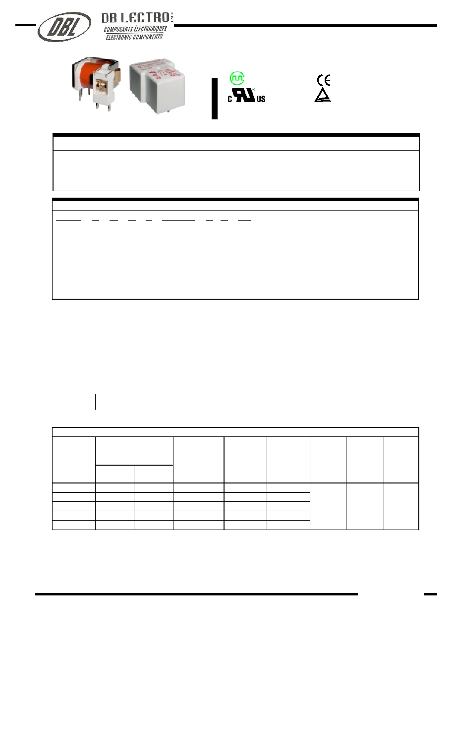
NT90 (T90)
Features
Small size, light weight. Low coil power consumption, heavy contact load. Strong anti-shock and anti-vibration, high
reliability, long life.
Suitable for automobile, machine, electronic equipment, air conditioner and household appliance applications.
PC board mounting.
Ordering Information
NT90 R H A S DC12V C
B 0.9
1 2 3 4 5 6 7 8 9
1 Part number
NT90T
NT90T
2
2 Terminal
R: without Pin 6
NIL: With Pin 6
3 Load
H:30A
N:40A
4 Contact arrangement
1A:1A
1B:1B
1C:1C
5 Enclosure
S: Sealed type
D: Dust cover
E: Covered
O: Open type
6 Coil rated Voltage(V)
AC:12,24,110,120,220
DC:3,5,6,9,12,15,18,24,48,110
7 Contact material
C: Ag CdO
S: Ag SnO
2
8 Resist heat class
B:130
F:155
9 Coil power consumption
0.6:0.6W
0.9:0.9W
NIL:2VA
Contact Data
Contact Arrangement
1A SPSTNO
f
1B(SPSTNC)
f
1C(SPDT(B-M))
Contact Material
Ag CdO Ag SnO
2
Ag SnO
2
In
2
O
3
Contact Rating (resistive)
NO : 30A/240VAC,14VDC; NC:20A/240VAC ;30A/14VDC
NO
40A/250VAC,30VDC; NC:30A/250VAC,30VDC (0.9W)
Motor load
2HP 250VAC
1.5HP 250V
Lamp load
TV-5
Max. Switching Power
1100W 7200VA
Max. Switching Voltage
110VDC 250VAC Max. Switching Current:40A
Contact Resistance or Voltage drop
30m Item 3.12 of IEC255-7
Electrical
10
5
Item 3.30 of IEC255-7
Operation
life
Mechanical
10
7
Item 3.31 of IEC255-7
Coil Parameter
AC Coil Parameter
RATED VOLTAGE
VAC
DASH
NUMBERS
RATED
Max
COIL
RESISTANCE
±
10%
PICK UP
VOLTAGE
VAC(max)
(75%of
rated
voltage)
RELEASE
VOLTAGE
VAC(min)
(30%of
rated
voltage)
COIL
POWER
Operate
Time
ms
Release
Time
ms
012AC
12
15.6
27
9.0
3.6
024AC
24
31.2
120
18.0
7.2
110AC
110
143
2360
82.5
33.0
120AC
120
156
3040
90.0
36.0
220AC
220
286
13490
165.0
66.0
2VA
_
_
CAUTION
: 1.The use of any coil voltage less than the rated coil voltage will compromise the operation of the relay.
2.Pickup and release voltage are for test purposes only and are not to be used as design criteria.
103
30.5
×
24.2
×
17 32.5
×
27.6
×
20.5
E160644
R2033977.05
Patent No. 95213824.7 99218304.9
99312549.2 01311661.4
CH0050401--2000
E9930952E01
www.dblectro.com

Coil Parameter
DC Coil Parameter
RATED VOLTAGE
VDC
DASH
NUMBERS
RATED
Max
COIL
RESISTANCE
±
10%
PICK UP
VOLTAGE
VDC(max)
(75%of
rated
voltage)
RELEASE
VOLTAGE
VDC(min)
(10%of
rated
voltage)
COIL
POWER
W
Operate
Time
ms
Release
Time
ms
003-900
3
3.9
10
2.25
0.3
005-900
5
6.5
28
3.75
0.5
006-900
6
7.8
40
4.50
0.6
009-900
9
11.7
90
6.75
0.9
012-900
12
15.6
160
9.00
1.2
015-900
15
19.5
250
10.25
1.5
018-900
18
23.4
360
13.50
1.8
024-900
24
31.2
640
18.00
2.4
048-900
48
62.4
2560
36.00
4.8
110-900
110
143
13445
82.50
11.0
0.9
15
10
003-600
3
3.9
15
2.25
0.3
005-600
5
6.5
42
3.75
0.5
006-600
6
7.8
60
4.50
0.6
009-600
9
11.7
135
6.75
0.9
012-600
12
15.6
240
9.00
1.2
015-600
15
19.5
375
10.25
1.5
018-600
18
23.4
540
13.50
1.8
024-600
24
31.2
960
18.00
2.4
048-600
48
62.4
3840
36.00
4.8
110-600
110
143
20167
82.50
11.0
0.6
15
10
CAUTION
: 1.The use of any coil voltage less than the rated coil voltage will compromise the operation of the relay.
2.Pickup and release voltage are for test purposes only and are not to be used as design criteria.
Qualification inspection:
Perform the qualification test as specified in the table
of IEC255-19-1 and minimum sample size 24.
Operation condition
Insulation Resistance
1000M min (at 500VDC)
Item 7 of IEC255-5
Dielectric Strength
Between contacts
Between contact and coil
50Hz 1500V
50Hz 2500V 4000V without Pin 6
Item 6 of IEC255-5
Item 6 of IEC255-5
Shock resistance
200m/s
2
11ms
IEC68-2-27 Test Ea
Vibration resistance
10~55Hz double amplitude 1.5mm
IEC68-2-6 Test Fc
Terminals strength
10N
IEC68-2-21 Test Ua1
Solderability
235
x
2
3
x
0.5s
IEC68-2-20 Test Ta method 1
Ambient Temperature
-55~100
-55~125
Relative Humidity
85% (at 40
)
IEC68-2-3 Test Ca
Mass
27g Open type 30g
NT90 (T90)
www.dblectro.com

Safety approvals
Safety approval
UL
T
ü
V
CCEE
Load
No:40A/250VAC 30A/277VAC
Nc:30A/250VAC 20A/277VAC
2HP 250VAC TV-5
11/2HP 250VAC
Insulation B-class
F-class
No 40A/240VAC 14VDC
Nc 30A/240VAC 14VDC
Insulation B-class
F-class
No 30A/240VAC
Nc 20A/240VAC
Dimensions
(Unit: mm)
Reference Data
NOTES
1).Dimensions are in millimeter.
2).Inch equivalents are given for general information only.
Dimensions
Mounting (Bottom views)
Wiring diagram(Bottom views)
mm inch
0.5
0.020
0.7
0.027
0.8
0.031
1.1
0.043
1.2
0.047
1.5
0.059
2.1
0.083
2.4
0.094
2.54
0.100
3.3
0.130
3.7 0.146
3.8
0.150
5.3
0.209
7.7
0.303
8.9 0.350
12.5
0.492
14
0.551
15.4
0.606
17
0.669
17.8
0.701
18.4
0.724
20
0.787
22.4
0.882
24.2
0.953
27.6
1.087
30.5
1.201
32.5 1.279
105
www.dblectro.com


