RECTIFIER SPECIALISTS
R
DC COMPONENTS CO., LTD.
TECHNICAL SPECIFICATIONS OF SILICON RECTIFIER
VOLTAGE RANGE - 50 to 1000 Volts CURRENT - 3.0 Amperes
FEATURES
* Low cost
* Low leakage
* Low forward voltage drop
* High current capability
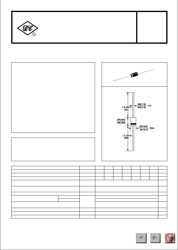
MECHANICAL DATA
* Case: Molded plastic
* Epoxy: UL 94V-0 rate flame retardant
* Mounting position: Any
* Weight: 1.18 grams
MAXIMUM RATINGS AND ELECTRICAL CHARACTERISTICS
Ratings at 25
o
C ambient temperature unless otherwise specified.
Single phase, half wave, 60 Hz, resistive or inductive load.
For capacitive load, derate current by 20%.
1N5400
THRU
1N5408
DO-27
NOTES : Measured at 1 MH
Z
and applied reverse voltage of 4.0 volts
Dimensions in inches and (millimeters)
at Rated DC Blocking Voltage
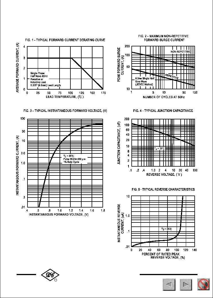
Maximum Full Load Reverse Current Average, Full Cycle
.375*(9.5mm) lead length at T
L
= 75
o
C
V
F
I
R
1.1
5.0
30
uAmps
uAmps
Maximum DC Reverse Current
Maximum Instantaneous Forward Voltage at 3.0A DC
Volts
@T
A
= 25
o
C
@T
A
= 100
o
C
500
Maximum Recurrent Peak Reverse Voltage
Maximum RMS Voltage
Maximum DC Blocking Voltage
Maximum Average Forward Rectified Current
.375*(9.5mm) lead length at T
L
= 105
o
C
Peak Forward Surge Current 8.3 ms single half sine-wave
superimposed on rated load (JEDEC Method)
Operating and Storage Temperature Range
SYMBOL
V
RRM
V
DC
I
O
I
FSM
T
J
, T
STG
V
RMS
Volts
Volts
Volts
Amps
3.0
200
-65 to + 175
Amps
0
C
UNITS
Typical Thermal Resistance
R
J A
30
0
C/ W
50
100
200
400
600
800
1000
70
35
140
280
420
700
560
50
200
400
600
800
1000
100
1N5400 1N5401 1N5402 1N5404 1N5406 1N5407 1N5408
* Lead: MIL-STD-202E, Method 208 guaranteed
* Polarity: Color band denotes cathode end
Typical Junction Capacitance (Note)
C
J
40
pF
112
NEXT
BACK
EXIT
NEXT
BACK
EXIT
NEXT
BACK
EXIT