FEATURES
* Low power loss, high efficiency
* Low forward voltage drop
* Low thermal resistance
* High current capability
* High speed switching
* High surge capability
* High reliability
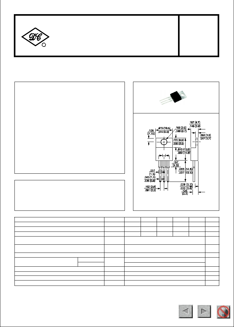
MECHANICAL DATA
MAXIMUM RATINGS AND ELECTRICAL CHARACTERISTICS
Ratings at 25
o
C ambient temperature unless otherwise specified.
Single phase, half wave, 60 Hz, resistive or inductive load.
For capacitive load, derate current by 20%.
* Case: Molded plastic
* Epoxy: UL 94V-0 rate flame retardant
* Lead: MIL-STD-202E, Method 208 guaranteed
* Mounting position: Any
* Weight: 2.24 grams
* Polarity: As marked
HER1601
THRU
HER1605
TO-220
Maximum Recurrent Peak Reverse Voltage
Maximum RMS Voltage
Maximum DC Blocking Voltage
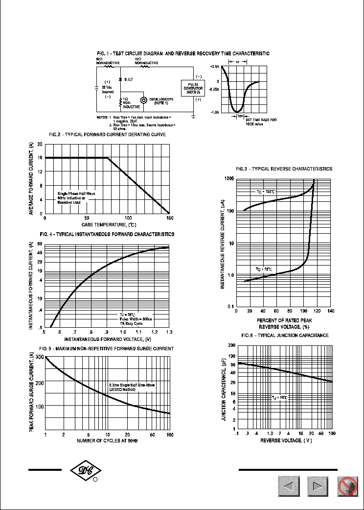
Maximum Average Forward Rectified Current
at T
C
= 75
o
C
Peak Forward Surge Current 8.3 ms single half sine-wave
superimposed on rated load (JEDEC Method)
SYMBOL
V
RRM
V
DC
I
FSM
V
RMS
UNITS
50
Volts
Volts
Volts
Amps
35
210
16
300
Amps
100
I
O
50
200
300
HER1601
HER1603
HER1605
HER1602
HER1604
200
400
70
280
400
100
at Rated DC Blocking Voltage
Maximum Reverse Recovery Time (Note 1)
V
F
I
R
nSec
uAmps
Maximum DC Reverse Current
Maximum Instantaneous Forward Voltage at 8.0A DC
Volts
10
60
@T
C
= 100
o
C
@T
C
= 25
o
C
trr
150
NOTES : 1. Test Conditions: I
F
= 0.5A, I
R
= 1.0A, I
RR
= 0.25A
2. Measured at 1 MHz and applied reverse voltage of 4.0 volts.
3. Suffix "A"= Common Anode.
Typical Thermal Resistance
Typical Junction Capacitance (Note 2)
C
J
T
J, TSTG
2.5
40
0
C/ W
0
C
Operating and Storage Temperature Range
R
J C
-65 to + 150
pF
TECHNICAL SPECIFICATIONS OF HIGH EFFICIENCY RECTIFIER
VOLTAGE RANGE - 50 to 400 Volts CURRENT - 16 Amperes
RECTIFIER SPECIALISTS
R
DC COMPONENTS CO., LTD.
Dimensions in inches and (millimeters)
300
140
1.1
72
NEXT
BACK
EXIT
NEXT
BACK
EXIT
NEXT
BACK
EXIT