RECTIFIER SPECIALISTS
R
DC COMPONENTS CO., LTD.
TECHNICAL SPECIFICATIONS OF SILICON RECTIFIER
VOLTAGE RANGE - 50 to 1000 Volts CURRENT - 2.0 Amperes
FEATURES
* Low cost
* Low leakage
* Low forward voltage drop
* High current capability
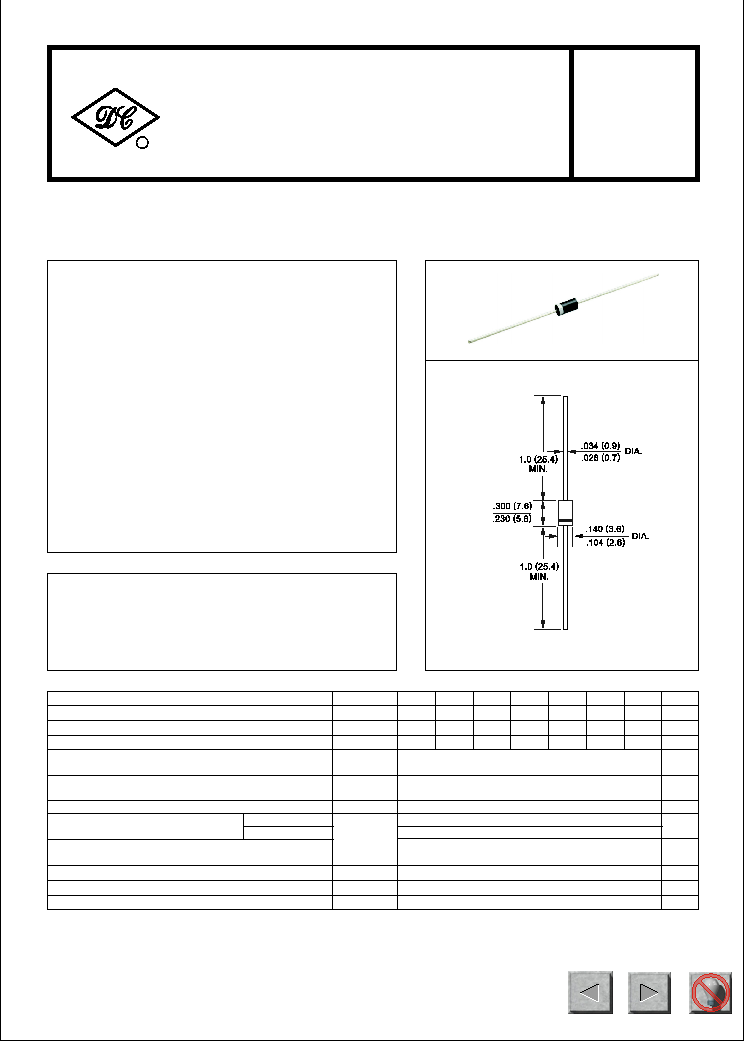
MECHANICAL DATA
* Case: Molded plastic
* Epoxy: UL 94V-0 rate flame retardant
* Mounting position: Any
* Weight: 0.38 gram
MAXIMUM RATINGS AND ELECTRICAL CHARACTERISTICS
Ratings at 25
o
C ambient temperature unless otherwise specified.
Single phase, half wave, 60 Hz, resistive or inductive load.
For capacitive load, derate current by 20%.
RL201
THRU
RL207
NOTES : Measured at 1 MH
Z
and applied reverse voltage of 4.0 volts
Dimensions in inches and (millimeters)
Maximum Recurrent Peak Reverse Voltage
Maximum RMS Voltage
Maximum DC Blocking Voltage
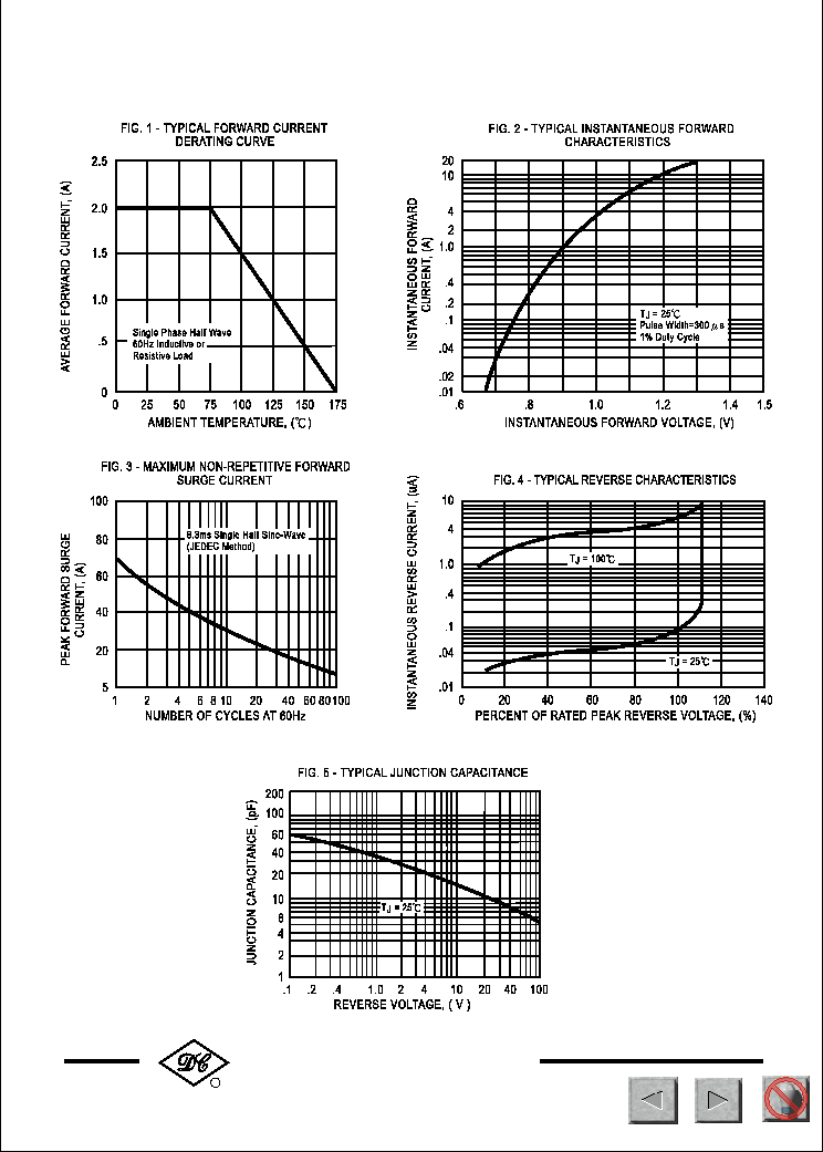
Maximum Average Forward Rectified Current
at T
A
= 75
o
C
Peak Forward Surge Current, 8.3 ms single half sine-wave
superimposed on rated load (JEDEC Method)
Operating and Storage Temperature Range
SYMBOL
V
RRM
V
DC
I
O
I
FSM
T
J
, T
STG
V
RMS
Volts
Volts
Volts
Amps
2.0
70
-65 to + 175
Amps
0
C
UNITS
Typical Thermal Resistance
R
J A
40
0
C/ W
50
100
200
400
600
800
1000
70
35
140
280
420
700
560
50
200
400
600
800
1000
100
RL201
RL202
RL203
RL204
RL205
RL206
RL207
at Rated DC Blocking Voltage
Maximum Full Load Reverse Current Average, Full Cycle
o
V
F
I
R
1.1
5.0
30
uAmps
uAmps
Maximum DC Reverse Current
Maximum Instantaneous Forward Voltage at 2.0A DC
Volts
@T
A
= 25
o
C
@T
A
= 100
o
C
500
DO-15
* Lead: MIL-STD-202E, Method 208 guaranteed
* Polarity: Color band denotes cathode end
Typical Junction Capacitance (Note)
C
J
20
pF
.375*(9.5mm) lead length at T
L
= 75 C
110
NEXT
BACK
EXIT
NEXT
BACK
EXIT
NEXT
BACK
EXIT