TECHNICAL SPECIFICATIONS OF SURFACE MOUNT ULTRA FAST RECTIFIER
VOLTAGE RANGE - 50 to 800 Volts CURRENT - 2.0 Amperes
MAXIMUM RATINGS AND ELECTRICAL CHARACTERISTICS
Ratings at 25
o
C ambient temperature unless otherwise specified.
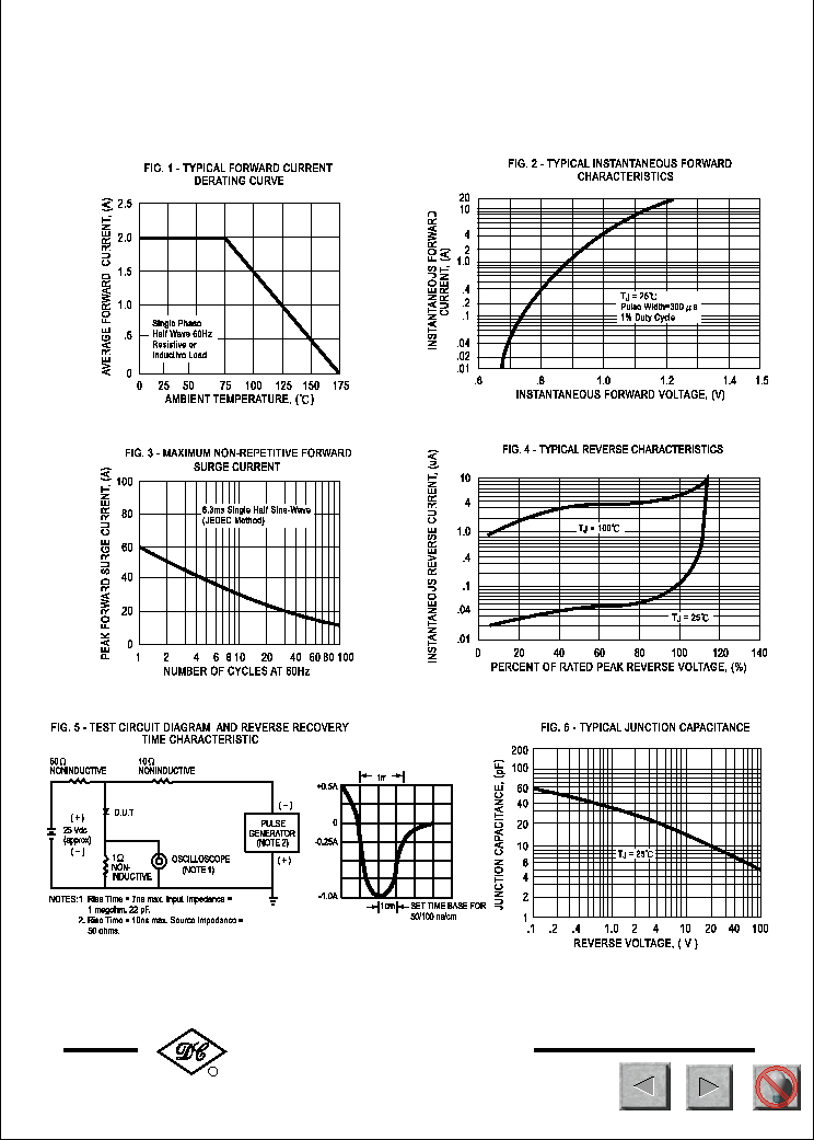
Single phase, half wave, 60 Hz, resistive or inductive load.
For capacitive load, derate current by 20%.
UF2A
THRU
UF2K
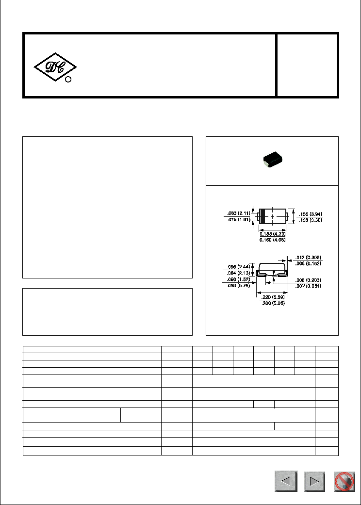
SMB ( DO-214AA)
Dimensions in inches and (millimeters)
Maximum DC Reverse Current
at Rated DC Blocking Voltage
V
F
I
R
uAmps
Maximum Instantaneous Forward Voltage at 2.0A DC
Volts
10
200
@T
A
= 25
o
C
@T
A
= 100
o
C
1.0
Maximum Recurrent Peak Reverse Voltage
Maximum RMS Voltage
Maximum DC Blocking Voltage
Maximum Average Forward Rectified Current
at TA = 75 C
Peak Forward Surge Current 8.3 ms single half sine-wave
superimposed on rated load (JEDEC Method)
Typical Thermal Resistance (Note 2)
SYMBOL
V
RRM
V
DC
I
FSM
T
J,
T
STG
V
RMS
UNITS
Volts
Volts
Volts
Amps
2.0
60
20
Amps
0
C/ W
pF
Operating and Storage Temperature Range
I
O
30
Typical Junction Capacitance (Note 1)
C
J
-65 to + 175
0
C
R
JL
o
RECTIFIER SPECIALISTS
R
DC COMPONENTS CO., LTD.
FEATURES
* Glass passivated junction
* ldeal for surface mounted applications
* Low leakage current
MECHANICAL DATA
* Case: Molded plastic
* Epoxy: UL 94V-0 rate flame retardant
* Mounting position: Any
* Weight: 0.093 gram
*Terminals: Solder plated, solderable per
MIL-STD-750, Method 2026
* Polarity: As marked
UF2A UF2B UF2D UF2G UF2J UF2K
50 100 200 400 600 800
35 70 140 280 420 560
50 100 200 400 600 800
Maximum Reverse Recovery Time (Note 3)
trr
nSec
50
1.4
1.7
100
NOTES : 1. Measured at 1 MHz and applied reverse voltage of 4.0 volts.
2. Thermal Resistance (Junction to Ambient), 0.2x0.2in (5X5mm )
2
copper pads to each terminal.
3. Test Conditions: IF=0.5A, IR=1.0A, IRR=0.25A.
2
328
NEXT
BACK
EXIT
NEXT
BACK
EXIT
NEXT
BACK
EXIT