
Preliminary
DLBM-CG121
Data Sheet
July 30, 2004
Proprietary Information and Specifications are Subject to Change
DLBM-CG121
Bluetooth Module Class 2
A Class 2 Bluetooth module suitable
for cellular phone, smart phone
applications.
1.FEATURES:
Support DUN, SPP, AG & FAX profiles.
Minimal software effort to own Bluetooth functions.
Almost no resource required from host CPU.
Reducing the size and thickness greatly by using high-density
packaging technology.
Compliant to various interfaces: UART, USB, PCM ...etc.
Wide operating temperature range: -30~+80
.
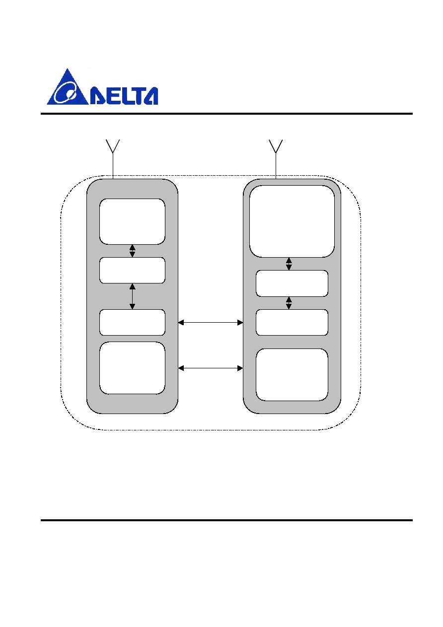
2.Device diagram
Figure 1. DLBM-CG121 Block Diagram
TM
TM
BC 3-H andphone

Preliminary
DLBM-CG121
Data Sheet
July 30, 2004
Proprietary Information and Specifications are Subject to Change
3.General Specification
Bluetooth Specification
Version 1.1
Frequency
2402~2480MHz
Modulation
FHSS/GFSK
Transmission rate
721kbps
Receive sensitivity
-80dBm
Maximum output power
+4dBm(Class 2)
Operating Voltage
1.8V or 2.2~3.6V
Operating temperature
-30~+80
Antenna Impedance
50 ohm
Package size
9.1*7.9*1.6mm
Operating range
> 10 meters
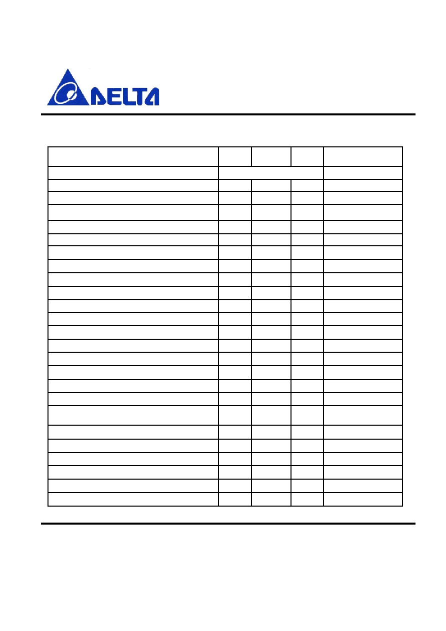
4.Rating
Min
Max
Unit
Storage Temperature
-40 +85
VDD_1.8V
-0.4 +1.9
V
VDD_IO
-0.4 +3.6
V
VREG_IN
-0.4 +3.6
V
TM

Preliminary
DLBM-CG121
Data Sheet
July 30, 2004
Proprietary Information and Specifications are Subject to Change
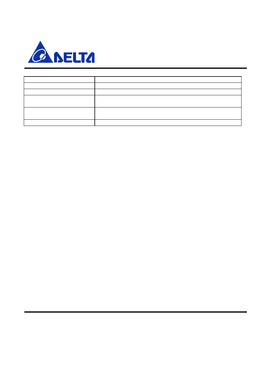
5.Interface
Interface Description
Antenna
External Antenna 50 ohm
UART Interface
TX,RX,RTS,CTS(9600bps~1.5Mbps)
SPI Interface
Synchronous Serial Interface for firmware download
PIO Interface
8 terminals
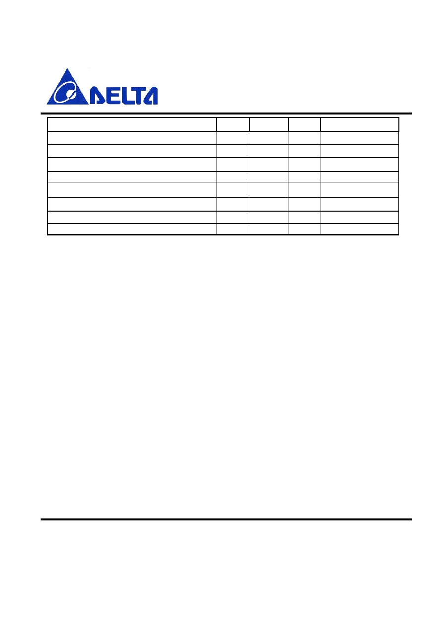
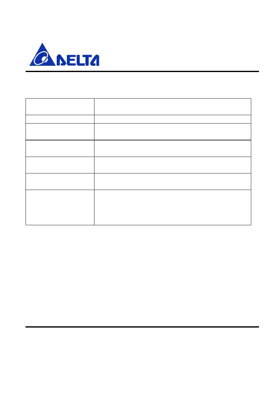
6.Power Supply Diagram
Figure 2. Power Supply Diagram
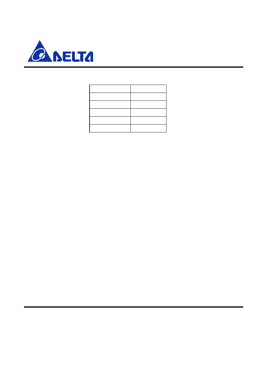
Terminal
3.0V Power Supply
1.8V Power Supply
VDD_1.8V
NC
1.7 to 1.9V
VDD_IO
1.7 to 3.6V
1.7 to 1.9V
VREG_IN
2.2 to 3.6V
NC
A N T
X 'tal
BPF
V D D _1.8V
BC 2-R O M
V D D _IO
V R EG _IN
Balun
Preliminary
DLBM-CG121
Data Sheet
July 30, 2004
Proprietary Information and Specifications are Subject to Change
7.RF Characteristics
Operating Condition: +25, VDD=1.8V
RF Characteristics
Min.
Typ.
Max.
Unit
1. Frequency Range
2400 ~ 2483.5
MHz
2. Output Power
0
4
dBm
3. Sensitivity at 0.1% BER
1) 2402MHz
-80
dBm
2) 2441MHz
-80
dBm
3) 2480MHz
-80
dBm
4. Maximum Input Level (BER0.1%)
3
dBm
5. Adjacent channel selectivity
1) C/I F=F
0
+ 1MHz
-4
0
dB
2) C/I F=F
0
- 1MHz
-4
0
dB
3) C/I F=F
0
+ 2MHz
-35
-30
dB
4) C/I F=F
0
- 2MHz
-21
-20
dB
5) C/I FF
0
+ 3MHz
-45
dB
6) C/I FF
0
- 5MHz
-45
dB
7) C/I F=F
Image
-18
-9
dB
6. Adjacent channel transmit power
1) F=F
0
� 2MHz
-35
dBc
2) F=F
0
� 3MHz
-55
dBc
7. Modulation Characteristics
1) Modulation f1avg
165
kHz
2) Modulation f2max
155
-
kHz
8. Initial Carrier Frequency Tolerance
1) 2402MHz
-75
-3
75
kHz
2) 2441MHz
-75
-7
75
kHz
3) 2480MHz
-75
-14
75
kHz
Preliminary
DLBM-CG121
Data Sheet
July 30, 2004
Proprietary Information and Specifications are Subject to Change
9. Carrier Frequency Drift
1) 1slot
9
kHz
2) 5slot
10
kHz
4) Drift rate
8
KHz/50us
10. 20dB Bandwidth for modulated carrier
1) 2402MHz
879
KHz
2) 2441MHz
816
KHz
3) 2480MHz
819
KHz
11.C/I co - channel
9
dB
Preliminary
DLBM-CG121
Data Sheet
July 30, 2004
Proprietary Information and Specifications are Subject to Change
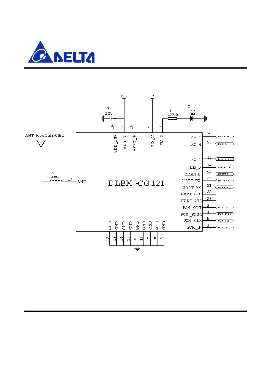
8.Application circuit
Figure 3. 1.8V Supply
Preliminary
DLBM-CG121
Data Sheet
July 30, 2004
Proprietary Information and Specifications are Subject to Change
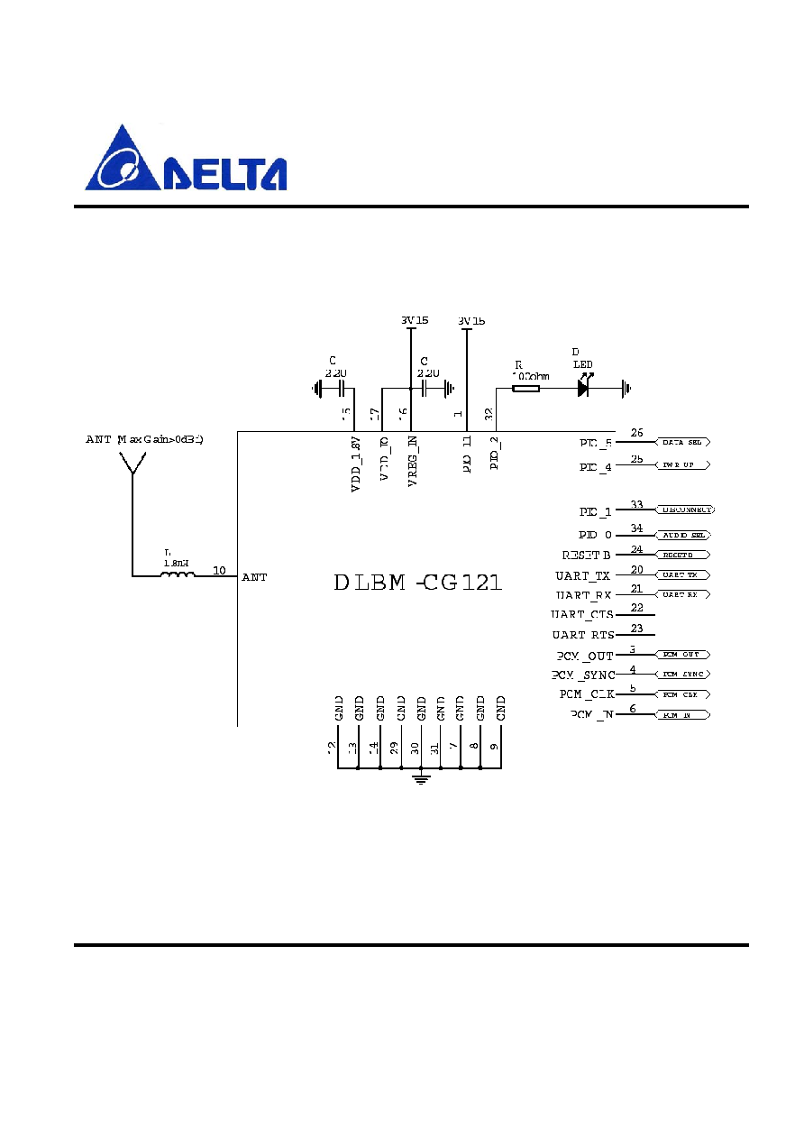
Figure 4. 2.2~4.2V Supply

Preliminary
DLBM-CG121
Data Sheet
July 30, 2004
Proprietary Information and Specifications are Subject to Change
9. PIO Setting
� AUDIO_SEL and DATA_SEL � hardware signal profile identifier
� PWR_UP � used as a wake up pulse before UART communications
� DISCONNECT SIGNAL � hardware RFComm disconnect input
� PIO[11] 16MHz clock select
� PIO[2] LED display
Preliminary
DLBM-CG121
Data Sheet
July 30, 2004
Proprietary Information and Specifications are Subject to Change
10. Basic Embedded Architecture
11.Hardware connection
DLBM-CG121 requires the following hardware connections:
Serial communications port with or without hardware flow control.
PCM interface for audio gateway profile.
H O ST
D LBM -C G 121
MMI
AT interpreter
UART
Digital Audio
Profiles
Audio Gateway
Dial-up Networking
Serial Port
FAX
AT interpreter
UART
Digital Audio
AT C om m ands
PC M
Figure 5. Embedded Architecture
BTM

Preliminary
DLBM-CG121
Data Sheet
July 30, 2004
Proprietary Information and Specifications are Subject to Change
12. Mobile Phone Host requirements
The DLBM-CG121 is designed to connect to the existing audio and data connections which
or almost always made available on any mobile phone. This removes the need for any
baseband software modifications on the part of the host controller since these connections
already exist.
The mobile phone designer need simply design a Bluetooth Man-Machine interface in order to
do the following functions:
Bluetooth Neighborhood inquiry
Select, enter PIN and pair with a remote device
Show the status of a currently connected Bluetooth service.
Limited control of the Bluetooth link i.e. SCO creation (automatic option also available),
in-band / out-of band ring determination etc.
Since all the profiles are handles on DLBM-CG121 and a simple AT command set is
utilized, there is minimal effort and time to market for the mobile phone company.
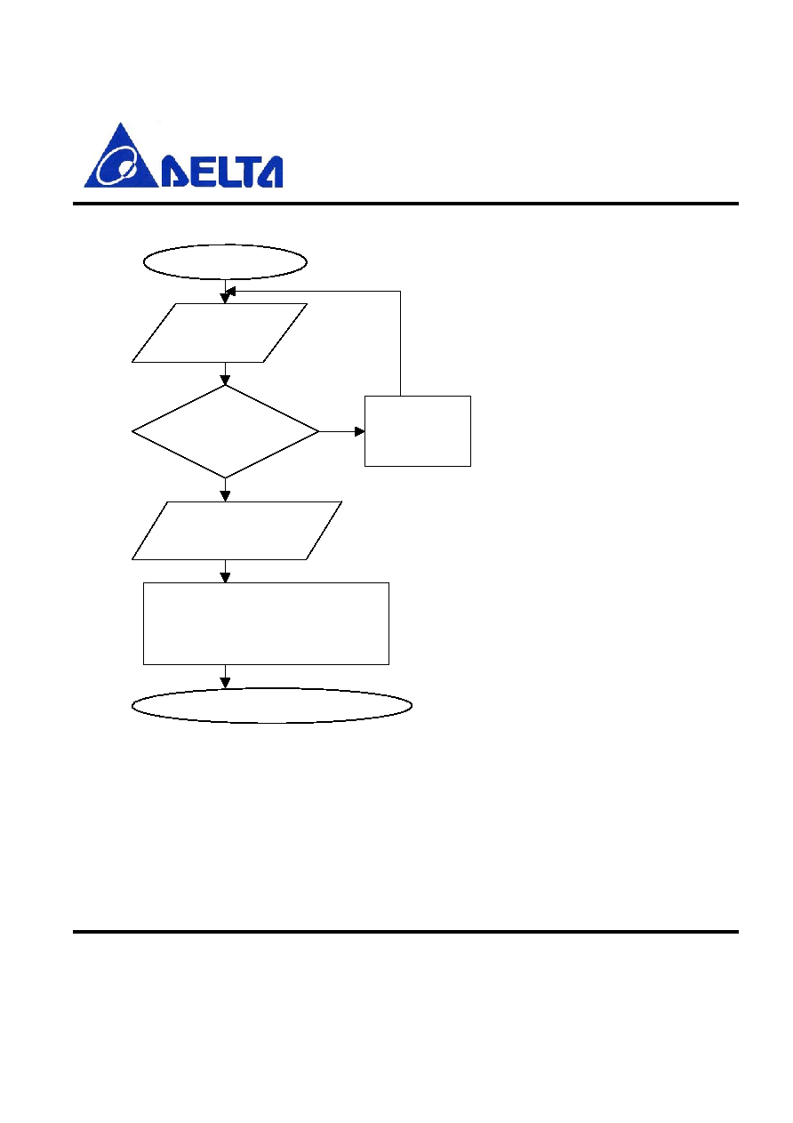
13. Software architecture
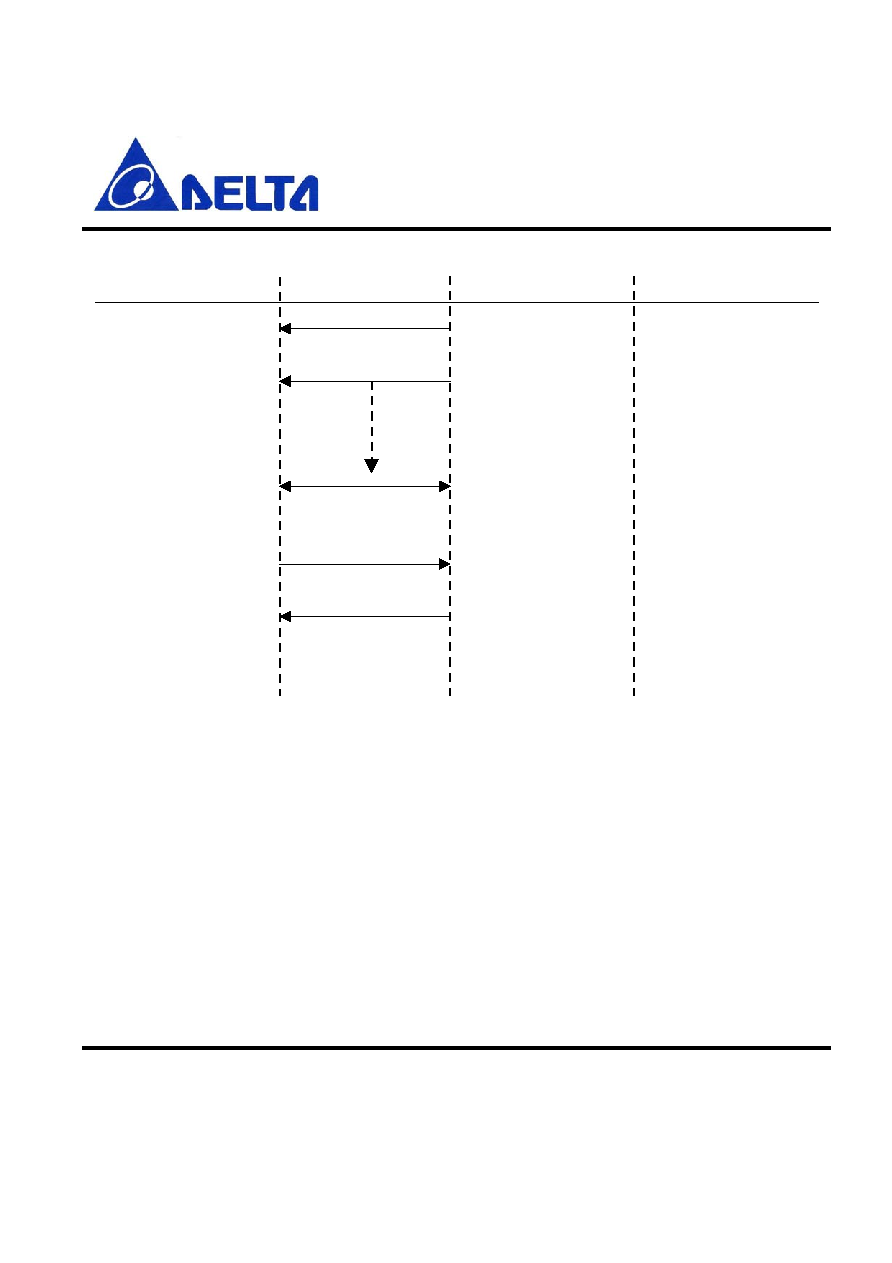
13.1 Initialization and start-up
When DLBM-CG121 is initially turned on, the DLBM-CG121 firmware will request
configurations data from the host using the +CCFG command. The host will download the
PSKEYS, Bluetooth address and friendly name at this point and when it has finished
configuring the device, will initiate a warm reset via the BCCMD interface.
Preliminary
DLBM-CG121
Data Sheet
July 30, 2004
Proprietary Information and Specifications are Subject to Change
ATEO
"O K " Received?
D elay 1s
Request configuration
from host (+CCFG )
Figure 6. Software Architecture
RESET
H ost sets up supported profiles list,
Bluetooth address, friendly nam e
and other required PSK EY S
H ost initiates w arm reset via BCCM D
N o
Yes

Preliminary
DLBM-CG121
Data Sheet
July 30, 2004
Proprietary Information and Specifications are Subject to Change
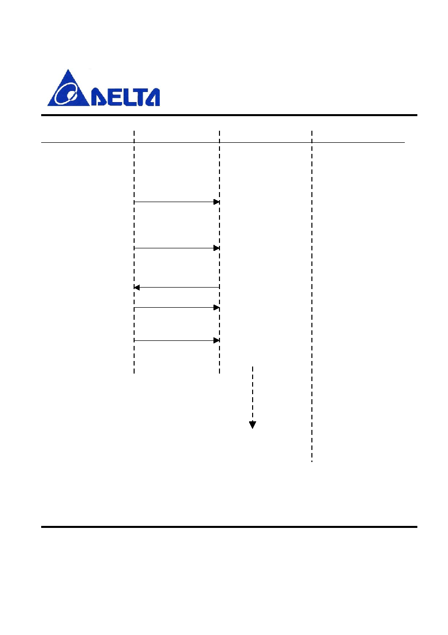
13.2 Setting PSKeys
Setting the PSKEYS consist of three elements in the AT+SETPS command. These elements
are:
The Pskey address which is a four digit word formatted in ASCII that represents the
address of the key to be set. Therefore, to change the contents of address 0x0108, this
field will be set to "0108".
The data string which is made up of multiples of four digit words. These word will be filled in
the respective PSKey address's data field. E.g. "000112349876" will enter the word 0001
1234 9876 into the selected PSKEY.
The store type. Typically this should be set to 8 to select the Ram are of PSKEYS.
An example of setting the PSKEYS is to set the crystal frequency trim :-
AT+SETPS=01f6,001d,0008.
To set a string value such as the friendly name, the host must prefix the data field with `s' i.e.
AT+SETPS =0108,sHandphone,0008. This will change the friendly name to "Handphone"
To read a PSKEY, the host must use the AT+GETPS command e.g. AT+GETPS=01f6 will
return the crystal frequency trim value.
To initiate a warm reset, the host must use the BCCMD protocol using the varid 0x4002 e.g.
AT+BCCMD=4002,0002,0000.
One of the field that must be set is the supported profiles list or PSKey address 0x028d

Preliminary
DLBM-CG121
Data Sheet
July 30, 2004
Proprietary Information and Specifications are Subject to Change
13.3 Supported profiles list (0x028d)
During the configuration process, the host must set up the supported profile list in
PSKEY_USR_3 as follows:
Bit 7
Bit 6
Bit 5
Bit 4
Bit 3
Bit 2
Bit 1
Bit 0
Reserved Reserved Reserved Fax Handsfree
DUN
SPP
Headset
Setting the respective bit will cause this profile to be registered after the warm reset.
Phone Event
DLBM-CG121 Event
Set Bluetooth
address
Set friendly nam e
Start Initialization
Set Bluetooth address
Set friendly nam e
Set other required
PSK EY S
Initiate w arm reset
D LBM -CG 121 reset w ith
new values in RA M
+CCFG
AT+SETPS=0001,<bd,addr>,0008
O K
AT+SETPS=0108,s<nam e>,0008
O K
AT+SETPS=<key>,<data>,0008
O K
AT+BCCM D =4002,0002,0000
Preliminary
DLBM-CG121
Data Sheet
July 30, 2004
Proprietary Information and Specifications are Subject to Change
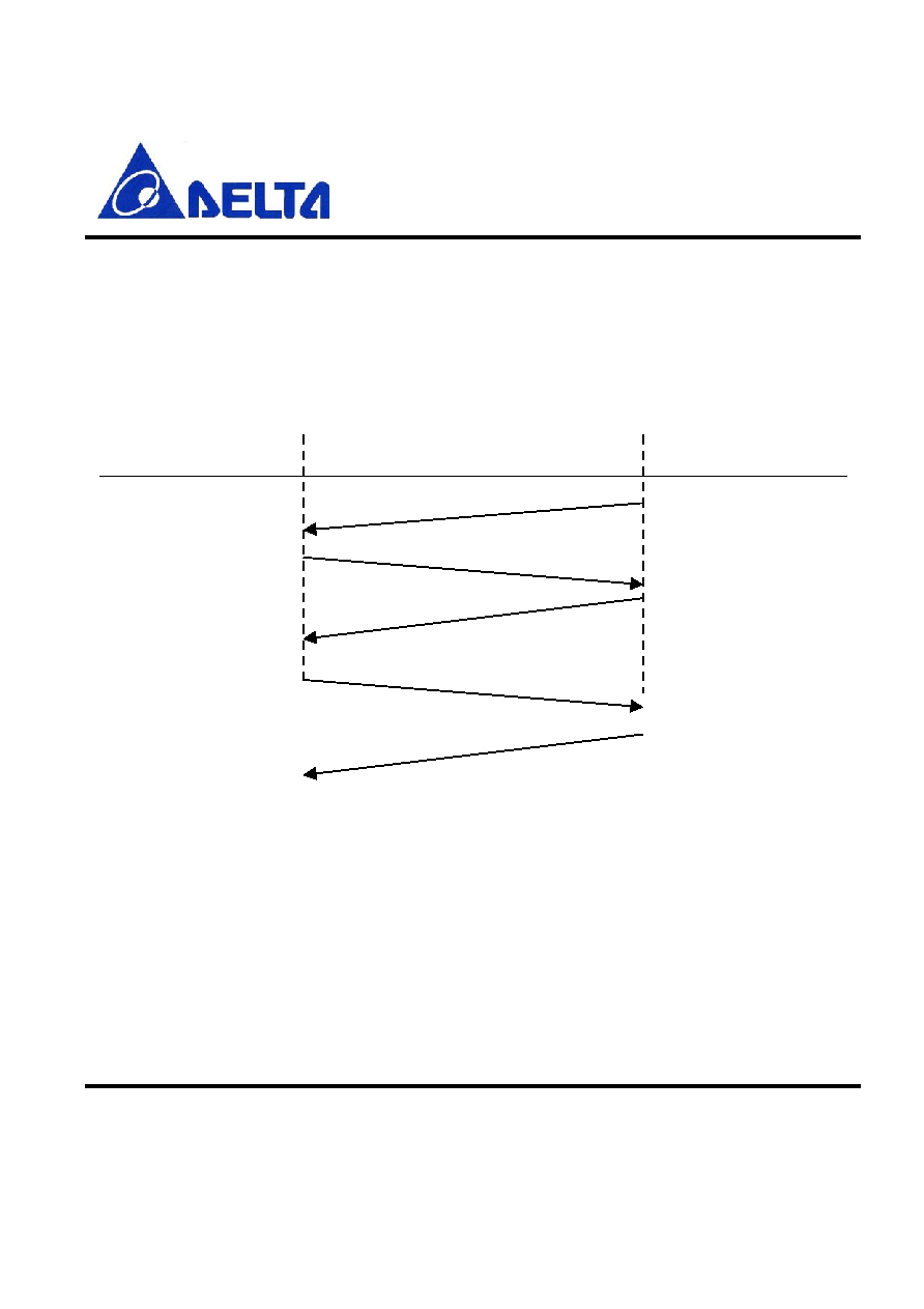
13.4 Device Registration process
Once the configuration process has completed, and the warm reset has been initiated, the host
must register the trusted devices with the firmware. The host can register devices at any time
after the DLBM-CG121 as sent the +CRREG request command. Once the device registration
command has been sent from the host, the host must wait for the OK response from the
DLBM-CG121 before registering the next device.
Phone Event
DLBM-CG121 Event
Retrieve first
trusted device
Retrieve trusted
device n
Initialization com pleted
Register bd_addr[0]
w ith link key[0]
Register bd_addr[n]
w ith link key[n]
+CRREG
AT+CREG =<bd_addr[0]>,<link key[0]>
O K
AT+CREG =<bd_addr[n]>,<link key[n]>
O K
Preliminary
DLBM-CG121
Data Sheet
July 30, 2004
Proprietary Information and Specifications are Subject to Change
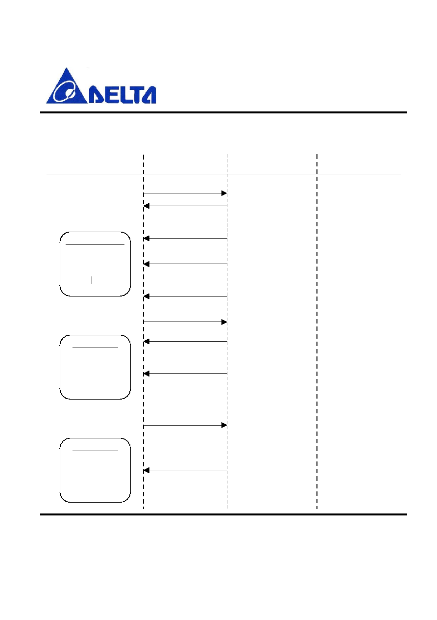
13.5 Pairing Process
The sequence to pair the DLBM-CG121 with external remote devices is done as follows:
M obile Phone H ost
U A R T
D LBM -C G 121 C om m ents
Search BT N eighborhood
AT+CIQ R = (1, 2),(1-8)
O K
Start Inquiry
1- A udio D evices
2-
A ll D evices
1-8 � no of returns
D evices Found
N am e 1
N am e 2
N am e 5
+CIN Q RES = nam e 1 ,
bd_addr 1
Inquiry Result indication Receive responses
Select a device e.g nam e 2
N am e 2
PIN : ****
U ser enters the PIN code
1234
N am e 2
N am e 2 paired
successfully
AT+CPRR = bd_addr 2
O K
+CPIN REQ = bd_addr 2
AT+CPCR = bd_addr 2, 1234
+CPIN CFM = (0 - 4),
<link_key>
Starts Paring process
w ith bd_addr 2
A sk for PIN from host
D LBM -CG 121 sends the
PIN code to the rem ote
device
D LBM -CG 121 sends the
result of the paring
process to the host
Rem ote device
request a PIN code
If PIN is correct
pairing successful
otherw ise failure
+CIN Q RES = nam e 2 ,
bd_addr 2
+CIN Q RES = nam e n ,
bd_addr n

Preliminary
DLBM-CG121
Data Sheet
July 30, 2004
Proprietary Information and Specifications are Subject to Change
A "+CINQCFM=<status> message will be sent to the host indicating why an inquiry is finished.
This may be due to inquiry cancellation (e.g. when the user selects a device in the middle of an
inquiry), Inquiry complete when the inquiry timer has expired, or maximum number of
responses has been received.

Preliminary
DLBM-CG121
Data Sheet
July 30, 2004
Proprietary Information and Specifications are Subject to Change
13.6 Incoming call is received (out-of-band ring used)
M obile Phone H ost
U A R T
D LBM -C G 121
C om m ents
Handphone will attempt a
connection
Connect request with
device bd_addr
Connect request
to headset
AT+CCMR=<bd_addr>
, 1,1
Bluetooth connection
established
Headset Profile
Incoming Call
Call answered
+CRFCSTAT=bd_addr,0
RFComm connection
established
+CPROFILE = 1
RING
Send Ring command
Headset plays ring
sequence
+CKPD=200
DLBM-CG121 can
answer automatically
(PSKEY_USR11 : 8)
User answers call
If +CKPD = 200 then
ask for SCO
DLBM-CG121
establishes a HV3 SCO
connection
Audio path open
+CSCOSTAT=0
DLBM-CG121 indicates
SCO
Call Disconnected
+CKPD=200
DLBM-CG121 receives
AT+CKPD = 200
command
AT+CASR=0
User disconnects call
Phone indicates call
disconnection
NO CARRIER
DLBM-CG121 removes
SCO connection
Audio lost
+CSCOSTAT=3

Preliminary
DLBM-CG121
Data Sheet
July 30, 2004
Proprietary Information and Specifications are Subject to Change
Phone disconnects
RFComm connection
+CRFCSTAT=bd_addr,3
RFComm link lost
AT+CRDR
DLBM-CG121 removes
RFC connection
Phone Disconnected

Preliminary
DLBM-CG121
Data Sheet
July 30, 2004
Proprietary Information and Specifications are Subject to Change
13.7 Incoming call is received (in-band ring used)
M obile Phone H ost
U A R T
D LBM -C G 121
C om m ents
Incoming Call
AT +CCMR=bd_addr,1,1
Connect request with
bd_addr
DLBM-CG121 will attempt
a connection unless a
service level connection
already exists
Bluetooth connection
established
+CRFCSTAT=bd_addr,0
RFComm connection
established
Headset profile
+CPROFILE=1
Incoming Call
RING
DLBM-CG121 opens
audio path
Audio path open Headset
plays in band ring tone
from phone
+CSCOSTAT=0
DLBM-CG121
indicates SCO status
Call answered
+CKPD=200
DLBM-CG121 indicates
button press
User answers call
Call Disconnected
+CKPD=200
DLBM-CG121 receives
AT+CKPD = 200
command
User disconnects call
Phone indicates call
disconnection
NO CARRIER
DLBM-CG121 removes
SCO connection
Audio lost
Bluetooth connection
lost e.g. out of range
+CSCOSTAT=3
+CRFCSTAT=bd_addr,3
Example of user goes
out of range
RFComm link lost

Preliminary
DLBM-CG121
Data Sheet
July 30, 2004
Proprietary Information and Specifications are Subject to Change
13.8 Data services
The DLBM-CG121 supports the following data services
Serial Port Profile (+CPROFILE = 2)
Dial-up networking (+CPROFILE = 3)
Handsfree Profile (+CPROFILE = 4)
Fax (+CPROFILE = 5)
The default state of the firmware is to always be in idle. Therefore to put the device into
connectable mode, the host must issue the AT+CCSR command.
On connection of a service from a remote devices, the firmware will indicate the status of the
service level connection with +CRFCSTAT = <bd_addr>,0. Thereafter the service type will be
indicated with +CPROFILE=<service>.
At this point, DLBM-CG121 will route all traffic passing over the RFComm layer directly to the
UART and vice versa. Therefore, all "Fone Suite" applications will run over the serial port profile
allowing the use of features such a sync, SMS, calendar etc over Bluetooth.
Dial-up networking and fax operations will also directly route the RFComm traffic over UART,
therefore all modem settings for the mobile phone will be configured on the remote device
configuration settings.
When a service is disconnected, DLBM-CG121 will indicate the removal of the service level
connection with +CRFCSTAT=<bd_addr>,3.
Preliminary
DLBM-CG121
Data Sheet
July 30, 2004
Proprietary Information and Specifications are Subject to Change
13.9 SPP, DUN and Fax connections
When the Dial-up Networking, SPP or FAX profiles are activated, DLBM-CG121 will initiate two
actions:
�
Change the mode state hardware output according to the setting is PSKEY_USR18. It will
also issue the data stored in PSKEY_USR32 (SPP service connected), PSKEY_USR33 (DUN
service connected) or PSKEY_USR35 (Fax service connected) which may be required by
certain mobile phones to switch modes.
�
Immediately create a direct link between the UART data and RFComm data. At this point, the
DLBM-CG121 is not involved in any data between the two devices.
M obile Phone H ost U A
R T
D LBM -C G 121
C om m ents
Bluetooth connection
established
+CRFCSTAT=bd_addr,0
RFComm connection
established
SPP,Dial-up or Fax
service connects to
D LBM -CG 121
SPP,DUN,Fax Profile
+CPROFILE=(2,3,5)
Start 200ms timer to
flush buffers
RFComm traffic routed
directly to UART and
vice versa
D LBM -CG 121
does not
process any commands
Direct communications
with remote device
RFComm Disconnect
Request
PAIR I/O momentarily
pulled high to
disconnect RFComm
RFCom m disconnected
Remote user disconnects
service
UART data now available
to
D LBM -CG 121
Bluetooth connection
lost
+CRFCSTAT=0.3

Preliminary
DLBM-CG121
Data Sheet
July 30, 2004
Proprietary Information and Specifications are Subject to Change
On disconnection of the RFComm link, the mode state hardware output will change to the
default mode and issue the data stored in PSKEY_USR30
To ensure that the mobile phone does indeed disconnect on the loss of an RFComm link,
PSKEY_USR36 can be used to store the text string that will unconditionally disconnect the
phone from the network (e.g +++ATH\r). An alternative method is to use the DATA_SEL I/O
which will invert state for a period of 1s after the RFComm link has been lost. This can be used
to simulate disconnection of a data service.
For the list of DUN and FAX commands, refer to DUN and FAX profile specification from the
Bluetooth SIG.
13.10 Changing the default states of BlueCore2/3-Gateway
It is possible to change the default states to the following:
�
Make DLBM-CG121 idle. This is accomplished by sending the AT+CCNR command. This will
cancel the last operation and switch off the BlueCore radio.
�
Make DLBM-CG121 discoverable. This is accomplished by sending the AT+CDIS= <use
authentication> command to BlueCore. This will set-up a page and inquiry scan process so that
the device is discoverable and connectable to other Bluetooth devices. This has the
disadvantage of increasing the power consumption of DLBM-CG121. If Use Authentication is
set then the DLBM-CG121 will request a PIN on first connection to the remote device.
�
Make DLBM-CG121 connectable. This is accomplished by sending the AT+CCSR=<use
authentication> command to device. This will set-up a page scan process only so that the
device is only connectable to other Bluetooth devices which know it's address already. If Use
Authentication is set then the firmware will request a PIN on first connection to the remote
device.

Preliminary
DLBM-CG121
Data Sheet
July 30, 2004
Proprietary Information and Specifications are Subject to Change
�
You can restart the DLBM-CG121 software by sending a AT+CRST command. This causes
the software to panic and then relies on the watchdog timer to reset the device.

Preliminary
DLBM-CG121
Data Sheet
July 30, 2004
Proprietary Information and Specifications are Subject to Change
13.11 Using Low Power Modes with the AT command set
Since the standard UART protocol does not allow for the retry of transmission when information
is lost over the UART, DLBM-CG121 uses a specific set off instructions to cause the device to
exit out of deep sleep.
The software recognises the AT command "AT+CWUP" from the host and will respond with a
" WAKEOK= <expected minimum wakeup time". Therefore the host can issue the AT+CWUP
command repetitively until it receives the WAKEOK command response. The parameter which
is associated with the response, indicates the minimum time that the DLBM-CG121 will be
awake and is sent in millisecond units. Therefore the host does not have to send AT+CWUP
commands during this period. To reduce latencies, it is possible to re-transmit the second
AT+CWUP command within 100ms of the first AT+CWUP command since there will be a high
probability that DLBM-CG121 would now be awake. Thereafter it is suggested to wait at least
5000ms between subsequent AT+CWUP commands in order for DLBM-CG121 to respond.
Preliminary
DLBM-CG121
Data Sheet
July 30, 2004
Proprietary Information and Specifications are Subject to Change
M obile Phone H ost U A
R T
D LBM -C G 121
C om m ents
Host wishes to send
a command to
D LBM -CG 121
.
D LBM -CG 121
is in
deep sleep
Communications causes
D LBM -CG 121
to exit deep
sleep with corrupt data in
the Uart. Timer starts to
keep
D LBM -CG 121
awake
It is not sure if
D LBM -CG 121
is able
to receive
AT+CWUP
D LBM -CG 121
is in
shallow sleep
No Response so
resend Wakeup
command
AT+CWUP
D LBM -CG 121
decodes
Wakeup Command
and starts 500mS
wakeup timer
WAKEOK=500ms
Host can now send
command within
500mS
AT+XXXX
D LBM -CG 121
restarts
5000mS timer on each
UART event
Host sends next
command within the
5000mS period
AT+XXXX
D LBM -CG 121
restarts
5000mS timer on each
UART event
5000mS expires.
D LBM -CG 121
may
now enter deep sleep
Preliminary
DLBM-CG121
Data Sheet
July 30, 2004
Proprietary Information and Specifications are Subject to Change
13.12 Improving Execution Time
It is possible to improve the execution time for known events by setting flags in PSKEY_USR11
as follows:
PSKEY_USR11 (Bit
Position)
Function
0-5 Reserved
6
Automatically connect SCO on receipt of ATA from Handsfree
device
7
Automatically disconnect SCO on receipt of AT+CHUP from
Handsfree device
8
Automatically connect SCO on receipt of AT+BVRA=1 from
Handsfree device
9
Automatically connect SCO on receipt of AT+CKPD=200 from
Headset device
10
Automatically connect SCO on receipt of +CIEV:<call>,1 from
host and
Automatically disconnect SCO on receipt of +CIEV:<call>,0 from
host
13.13 Hands Free Operation
In order for hands free to work correctly there must be a serial link to the GSM phone supporting
the GSM07.07 generic commands for hands free operation. These include the following:
ATA
AT+CHUP
ATDdd..dd;
ATD>nnn;
AT+CCWA
+CCWA
AT+CHLD
AT+CIND=?

Preliminary
DLBM-CG121
Data Sheet
July 30, 2004
Proprietary Information and Specifications are Subject to Change
AT+CIND?
AT+CLIP
+CLIP
AT+CMER
+CIEV
The above commands are not interpreted by DLBM-CG121 and rely on the mobile phone to
respond to these messages. All responses are passed directly to the hands free kit.
All other operation relating to service level connection and Bluetooth operation is handled by
DLBM-CG121
. In handset mode, some of these commands will be passed to the phone host for
interpretation such as AT+BVRA = <n> for voice recognition activation and AT+NREC=<n> for
noise cancellation request.
13.13.1 Bluetooth Hands Free Profile
The Bluetooth Hands Free profile is a mixture of analogue and data services. On connection of
a Hands Free kit to the phone, the mode state will be Audio. Therefore a phone not supporting
audio and data services simultaneously will not be able to support Bluetooth Hands free
operation.
The majority of commands used by the Hands Free profile are based on the GSM07.07 AT
command set. For all these commands,
DLBM-CG121
firmware will simply act as a feed through
for the commands and responses. Therefore, commands such as CMER, CIND, ATA,
AT+CHUP, ATD etc are not issued by
DLBM-CG121
but by the Hands Free kit.
It is still possible, however, to add more functionality to the Bluetooth hands free profile by
emulating some of the Bluetooth commands into a mode that the phone supports, e.g.
AT+BVRA=1 would initiate a voice tag dial in a Bluetooth phone.
In order to set up the supported features list to be sent with the SDP record, PSKEY_USR7
stores the Supported Features list in the same order as expected by the Hands Free Profile i.e.
Preliminary
DLBM-CG121
Data Sheet
July 30, 2004
Proprietary Information and Specifications are Subject to Change
PSKEY_USR7(Bit Position) Function
0 Three
way
calling
1
Echo cancellation or noise reduction (Unlikely to be supported)
2
Voice Recognition Function (is enabled will cause
DLBM-CG121
to initiate a long pulse sequence)
3
In-Band Ring Tone. (If enabled will force an Audio SCO
Connection on incoming calls)
4
Attach phone number to tag (Not supported)
13.14 Managing the Trusted Device List
Support has been included to manage the trusted device list. The commands associated with
this process are as follows:
Registering trusted devices stored within the host. This is done after DLBM-CG121 requests
registration of these devices using +CRREG command. The host can then register the devices
at any time, keeping in mind that any device not registered, attempting to connect with the
Handphone would require authentication.
Therefore, If a device is not a registered device, DLBM-CG121 will go through the process of
requesting a PIN, and if successful, will respond with the +CLINK=<bd_addr>,<link key>
response to inform the host of the new devices' link key and address. It would be up to the host
to decide whether to add this device to it's trusted device list or not.
Once the device have been registered, they may be removed from DLBM-CG121 security
manager by issuing the AT+CTDDEL = <bd_addr> command. This Bluetooth address will
thereafter be deleted from the registry.
The management of the trusted device list is kept within the host, therefore the host may decide
how many trusted devices to hold, and may change the name of the remote device name if so
required.

Preliminary
DLBM-CG121
Data Sheet
July 30, 2004
Proprietary Information and Specifications are Subject to Change
13.15 Initiating Connections
It is possible for the host to initiate a connection to a device as follows:
13.15.1 Devices found during inquiry
After completion of inquiry search, a list of devices will have been sent to the host using
"+CINQRES=<name>,<Bluetooth address>". It is possible to connect directly to a device
without pairing by issuing the command AT+CMMR=Bluetooth address,<authentica>, <profile>.
If authenticate is set then DLBM-CG121 will expect a pin code to be issued during the
connection process therefore to establish an un-secure connection, the authenticate field must
be set to 0 for unauthenticated connections.
The service you wish to connect to will be put into <Profile> as follows:
1 � Headset Profile
2 � Serial Port Profile
3 � Dial-up Network Profile
4 � Hands free profile
5 � Fax Profile
Once connection to the remote device is established, the normal status commands will be
issued by
DLBM-CG121
to the host to indicate the status of the connection.
Please note that one cannot use the AT command set when the DLBM-CG121 is in data
mode (i.e. DUN, SPP or FAX) since the UART and RFComm links are directly connected.
If the link has to be disconnected by the DLBM-CG121, then the disconnect I/O must be
used to disconnect the RFComm link.

Preliminary
DLBM-CG121
Data Sheet
July 30, 2004
Proprietary Information and Specifications are Subject to Change
13.15.2 Connecting to devices in the trusted device list
Connecting to devices in the trusted device list follows the same procedure as above, but the
source will come from the hosts trusted device list. AT+CMMR=<db_addr in trust device
list>,<authenticate>,<profile>
13.16 Configuring PIO assignments
The PIO's for DLBM-CG121 can be dynamically configured via PSKEY_USR17 as follows
:
PIO[0] PIO[1] PIO[2] PIO[3] PIO[4] PIO[5] PIO[6] PIO[7] PIO[8] PIO[9] PIO[10] PIO[11]
0001 0002
0004 0008
0010 0020 0040 0080 0100 0200
0400 0800
PSKEY_USR17 consists of four words. Each word is assigned a function as follows:
Word 1 (most significant
word)
Word 2
Word3
Word 4
Audio service indicator
output
Service disconnect
input
Data service
indicator output
Host communications
wake up signal
Preliminary
DLBM-CG121
Data Sheet
July 30, 2004
Proprietary Information and Specifications are Subject to Change
13.17 Input / output indicators for service connections
There are two indicator outputs which are used to indicate when the service
DLBM-CG121
is
connected to. These indicators are as set up using PSKEY_USR_18 as follows:
B7 B6 B5 B4 B3 B2 B1 B0
*1 X Fax
Hands
Free
DUN SPP
Headset
Default
when idle
or in Page
Scan
Note *1)Word 1 � Pulse DATA_SEL line when RFComm lost during DUN, FAX and SPP
Word 2 � Use UART WAKEUP pulse
PSKEY_USR_18 consists of two words, The first word sets up the state of the AUDIO_SEL I/O
when in accordance with the above table bit positions. The second word sets up the
DATA_SEL I/O in accordance with he above table bit positions.
These I/O pins can be used to hardware select features or as indications into a host processor.
If Bit 7 is set then DATA_SEL line will pulse high then low for a period of at least 20ms and then
return to the original state. This can be used to wake up a host if necessary.
For example PSKEY_USR18 = 0013 003c sets up I/O's as follows:
AUDIO_SEL State = 0x0013 :
Idle High
Headset High
SPP Low
DUN Low
Hands Free
High
Fax Low
Preliminary
DLBM-CG121
Data Sheet
July 30, 2004
Proprietary Information and Specifications are Subject to Change
DATA_SEL state = 0x003c
Idle Low
Headset Low
SPP High
DUN High
Hands Free
High
Fax High
Setting bit 7 (0x80) of this word will generate a minimum 20ms pulse on the PWR_UP I/O. This
can be used if the phone requires a wakeup before Uart communications.
Preliminary
DLBM-CG121
Data Sheet
July 30, 2004
Proprietary Information and Specifications are Subject to Change
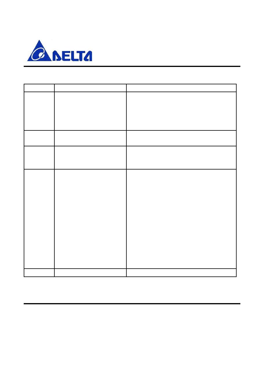
14 List of PSKEYS
PSKEY Function
Comments
3
Supported profiles
Bit 0 � Headset profile
Bit 1 � Serial port profile
Bit 2 � Dial-up networking profile
Bit 3 � Handsfree profile
Bit 4 � Fax profile
7
Hands Free Supported
Features
Described earlier
9
Time for host communication
wakeup
signal
In 1ms increments � Time for wake-up pulse to
ensure
host is ready to receive data
11
General Flags
Bit 0 � Default SCO Flag (0-HV3, 1 HV1)
Bit 1 � phone uses in-band ringing for headset
Bit 2 � Reserved
Bit 3 � Reserved
Bit 4 � Reserved
Bit 5 � Use 1.28s page scan interval
Bit 6 � Automatic SCO creation on ATA
Bit 7 � Automatic SCO disconnection on
AT+CHUP
Bit 8 - Automatic SCO creation on AT+BVRA=1
Bit 9 - Automatic SCO creation on
AT+CKPD=200
Bit 10 � Control SCO on call status events
14
Sniff mode parameters
Max interval, min interval, attempts, timeout
Preliminary
DLBM-CG121
Data Sheet
July 30, 2004
Proprietary Information and Specifications are Subject to Change
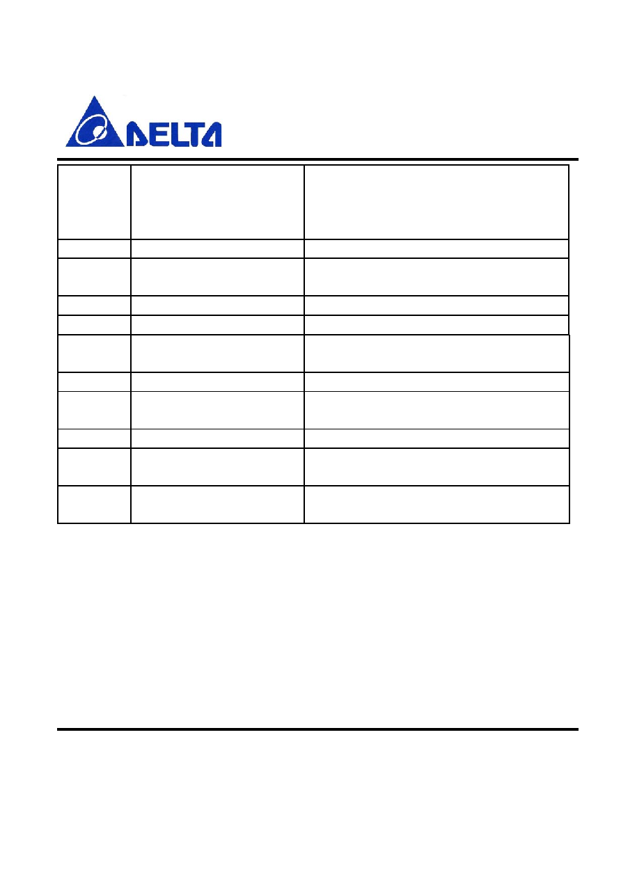
17
PIO configuration settings
Word 1 � Audio service indicator output
Word 2 � Disconnect service input
Word 3 � Data service indicator output
Word 4 � Host wakeup signal
30
Default AT String
Sent to phone when service disconnected
31
Headset Mode AT string
Sent to phone when connected to Headset
service
32
SPP Mode AT string
Sent to phone when connected to SPP service
33
DUN Mode AT string
Sent to phone when connected to DUN service
34
Hands Free Mode AT string
Sent to phone when connected to Hands Free
service
35
Fax Mode AT string
Sent to phone when connected to Fax service
36
Force Modem Disconnect AT
string
Sent to the phone when a DUN service is
disconnected
37
Alternative Call Answer string Used if present, otherwise ATA is used
38
Alternative Call disconnect
string
Used if present, otherwise AT+CHUP is used
39
Alternate Call Initiate string
Used to generate last number redial or voice tag
via AT commands.

Preliminary
DLBM-CG121
Data Sheet
July 30, 2004
Proprietary Information and Specifications are Subject to Change
15. RECOMMENDED REFLOW PROFILE
The temperature rise to 150 for preliminary heating shall be made for 30 seconds or longer.
The preliminary heating shall be done at the temperature of 160+10 for 60 ~ 90 seconds.
The heating shall be at the temperature of 200 or higher For 20 ~ 40 seconds and the peak
temperature shall be 230+5
Figure 7. REFLOW PROFILE
Preliminary
DLBM-CG121
Data Sheet
July 30, 2004
Proprietary Information and Specifications are Subject to Change
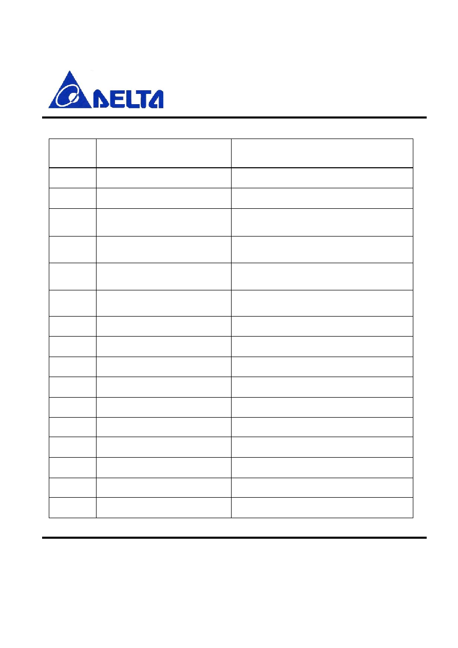
16.Pin description
Pin No.
Name
Description
1
PIO_11
Programmable I/O terminal
2
PIO_9
Programmable I/O terminal
3
PCM_OUT /Synchronous
data
output
4
PCM_SYNC /Synchronous
data
sync
5
PCM_CLK /Synchronous
data
clock
6
PCM_IN /Synchronous
data
input
7
Gnd
8
Gnd
9
Gnd
10
ANT RF
input/output
11
AIO_0 Programmable
input/output
12
Gnd
13
Gnd
14
Gnd
15
Vdd_1.8V
Refer to Power supply diagram
16
VREG_IN
Refer to Power supply diagram

Preliminary
DLBM-CG121
Data Sheet
July 30, 2004
Proprietary Information and Specifications are Subject to Change
17
VDD_IO
Refer to Power supply diagram
18
USB_DN
USB data minus
19
USB_DP
USB data plus with selectable internal 1.5k
ohm pull-up resistor
20
UART_TX
UART data output active high
21
UART_RX
UART data input active high
22
UART_CTS
UART clear to send active low
23
UART_RTS
UART request to send active low
24
Reset_B Reset
if
low
25
PIO_4
Programmable input/output line
26
PIO_5
Programmable input/output line
27
PIO_10
Programmable input/output line
28
PIO_3
Programmable input/output line
29
Gnd
30
Gnd
31
Gnd
32
PIO_2
Programmable input/output line
33
PIO_1
Programmable input/output line
34
PIO_0
Programmable input/output line
Preliminary
DLBM-CG121
Data Sheet
July 30, 2004
Proprietary Information and Specifications are Subject to Change
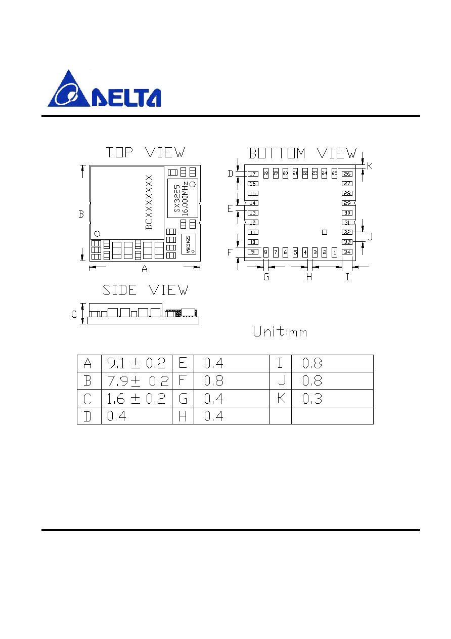
17.Dimensions (mm)
Figure 8. Output pin dimensions
Preliminary
DLBM-CG121
Data Sheet
July 30, 2004
Proprietary Information and Specifications are Subject to Change
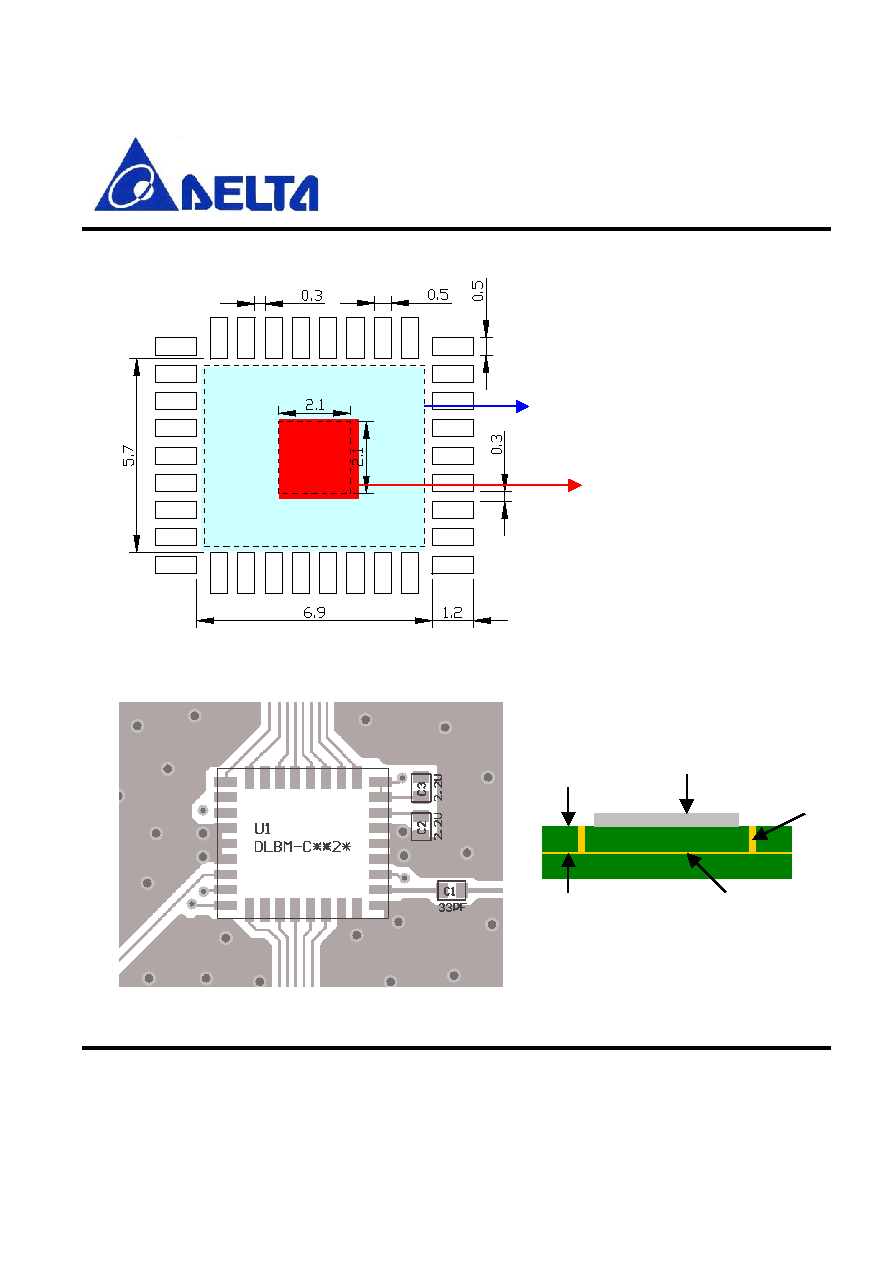
18. Layout Guide
U nit: m m
D on't place the ground on the top
layer (Inside area)
D o not place any copper foil
on the top layer (Inside area)
Figure 9. Land Pattern
Figure 10. Layout Example
Side V iew
D LBM -C**2*
G round V IA
M ain G round plant
T
5m il

Preliminary
DLBM-CG121
Data Sheet
July 30, 2004
Proprietary Information and Specifications are Subject to Change
Contact information
:
Website:
http://www.deltaww.com
Email:
Richard.meng@delta.com.tw
Tel No.: 886-3-3591968#2930