DV-704A Series
1X019DSD
11314 4th Avenue
West, Suite 206
Everett, WA 98204
http://www.vpt-inc.com
Sales Information:
Phone: (425) 353-3010
Fax: (425) 353-4030
E-mail: vptsales@vpt-inc.com
1
HIGH RELIABILITY HYBRID
EMI FILTERS
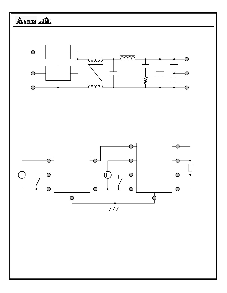
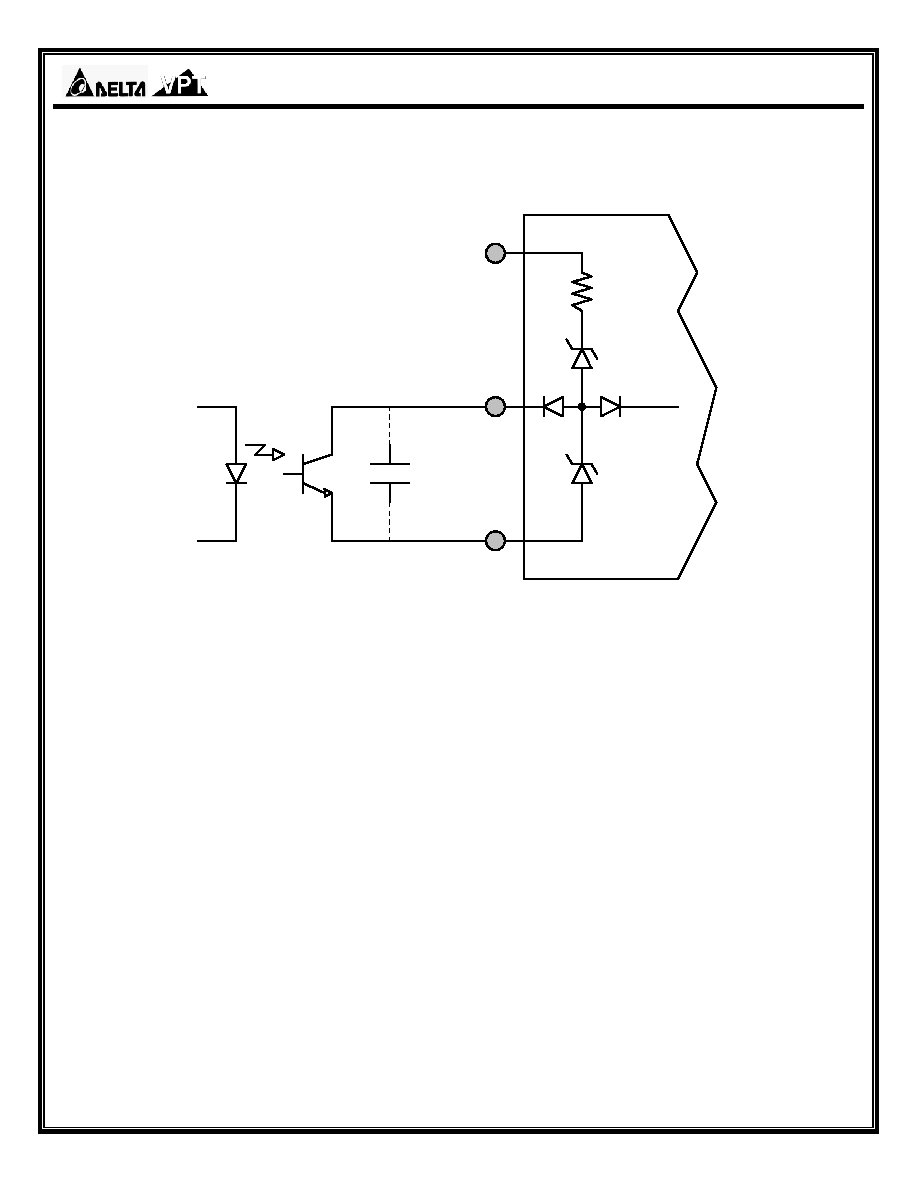
DESCRIPTION
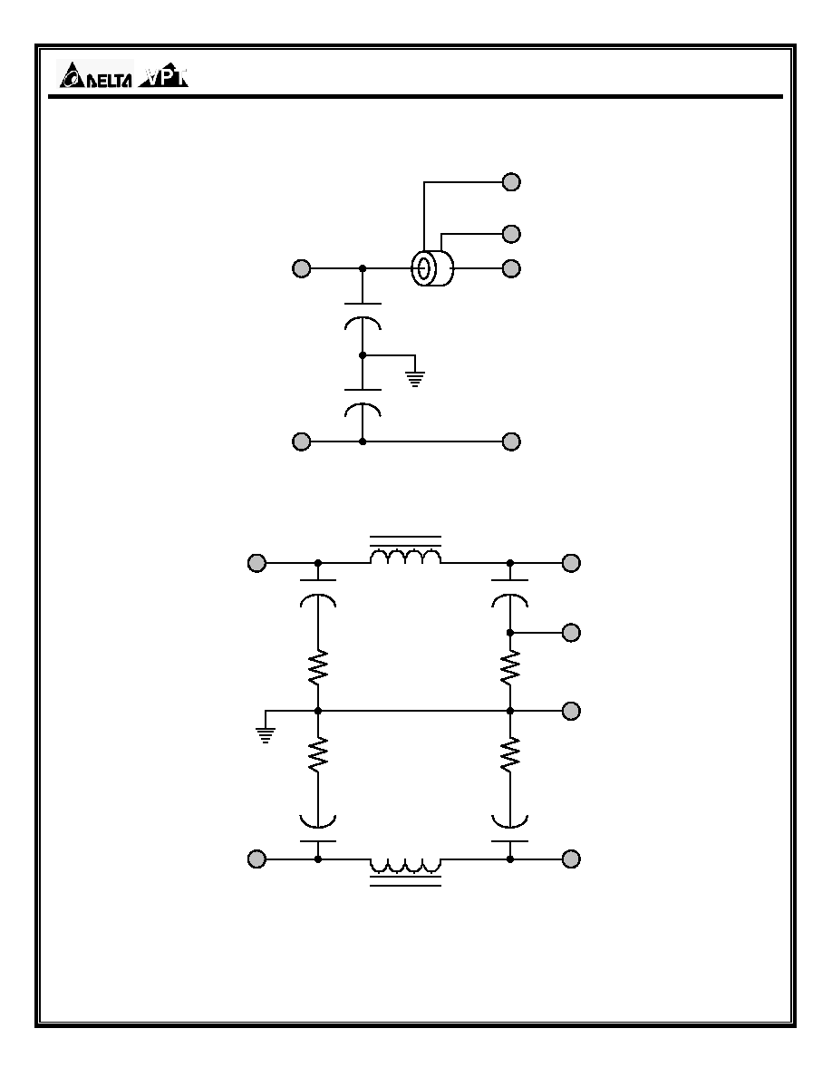
The DV-704A is a combined hybrid EMI filter and
voltage spike protection module that is operable over
the full military (-55 ∞C to +125 ∞C) temperature
range with no power derating. The DV-704A EMI
filter is designed to be used with VPT/Delta's DVSA,
DVHF, DVTR, and DVFL series DC-DC converters to
comply with the surge requirements of MIL-STD-
704A, B, C, and D with 40 watts maximum output
power. This device also reduces the reflected noise
of the DC-DC converters to meet MIL-STD-461C
CE03 and MIL-STD-461D CE102 limits. It also
protects the DC-DC converters against the voltage
spikes specified in MIL-STD-461C CS06 and
conducted susceptibility in MIL-STD-461C CS01 and
CS02.
These filters are designed and manufactured in a
facility qualified to ISO9001 and certified to MIL-
PRF-38534 and MIL-STD-883.
This product may incorporate one or more of the
following U.S. patents:
5,784,266
5,790,389
5,963,438
5,999,433
6,005,780
6,084,792
6,118,673
FEATURES
∑ High
Reliability
∑ Up to 2.0 Amps Maximum Current
∑ 40 dB Minimum Attenuation at 500 kHz
∑ Industry Standard Pinout
∑ Inrush Current Limit and Soft Start
∑ Under Voltage Lockout
∑ Clamps Output Voltage to 50 Volts Maximum
∑ Precision Seam Welded or Solder Seal
Hermetic Package
∑ Custom Versions Available
∑ Additional Environmental Screening Available
∑ Meets MIL-STD-704A, B, C, and D Surge Limits
∑ Compliant to MIL-STD-461C CE03 and MIL-
STD-461D CE102 EMC Requirements
∑ Protects Against Conducted Susceptibility
Specified in MIL-STD-461C, CS01 and CS02
and Against Voltage Spikes Specified in MIL-
STD-461C CS06
∑ MIL-PRF-38534 Element Evaluated
Components
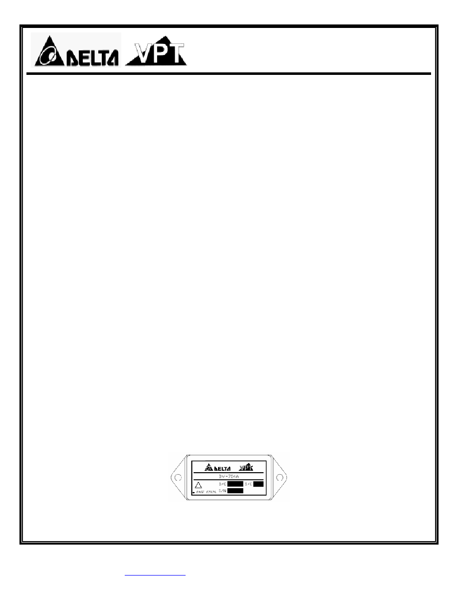
Figure 1
≠ DV-704A EMI Filter
(Not To Scale)

DV-704A Series
1X019DSD
2
SPECIFICATIONS
(T
CASE
= -55∞C to +125∞C, V
IN
= +28V ± 5%, Full Load, Unless Otherwise Specified)
ABSOLUTE MAXIMUM RATINGS
Input Voltage (Continuous)
40 V
DC
Power Dissipation (Continuous)
15 Watts
Input Voltage (Transient, up to 20
µs)
600 Volts
Power Dissipation (Peak)
500 Watts
Output Current
3
2.0 Amps
Storage Temperature
-65∞C to +150∞C
Weight (Maximum)
47 grams
Lead Solder Temperature (10 seconds)
300∞C
DV-704A
Parameter Conditions
Min Typ
Max
Units
STATIC
Continuous No
Load
0
28
40
V
Continuous 2.0 A Load
15
28
40
V
Transient 100 ms, R
S
= 0.0 -
-
80
V
Transient 60 ms, R
S
= 0.5 -
-
100
V
INPUT
Voltage
2
Transient 20
µs, R
S
= 50
- -
600
V
No Load
-
-
10
mA
Current
1
Inhibited -
-
2.0
mA
OUTPUT
Voltage
Continuous V
OUT
= V
IN
≠ (I
IN
x R
DC
) V
Current
3,4
Continuous 0
-
2.0
A
Open Circuit
-
14
16
V
INHIBIT PIN VOLTAGE
2
Inhibited 0
-
0.8
V
INHIBIT PIN CURRENT
2
Inhibit Pin Voltage = 0 to 0.8 V
-
-
-300
µA
UNDERVOLTAGE LOCKOUT
7.0
-
14
V
OUTPUT CLAMP VOLTAGE
43
-
47
V
2.0 A Load, 80 V
-
-
100
ms
INPUT SURGE LIMIT
2
2.0 A Load, 100 V
-
-
80
ms
2.0 A Load, 600 V, R
S
= 50 -
-
20
µs
INPUT SPIKE LIMIT
2
2.0 A Load, 400 V, R
S
= 0.5 -
-
20
µs
INPUT INRUSH CURRENT
2
V
IN
= 0 ≠ 28V, No Load
C
L
= 100
µF
- 0.25
0.5
A
PK
DC RESISTANCE
Continuous
-
-
450
m
Continuous -
-
15
W
POWER DISSIPATION
Peak -
-
500
W
NOISE REJECTION
f = 500 kHz
50
-
-
dB
CAPACITANCE
2
Pin to Case
-
20
-
nF
ISOLATION
Any Pin to Case, 500 V
DC
100 - -
M
MTBF (MIL-HDBK-217F)
AIF @ T
C
= 55∞C
-
0.627
-
MHrs
Notes: 1. Derate linearly to 0 at 135∞C.
2. Verified by qualification testing.
3. Maximum output power is linearly derated to 0 A from +125∞C to +135∞C.
4. Rated current applies at any voltage.