6-36
Dialight Corporation ∑ 1501 Route 34 South ∑ Farmingdale, NJ 07727 ∑ TEL: (732) 919-3119 ∑ FAX: (732) 751-5778 ∑www.dialight.com
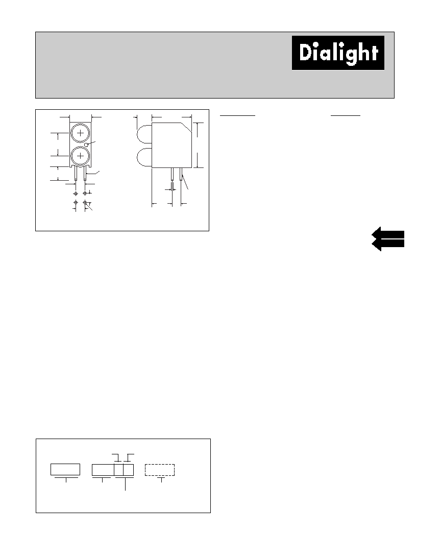
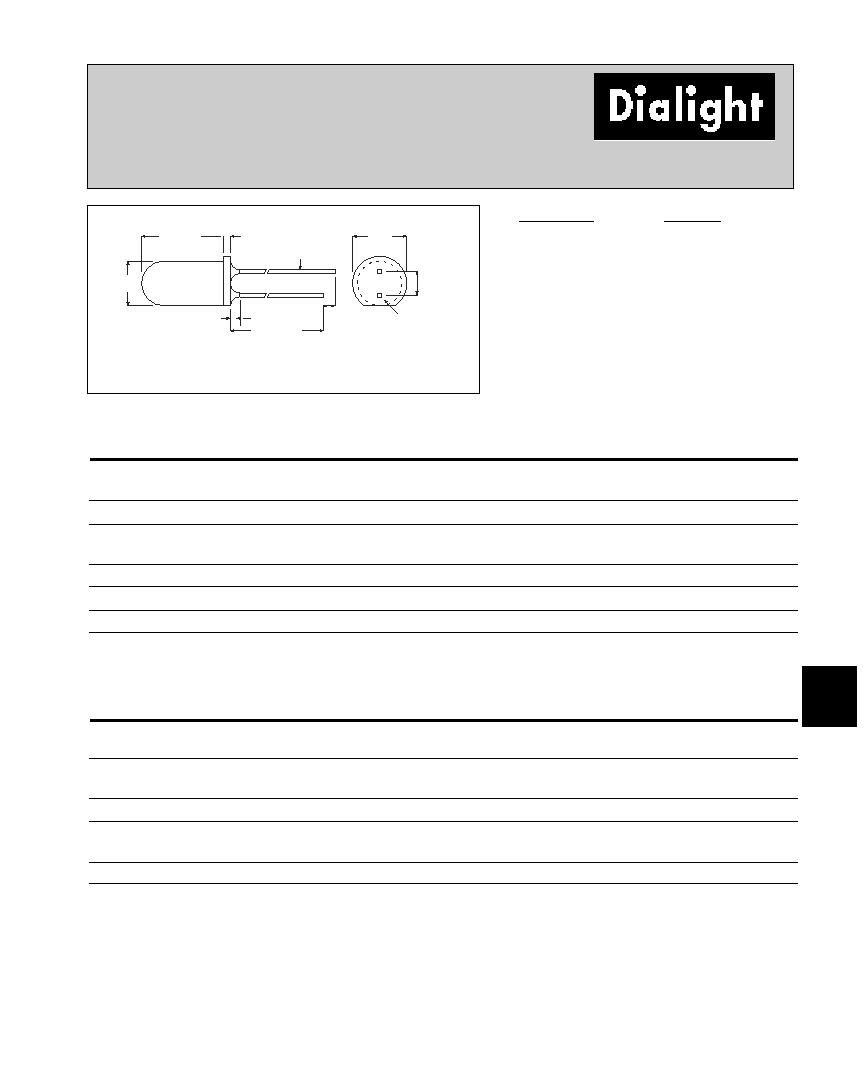
5mm
LED CBI
Æ
Circuit Board Indicator
Bi-level
552-0xxx
RECOMMENDED
P.C. BOARD
LAYOUT
CATHODE
Red Cathode for
Red/Green Bi-Color
Yellow Cathode for
Yellow/Green Bi-Color
6.0 [.235]
6.35
[.250]
3.2
[.125]
2.54 [.100]
5.6
[.220]
10.9 [.430]
4.45
[.175]
3.68
[.145]
2.54
[.100]
Top LED
CATHODE
I.D.
2.54 [.100]
2.54
[.100]
1.1
[.043]
.508
[.020]
12.52
[.493]
PART NO.
COLOR*
HIGH EFFICIENCY, LED TYPE 02
552-0211
Red
552-0222
Green
552-0233
Yellow
552-0277
Orange
INTEGRAL RESISTOR 5 VOLTS, LED TYPE 03
552-0311
Red
552-0322
Green
552-0333
Yellow
INTEGRAL RESISTOR 12 VOLTS, LED TYPE 04
552-0422
Green
552-0433
Yellow
BI-COLOR, LED TYPE 07
552-0711
Red/Green
552-0744
Yellow/Green
SUPER BRIGHT, LED TYPE 08
552-0811
Red
552-0822
Green
552-0833
Yellow
LOW CURRENT, LED TYPE 09
552-0911
Red
552-0922
Green
552-0933
Yellow
Features
∑ Multiple CBIs form horizontal LED arrays on 6.35mm
(0.250") center-lines.
∑ High Contrast, UL 94 V-0 rated, black housing
∑ Oxygen index: 32%
∑ Polymer content: PBT, 0.710 g
∑ Housing stand-offs facilitate PCB cleaning
∑ Solderability per MIL-STD-202F, method 208F
∑ LEDs are safe for direct viewing per IEC 825-1,
EN-60825-1
Custom Combinations
∑ Contact factory for information on custom color
combinations and ganged arrays
Tolerance note: As noted, otherwise:
∑ LED Protrusion: ±0.04 mm [±0.016]
∑ CBI Housing: ±0.02mm[±0.008]
Dimensions in mm [inches]
Standard Polarity shown in drawing: Cathode right
To order any of the 552-0xxx part numbers with
Reverse Polarity (Cathode Left), please add -010 to
the part numbers shown above.
NEW
5 5 2
0 x x x
0 1 0
Reverse Polarity Option
1) Cathode Left
≠010 Ordering Code Suffix required ONLY for Reverse Polarity Option
LED Type
Color
Top Position
Bottom Position
PART NUMBER ORDERING CODE
Series
0) Blank 1) Red or Red/Green Bi-Color 2) Green 3) Yellow
4) Yellow/Green Bi-Color 7) Orange
≠
≠
NEW
6-37
Dialight Corporation ∑ 1501 Route 34 South ∑ Farmingdale, NJ 07727 ∑ TEL: (732) 919-3119 ∑ FAX: (732) 751-5778 ∑www.dialight.com
6
Peak
I
V
Test
Forward
Viewing
LED
Part Number
Color
Wavelength nm
mcd
Voltage
Current (mA)
Angle 2
Ω
Data sheet
Page #
552-0311
Red
655
2
5
13
60∞
5RD-9422
6-52
552-0322
Green
565
8
5
12
60∞
5RD-9423
6-52
552-0333
Yellow
583
8
5
10
60∞
521-9284
6-41
552-0xxx
Peak
I
V
V
F
Test
Viewing
LED
Part Number
Color
Wavelength nm
mcd
Volts
Current (mA)
Angle 2
Ω
Data sheet
Page #
552-0211
Red
650
7
2.2
10
50∞
5HD-9269
6-49
552-0222
Green
563
10
2.1
10
65∞
5HD-9270-5
6-49
552-0233
Yellow
585
6.3
2.1
10
50∞
5HD-9271-5
6-49
552-0277
Orange
600
7
1.9
10
60∞
521-9704
6-43
HIGH EFFICIENCY
See page 6-55 and 6-56 for Reference Only LED Drive Circuit Examples. See page 6-58 for Pin Out
Peak
I
V
V
F
Test
Viewing
LED
Part Number
Color
Wavelength nm
mcd
Volts
Current (mA)
Angle 2
Ω
Data sheet
Page #
552-0911
Red
635
2
1.8
2
50∞
521-9320
6-42
552-0922
Green
565
1.8
1.8
2
50∞
521-9327
6-42
552-0933
Yellow
583
1.8
1.9
2
50∞
521-9321
6-42
LOW CURRENT
Peak
I
V
V
F
Test
Viewing
LED
Part Number
Color
Wavelength nm
mcd
Volts
Current (mA)
Angle 2
Ω
Data sheet
Page #
552-0811
Red
650
34
2.1
20
50∞
5SD-9441
6-53
552-0822
Green
563
34
2.2
20
50∞
5SD-9456
6-53
552-0833
Yellow
585
34
2.2
20
50∞
5SD-9455
6-53
SUPER BRIGHT
Peak
I
V
V
F
Test
Viewing
LED
Part Number
Color
Wavelength nm
mcd
Volts
Current (mA)
Angle 2
Ω
Data sheet
Page #
552-0711
Red/Green
660/565
90/40
1.8/2.1
20
60∞
521-9651
6-46
552-0744
Yellow/Green
585/565
8.7/8.7
2.1/2.1
20
50∞
521-9724
6-46
BI-COLOR
INTEGRAL RESISTOR, 5 VOLTS
Typical Operating Characteristics (T
A
=25∞C)
See LED data sheet for additional information
Peak
I
V
Test
Forward
Viewing
LED
Part Number
Color
Wavelength nm
mcd
Voltage
Current (mA)
Angle 2
Ω
Data sheet
Page #
552-0422
Green
565
4
12
13
60∞
5RD-9378
6-52
552-0433
Yellow
583
4
12
13
60∞
5RD-9379
6-52
INTEGRAL RESISTOR, 12 VOLTS
Red
Yellow
ABSOLUTE MAXIMUM RATINGS
(T
A
=25∞C)
-9183
-9284
Forward Voltage (V)
7.5
7.5
Derating (V/∞C) From 50∞C
.071
.071
Operating Temperature (∞C)
-40/+85
-40/+85
Storage Temperature (∞C)
-55/+100
-55/+100
Soldering Temperature
260∞C, 5 seconds, 1.6 mm from case
6-41
Dialight Corporation ∑ 1501 Route 34 South ∑ Farmingdale, NJ 07727 ∑ TEL: (732) 919-3119 ∑ FAX: (732) 751-5778 ∑www.dialight.com
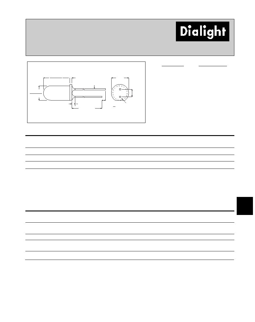
6
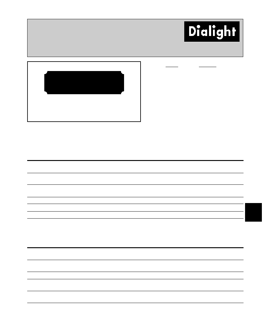
5mm Discrete LED
Integral Resistor, 5 Volts
Diffused
9.19 [.362]
8.43 [.332]
.76
[.030]
25.1 [1.00]
MIN
1.27
[.050]
.64
[.025]
5.84
[.230]
2.54
[.100]
CATHODE
1.0
[.040]
MAX
1.0
[.040]
MAX
5.08 [.200]
4.57 [.180]
PART NO.
LED COLOR
521-9183
Red
521-9284
Yellow
Dimensions in mm [inches]
MOUNTING CLIP: 515-0004
located on page 6-48
Red
Yellow
OPERATING CHARACTERISTICS
(T
A
=25∞C)
-9183
-9284
Luminous Intensity (mcd)
Min.
2
2
VF = 5V
Typical
8
8
Peak Wavelength (nm)
Typical
635
583
Peak
Viewing Angle (2
Ω
)
Typical
60∞
60∞
Forward Current (I)
Typical
10
10
VF = 5V
Max
15
15
Reverse Voltage (V), IR=100µA
Min.
5
5
is the off axis angle at which the luminous intensity is half the axial luminous intensity
Solder Adherence per MIL-STD-202E, Method 208C
521-9183, -9284
6-42
Dialight Corporation ∑ 1501 Route 34 South ∑ Farmingdale, NJ 07727 ∑ TEL: (732) 919-3119 ∑ FAX: (732) 751-5778 ∑www.dialight.com
Red
Yellow
Green
ABSOLUTE MAXIMUM RATINGS
(TA=25∞C)
-9320
-9321
-9327
Power Dssipation (mW)
27
36
24
Derating (mA/∞C)
From 92∞C
1
1
1
Forward Current (mA)
7
7
7
Peak Current (mA)
500
500
500
Pulse width = 10 µs
Operating Temperature (∞C)
-55/+100
-55/+100
-55/+100
Storage Temperature (∞C)
-55/+100
-55/+100
-55/+100
Soldering Temperature
260∞C, 5 seconds, 1.6 mm from case
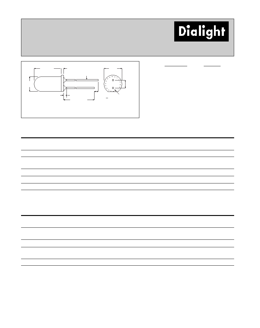
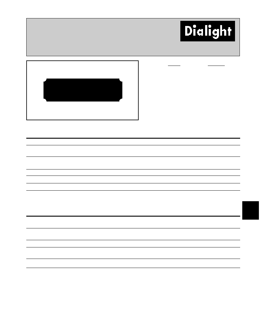
5mm Discrete LED
Low Current, 2mA
Diffused
521-9320, -9321, -9327
8.81 [.347]
.76
[.030]
25.1 [1.00]
MIN
1.27
[.050]
4.83
[.190]
.46
[.018]
5.84
[.230]
2.54
[.100]
CATHODE
1.0
[.040]
MAX
1.0
[.040]
MAX
PART NO.
COLOR
521-9320
Red
521-9321
Yellow
521-9327
Green
Red
Yellow
Green
OPERATING CHARACTERISTICS
(TA=25∞C)
-9320
-9321
-9327
Luminous Intensity (mcd)
Min.
1.2
1.2
1.2
IF=2mA
Typical
2
1.8
1.8
Peak Wavelength (nm)
Typical
635
583
565
Peak
Viewing Angle (2
Ω
)
Typical
50∞
50∞
50∞
Forward Voltage (V)
Typical
1.8
1.9
1.8
IF=2mA
Max.
2.2
2.7
2.2
Reverse Voltage (V), IR=50µA
Min.
5
5
5
Dimensions in mm [inches]
MOUNTING CLIP: 515-0004
located on page 6-48
is the off axis angle at which the luminous intensity is half the axial luminous intensity
Solder Adherence per MIL-STD-202E, Method 208C
6-43
Dialight Corporation ∑ 1501 Route 34 South ∑ Farmingdale, NJ 07727 ∑ TEL: (732) 919-3119 ∑ FAX: (732) 751-5778 ∑www.dialight.com
6
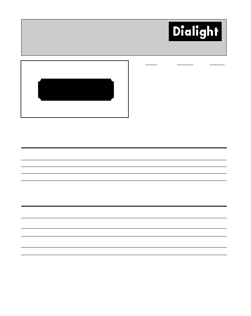
5mm Discrete LED
High Efficiency
Diffused
521-9246, -9248, -9250, -9704
8.81 [.347]
.76
[.030]
25.1 [1.00]
MIN
1.27
[.050]
4.83
[.190]
.46
[.018]
5.84
[.230]
2.54
[.100]
CATHODE
1.0
[.040]
MAX
PART NO.
COLOR
521-9246
Red
521-9248
Yellow
521-9250
Green
521-9704
Orange
Red
Yellow
Green
Orange
ABSOLUTE MAXIMUM RATINGS
(T
A
=25∞C)
-9246
-9248
-9250
-9704
Power Dissipation (mW)
135
85
135
135
Derating (mW/∞C)
From 25∞C 1. (mA/∞C) From 50∞C
1.8
1.6
1.8
.5
1
Forward Current (mA)
25
20
25
30
Peak Current (mA)
500
500
500
500
Pulse width = 10µs
Operating Temperature (∞C)
-55/+100
-55/+100
-20/+100
-55/+100
Storage Temperature (∞C)
-55/+100
-55/+100
-55/+100
-55/+100
Soldering Temperature
260∞C, 5 seconds, 1.6 mm from case
Red
Yellow
Green
Orange
OPERATING CHARACTERISTICS
(T
A
=25∞C)
-9246
-9248
-9250
-9704
Luminous Intensity (mcd)
Min.
4
4
4.2
4
IF=10mA
Typical
7
8
5.2
7
Peak Wavelength (nm)
Typical
635
583
565
600
Peak
Viewing Angle (2
Ω
)
Typical
60∞
60∞
60∞
60∞
Forward Voltage (V)
Typical
2.2
2.2
2.3
1.9
IF=10mA
Max.
3
3
3
2.4
Reverse Voltage (V), IR=100µA
Min.
5
5
5
5
Dimensions in mm [inches]
MOUNTING CLIP: 515-0004
located on page 6-48
Solder Adherence per MIL-STD-202E, Method 208C
is the off axis angle at which the luminous intensity is half the axial luminous intensity

6-46
Dialight Corporation ∑ 1501 Route 34 South ∑ Farmingdale, NJ 07727 ∑ TEL: (732) 919-3119 ∑ FAX: (732) 751-5778 ∑www.dialight.com
5mm Discrete LED
Bi-Color
Non-Tinted, Diffused
521-9651, -9724
5.00
[.197]
8.64[.340]
22.1 [.87]
MIN.
0.51
[.020]
CATHODE
GREEN,
RED/GREEN
BI-COLOR
521-9651
CATHODE
YELLOW,
YELLOW/GREEN
BI-COLOR
521-9724
1.00
[.04]
5.59
[.220]
2.54
[.100]
1.50
[.059]
MAX
PART NO.
LED COLOR
521-9651
Red/Green
521-9724
Yellow/Green
Red/Green
Yellow/Green
ABSOLUTE MAXIMUM RATINGS
(T
A
=25∞C)
-
9651
-9724
Power Dissipation (mW)
100/100
60/100
Forward Current (mA)
40/30
20/30
Derating (mA/∞C)
From 50∞C
.5/.4
.25/.40
Peak Current (mA)
200/120
80/120
Pulse width = 100 µs
Operating Temperature (∞C)
-55/+100
-55/+100
Storage Temperature (∞C)
-55/+100
-55/+100
Soldering Temperature
260∞C, 5 seconds, 1.6 mm from case
Red/Green
Yellow/Green
OPERATING CHARACTERISTICS
(T
A
=25∞C)
-9651
-9724
Luminous Intensity (mcd)
Min.
29/12.6
2.5/2.5
IF=20mA
Typical
90/40
8.7/8.7
Peak Wavelength (nm)
Typical
660/565
585/565
Peak
Viewing Angle (2
Ω
)
Typical
60∞
50∞
Forward Voltage (V)
Typical
1.8/2.1
2.1/2.1
IF=20mA
Max.
2.4/2.8
2.8/2.8
Dimensions in mm [inches]
MOUNTING CLIP: 515-0005
located on page 6-48
is the off axis angle at which the luminous intensity is half the axial luminous intensity
Solder Adherence per MIL-STD-202E, Method 208C

6-47
Dialight Corporation ∑ 1501 Route 34 South ∑ Farmingdale, NJ 07727 ∑ TEL: (732) 919-3119 ∑ FAX: (732) 751-5778 ∑www.dialight.com
6
5mm Discrete LED
Super Bright, Water Clear
Non-Tinted, Non-Diffused
521-9464,-9465,-9466
8.81 [.347]
4.83
[.190]
25.35 [.998]
MIN
1.27
[.050]
TYP
2.54
[.100]
.46
[.018] SQ.
CATHODE
5.84
[.230]
1.0
[.040]
MAX
PART NO.
COLOR
521-9464
Red
521-9465
Green
521-9466
Yellow
Red
Green
Yellow
ABSOLUTE MAXIMUM RATINGS
(T
A
=25∞C)
-9464
-9465
-9466
Power Dissipation (mW)
135
135
85
Derating (mW/∞C)
From 25∞C 1. From 50 ∞C
1.8
1.8
1.6
1
Forward Current (mA)
30
30
20
Peak Current (mA)
500
500
500
Pulse width = 10 µs
Operating Temperature (∞C)
-55/+100
-20/+100
-55/+100
Storage Temperature (∞C)
-55/+100
-55/+100
-55/+100
Soldering Temperature
260 ∞C, 5 seconds, 1.6 mm from case
Red
Green
Yellow
OPERATING CHARACTERISTICS
(T
A
=25∞C)
-9464
-9465
-9466
Luminous Intensity (mcd)
Min.
80
80
80
IF=20mA
Typical
125
120
140
Peak Wavelength (nm)
Typical
635
565
583
Peak
Viewing Angle (2
Ω
)
Typical
24∞
24∞
24∞
Forward Voltage (V)
Typical
2.2
2.3
2.2
IF=20mA
Max.
3
3
3
Reverse Voltage (V), IR=100µA
Min.
5
5
5
Dimensions in mm [inches]
MOUNTING CLIP: 515-0004
located on page 6-48
is the off axis angle at which the luminous intensity is half the axial luminous intensity
Solder Adherence per MIL-STD-202E, Method 208C
6-49
Dialight Corporation ∑ 1501 Route 34 South ∑ Farmingdale, NJ 07727 ∑ TEL: (732) 919-3119 ∑ FAX: (732) 751-5778 ∑www.dialight.com
6
OPERATING CHARACTERISTICS
Red
Green
Green
Yellow
Yellow
(T
A
=25∞C)
-9269
-9270-2
-9270-5
-9271-2
-9271-5
Luminous Intensity (mcd)
Min.
2.2
4
3.6
4
2.2
IF=10mA
Typical
7
32
10
10
6.3
Peak Wavelength (nm)
Typical
650
565
563
590
585
Peak
Viewing Angle (2
Ω
)
Typical
50∞
50∞
65∞
70∞
50∞
Forward Voltage (V)
Typical
2.2
2*
2.1
2.4*
2.1
IF=10mA, *IF=20mA
Max.
2.5
2.6*
3
3*
3
Reverse Voltage (V),
Min.
5
5*
3*
5*
3
IR=100µA *IR=10µA
ABSOLUTE MAXIMUM RATINGS
Red
Green
Green
Yellow
Yellow
(T
A
=25∞C)
-9269
-9270-2
-9270-5
-9271-2
-9271-5
Power Dissipation (mW)
60
140
75
200
60
Derating (mW/∞C)
From 50∞C 1. From 40∞C
.66
1
.66
1
.66
1
Forward Current (mA)
20
40
25
60
20
Derating (mA/∞C)
From 25∞C
.6
.8
Peak Current (mA)
60
500
60
1000
60
Pulse width = 1µs
Operating Temperature (∞C)
-25/+85
-55/+100
-25/+85
-55/+100
-25/+85
Storage Temperature (∞C)
-30/+100
-55/+100
-30/+100
-55/+100
-30/+100
Soldering Temperature
260∞C, 5 seconds, 1.6 mm from case
5mm
High Efficiency
Diffused
5HD-xxxx
TYPE
COLOR
*5HD-9269
Red
*5HD-9270-2
Green
*5HD-9270-5
Green
*5HD-9271-2
Yellow
*5HD-9271-5
Yellow
* NOT A VALID PART
NUMBER. THIS SHEET IS FOR
REFERENCE ONLY.
is the off axis angle at which the luminous intensity is half the axial luminous intensity
Solder Adherence per MIL-STD-202E, Method 208C
6-51
Dialight Corporation ∑ 1501 Route 34 South ∑ Farmingdale, NJ 07727 ∑ TEL: (732) 919-3119 ∑ FAX: (732) 751-5778 ∑www.dialight.com
6
5mm
General Purpose
Diffused
5ND-xxxx
TYPE
COLOR
*5ND-9672
Red
*5ND-9673
Yellow
*5ND-9674
Green
Red
Yellow
Green
ABSOLUTE MAXIMUM RATINGS
(T
A
=25∞C)
-9672
-9673
-9674
Power Dissipation (mW)
80
60
100
Forward Current (mA)
40
20
30
Derating (mA/∞C)
From 25∞C
.5
.25
.4
Peak Current (mA)
200
80
120
Pulse width = 10 µs
Operating Temperature (∞C)
-55/+100
-55/+100
-55/+100
Storage Temperature (∞C)
-55/+100
-55/+100
-55/+100
Soldering Temperature
260∞C, 5 seconds, 1.6 mm from case
Red
Yellow
Green
OPERATING CHARACTERISTICS
(T
A
=25∞C)
-9672
-9673
-9674
Luminous Intensity (mcd)
Min.
3.5
3.5
3.5
IF=20mA
Typical
12.3
12.3
12.3
Peak Wavelength (nm)
Typical
635
585
565
Peak
Viewing Angle (2
Ω
)
Typical
60∞
60∞
60∞
Forward Voltage (V)
Typical
2
2.1
2.1
IF=20mA
Max.
2.8
2.8
2.8
Reverse Voltage (V), IR=100µA
Min.
5
5
5
* NOT A VALID PART
NUMBER. THIS SHEET IS FOR
REFERENCE ONLY.
is the off axis angle at which the luminous intensity is half the axial luminous intensity
Solder Adherence per MIL-STD-202E, Method 208C
6-52
Dialight Corporation ∑ 1501 Route 34 South ∑ Farmingdale, NJ 07727 ∑ TEL: (732) 919-3119 ∑ FAX: (732) 751-5778 ∑www.dialight.com
ABSOLUTE MAXIMUM RATINGS
Green 12V
Yellow 12V
Red 5V
Green 5V
(T
A
=25∞C)
-9378
-9379
-9422
-9423
Forward Voltage (V)
1 5 *
1 5
7.5
7.5
*(T
A
=70∞C)
Operating Temperature (∞C)
-20/+85
-40/+85
-40/+85
-20/+85
Storage Temperature (∞C)
-55/+100
-55/+100
-55/+100
-55/+100
Soldering Temperature
260∞C, 5 seconds, 1.6 mm from case
OPERATING CHARACTERISTICS
Green 12V
Yellow 12V
Red 5V
Green 5V
(T
A
=25∞C)
-9378
-9379
-9422
-9423
Luminous Intensity (mcd)
Min.
1.5*
1.5*
1
2
VF=5V, *VF=12V Typical
4*
4*
2
8
Peak Wavelength (nm)
Typical
565
583
655
565
Peak
Viewing Angle (2
Ω
)
Typical
60∞
60∞
60∞
60∞
Forward Current (mA), VF=5V
Typical
13*
13*
13
12
*VF=12V
Max.
20*
20*
20
15
Reverse Voltage (V), IR=100µA
Typical
5
5
5
5
5mm
Integral Resistor
Diffused
5RD-xxxx
TYPE
COLOR
VOLTS
*5RD-9378
Green
12
*5RD-9379
Yellow
12
*5RD-9422
Red
5
*5RD-9423
Green
5
* NOT A VALID PART
NUMBER. THIS SHEET IS FOR
REFERENCE ONLY.
is the off axis angle at which the luminous intensity is half the axial luminous intensity
Solder Adherence per MIL-STD-202E, Method 208C
6-53
Dialight Corporation ∑ 1501 Route 34 South ∑ Farmingdale, NJ 07727 ∑ TEL: (732) 919-3119 ∑ FAX: (732) 751-5778 ∑www.dialight.com
6
5mm
Super Bright LED
Diffused
5SD-xxxx
TYPE
COLOR
*5SD-9441
Red
*5SD-9455
Yellow
*5SD-9456
Green
Red
Yellow
Green
ABSOLUTE MAXIMUM RATINGS
(T
A
=25∞C)
-9441
-9455
-9456
Power Dissipation (mW)
75
75
75
Forward Current (mA)
25
25
25
Derating (mA/∞C)
From 50∞C *
(mW/∞C)
From 40∞C
.66*
.5
.5
Peak Current (mA)
60
60
60
Pulse width = 1 ms
Operating Temperature (∞C)
-55/+100
-55/+100
-55/+100
Storage Temperature (∞C)
-55/+100
-55/+100
-55/+100
Soldering Temperature
260∞C, 5 seconds, 1.6 mm from case
Red
Yellow
Green
OPERATING CHARACTERISTICS
(T
A
=25∞C)
-9441
-9455
-9456
Luminous Intensity (mcd)
Min.
17
17
17
IF=20mA
Typical
34
34
34
Peak Wavelength (nm)
Typical
650
585
563
Peak
Viewing Angle (2
Ω
)
Typical
50∞
50∞
50∞
Forward Voltage (V)
Typical
2.1
2.2
2.2
IF=20mA
Max.
2.55
3
3
Reverse Voltage (V), IR=10µA
Min.
3
3
3
* NOT A VALID PART
NUMBER. THIS SHEET IS FOR
REFERENCE ONLY.
is the off axis angle at which the luminous intensity is half the axial luminous intensity
Solder Adherence per MIL-STD-202E, Method 208C