
5-7
Dialight Corporation ∑ 1501 Route 34 South ∑ Farmingdale, NJ 07727 ∑ TEL: (732) 919-3119 ∑ FAX: (732) 751-5778 ∑www.dialight.com
5
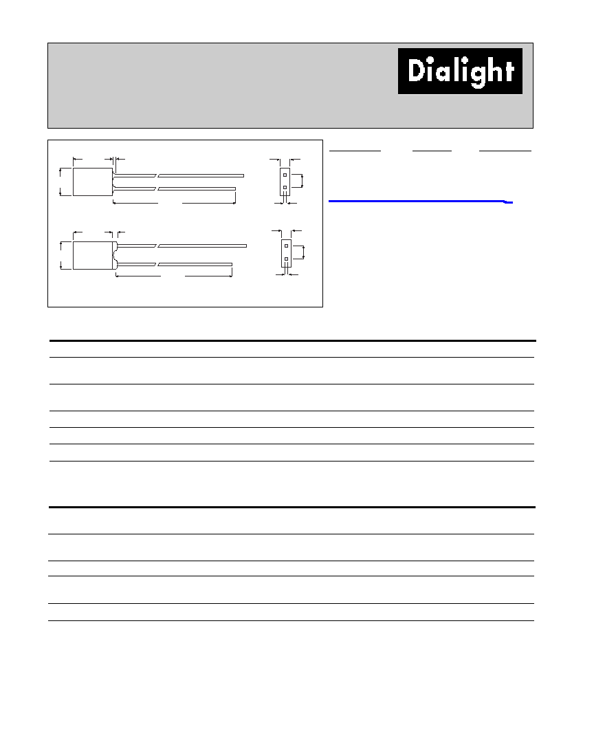
2mm x 5mm Rectangular
LED CBI
Æ
Circuit Board Indicator
566-xx06
3.81
[.150]
11.68 [.46]
5.05
[.199]
3.43
[.135]
7.62
[.300]
10.16
[.400]
2X .50
[.020]
SQ.
2.79
[.110]
3.81
[.150]
6.35
[.250]
ÿ 1.24
[.049]
2X ÿ 1.01
[.040]
RECOMMENDED
HOLE PATTERN GUIDE
3.81
[.150]
.50
[.020]
.51
[.020]
7.11
[.280]
1.91
[.075]
D
2.11
[.083]
1.27
[.050]
ÿ 1.02
[.040]
ANODE
3.68
[.145]
Cathode
PART NO.
COLOR
566-0206
Green
566-0306
Yellow
566-0406
Red
Features
∑ Multiple CBIs form horizontal LED arrays on 3.96mm
(0.156") center-lines
∑ High Contrast, UL 94 V-0 rated, black housing
∑ Oxygen index: 32%
∑ Polymer content: PBT, 0.309 g
∑ Housing stand-offs facilitate PCB cleaning
∑ Solderability per MIL-STD-202F, method 208F
∑ LEDs are safe for direct viewing per IEC 825-1,
EN-60825-1
Dimensions in mm [inches]
Tolerance note: As noted, otherwise:
∑ LED Protrusion: ±0.04 mm [±0.016]
∑ CBI Housing: ±0.02mm[±0.008]
Peak
I
V
V
F
Test
Viewing
LED
Part Number
Color
Wavelength nm
mcd
Volts
Current (mA)
Angle 2
Ω
Data sheet
Page #
566-0206
Green
565
4
2.2
20
110∞
521-9332
5-16
566-0306
Yellow
583
3.5
2.1
20
110∞
521-9452
5-16
566-0406
Red
635
7.4
2
20
140∞
521-9499
5-16
Typical Operating Characteristics (T
A
=25∞C)
See LED data sheet for additional information
See Page 5-20 and 5-21 for Reference Only LED Drive Circuit Example
See Page 5-22 for Pin Out
5-16
Dialight Corporation ∑ 1501 Route 34 South ∑ Farmingdale, NJ 07727 ∑ TEL: (732) 919-3119 ∑ FAX: (732) 751-5778 ∑www.dialight.com
2mm x 5mm Discrete LED
Rectangular
Tinted, Diffused
521-9332, -9452, -9499, -9718
4.82
[.190]
7.70 [.303]
25.4 [1.00]
.51
[.020]
2.54
[.100]
2.11
[.083]
DRAWING A
25.4 [1.00]
5.00
[.197]
DIM.
L
1.00
[.040]
DRAWING B
.51
[.020]
2.54
[.100]
2.00
[.079]
CATHODE
CATHODE
DIM. L
Red 7.50 [.295]
Blue 7.00 [.275]
1.00
[.040]
Green
Yellow
Red
Blue
ABSOLUTE MAXIMUM RATINGS
(T
A
=25∞C)
-9332
-9452
-9499
-9718
Power Dissipation (mW)
135
85
100
189
Forward Current (mA)
30
20
30
30
Derating (mA/∞C)
From 50∞C 1. mW/∞C From 25∞C
.5
.34
.4
.45
1
Peak Current (mA)
500*
500*
120
180
Pulse width = 1 ms *Pulse width = 10
µ
s
Operating Temperature (∞C)
-20/+100
-55/+100
-55/+100
-25/+75
Storage Temperature (∞C)
-55/+100
-55/+100
-55/+100
-25/+100
Soldering Temperature
260∞C, 5 seconds, 1.6 mm from case
Green
Yellow
Red
Blue
OPERATING CHARACTERISTICS
(T
A
=25∞C)
-9332
-9452
-9499
-9718
Luminous Intensity (mcd)
Min.
2.6
2.2
3
9
IF=20mA
Typical
4
3.5
7.4
18
Peak Wavelength (nm)
Typical
565
583
635
430
Peak
Viewing Angle (2
Ω
)
Typical
110∞
110∞
140∞
120∞
Forward Voltage (V)
Typical
2.2
2.1
2
5.3
IF=20mA
Max.
3
2.6
2.8
6
Reverse Voltage (V), IR=100µA
Min.
5
5
5
5
Dimensions in mm [inches]
PART NO.
COLOR
DRAWING
521-9332
Green
A
521-9452
Yellow
A
521-9499
Red
B
521-9718
Blue
B
is the off axis angle at which the luminous intensity is half the axial luminous intensity
Solder Adherence per MIL-STD-202E, Method 208C