5-11
Dialight Corporation ∑ 1501 Route 34 South ∑ Farmingdale, NJ 07727 ∑ TEL: (732) 919-3119 ∑ FAX: (732) 751-5778 ∑www.dialight.com
5
Peak
I
V
V
F
Test
Viewing
LED
Color
Wavelength nm
mcd
Volts
Current (mA) Angle 2
Ĺ
Data sheet
Page #
Green
565
3.7
2.1*
10
104į
521-9606
5-14
Yellow
585
3.7
2.1*
10
104į
521-9607
5-14
Red
635
3.7
2.1*
10
104į
521-9658
5-14
Yellow/Green
585/565
2.5/3.7
2.1/2.1
20
140į
521-9640
5-15
Red/Green
630/565
5.6/5.6
2/2.1
20
140į
521-9743
5-15
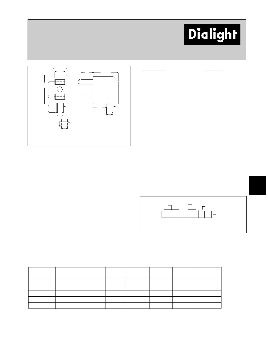
Features
∑ Multiple CBIs form horizontal LED arrays on 6.35mm
(0.250") center-lines.
∑ High Contrast, UL 94 V-0 rated, black housing
∑ Oxygen index: 32%
∑ Polymer content: PBT, 0.342 g
∑ Housing stand-offs facilitate PCB cleaning
∑ Solderability per MIL-STD-202F, method 208F
∑ LEDs are safe for direct viewing per IEC 825-1,
EN-60825-1
∑ Complements 567-0xxx-004
Tolerance note: As noted, otherwise:
∑ LED Protrusion: Ī0.04 mm [Ī0.016]
∑ CBI Housing: Ī0.02mm[Ī0.008]
12.52
[.493]
6.09 [.240]
CATHODE
ID
6.35
[.250]
3.18
[.125]
3.99
[.157]
2.54
[.100]
2.54
[.100]
5.59
[.220]
5.08
[.200]
10.92 [.430]
2.03
[080]
3.68
[.145]
2.54
[.100]
2.54 [.100]
RECOMMENDED
PC BOARD
HOLE PATTERN
RED/YELLOW
CATHODE FOR
BI-COLOR
TOP
LED
1.09
[.043]
D
2mm x 4mm Rectangular
LED CBI
ģ
Circuit Board Indicator
Bi-Level
567-0xxx
Dimensions in mm [inches]
PART NO.
COLOR*
567-0111
Red-Red
567-0122
Green-Green
567-0123
Green-Yellow
567-0132
Yellow-Green
567-0133
Yellow-Yellow
BI-COLOR
567-0711
Red/Green-Red/Green
567-0744
Yellow/Green-Yellow/Green
*Top-Bottom LED
Custom Combination
∑ Contact factory for information on custom color
combinations and multiple LED arrays
5 6 7 - 0 x x x
Top LED Color
Bottom
LED Color
LED colors: 0) Blank 1) Red or Red/Green Bi-Color 2) Green
3) Yellow 4) Yellow/Green Bi-Color
LED Type
Series
PART NUMBER ORDERING CODE
* IF = 20mA
Typical Operating Characteristics (T
A
=25įC)
See LED data sheet for additional information
See Page 5-20 and 5-21 for Reference Only LED Drive Circuit Example
See Page 5-22 for Pin Out
5-14
Dialight Corporation ∑ 1501 Route 34 South ∑ Farmingdale, NJ 07727 ∑ TEL: (732) 919-3119 ∑ FAX: (732) 751-5778 ∑www.dialight.com
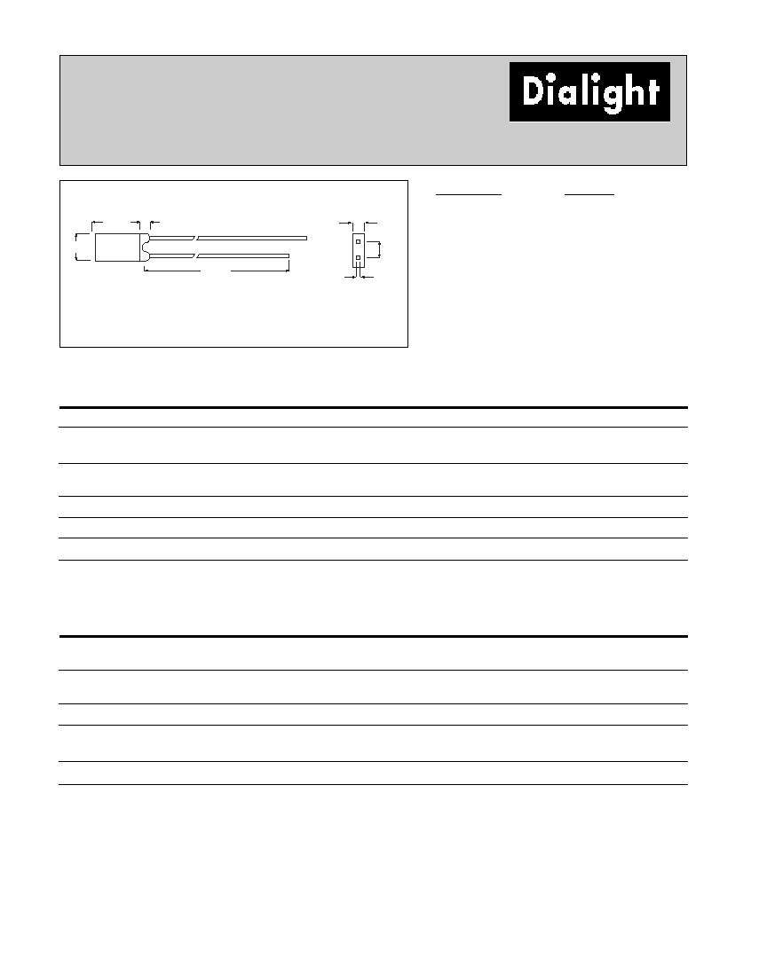
2mm x 4mm Discrete LED
Rectangular
Tinted
521-9606, -9607, -9658
25.4 [1.00]
2.54
[.100]
2.03
[.080]
3.99
[.157]
7.01 [.276]
1.50
[.059]
.609
[.024]
CATHODE
PART NO.
COLOR
521-9606
Green
521-9607
Yellow
521-9658
Red
Green
Yellow
Red
ABSOLUTE MAXIMUM RATINGS
(T
A
=25įC)
-9606
-9607
-9658
Power Dissipation (mW)
100
60
100
Forward Current (mA)
30
20
30
Derating (mA/įC)
From 50įC
.4
.25
.4
Peak Current (mA)
120
80
120
Pulse width = 100 Ķs
Operating Temperature (įC)
-55/+100
-55/+100
-55/+100
Storage Temperature (įC)
-55/+100
-55/+100
-55/+100
Soldering Temperature
260įC, 5 seconds, 1.6 mm from case
Green
Yellow
Red
OPERATING CHARACTERISTICS
(T
A
=25įC)
-9606
-9607
-9658
Luminous Intensity (mcd)
Min.
2.2
2.2
1.1
IF=10mA
Typical
3.7
3.7
3.7
Peak Wavelength (nm)
Typical
565
585
635
Peak
Viewing Angle (2
Ĺ
)
Typical
104į
104į
104į
Forward Voltage (V)
Typical
2.1
2.1
2.1
IF=20mA
Max.
2.8
2.8
2.8
Reverse Voltage (V), IR=100ĶA
Min.
5
5
5
Dimensions in mm [inches]
is the off axis angle at which the luminous intensity is half the axial luminous intensity
Solder Adherence per MIL-STD-202E, Method 208C
5-15
Dialight Corporation ∑ 1501 Route 34 South ∑ Farmingdale, NJ 07727 ∑ TEL: (732) 919-3119 ∑ FAX: (732) 751-5778 ∑www.dialight.com
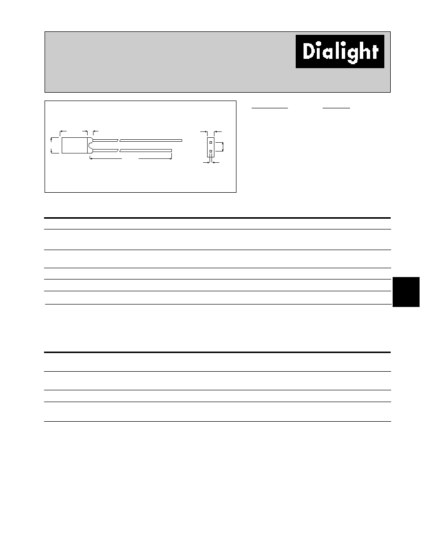
5
2mm x 4mm Discrete LED
Rectangular - Bi-Color
Non-Tinted, Diffused
521-9640, -9743
25.4 [1.00]
2.54
[.100]
2.03
[.080]
3.99
[.157]
7.01 [.276]
1.50
[.059]
.609
[.024]
GREEN
CATHODE
PART NO.
COLOR
521-9640
Yellow/Green
521-9743
Red/Green
Yellow/Green
Red/Green
ABSOLUTE MAXIMUM RATINGS
(T
A
=25įC)
-9640
-9743
Power Dissipation (mW)
60/100
100/100
Forward Current (mA)
20/30
30/30
Derating (mA/įC)
From 50įC
.25
/
.4
.4/.4
Peak Current (mA)
80/120
120/120
Pulse width = 100 Ķs
Operating Temperature (įC)
-55/+100
-55/+100
Storage Temperature (įC)
-55/+100
-55/+100
Soldering Temperature
260įC, 5 seconds, 1.6 mm from case
Yellow/Green
Red/Green
OPERATING CHARACTERISTICS
(T
A
=25įC)
-9640
-9743
Luminous Intensity (mcd)
Min.
.7/1.1
1.7/1.7
IF=20mA
Typical
2.5/3.7
5.6/5.6
Peak Wavelength (nm)
Typical
585/565
630/565
Peak
Viewing Angle (2
Ĺ
)
Typical
140į
140į
Forward Voltage (V)
Typical
2.1/2.1
2/2.1
IF=20mA
Max.
2.8/2.8
2.8/2.8
Dimensions in mm [inches]
is the off axis angle at which the luminous intensity is half the axial luminous intensity
Solder Adherence per MIL-STD-202E, Method 208C