
3-11
Dialight Corporation ∑ 1501 Route 34 South ∑ Farmingdale, NJ 07727 ∑ TEL: (732) 919-3119 ∑ FAX: (732) 751-5778 ∑www.dialight.com
3
2mm
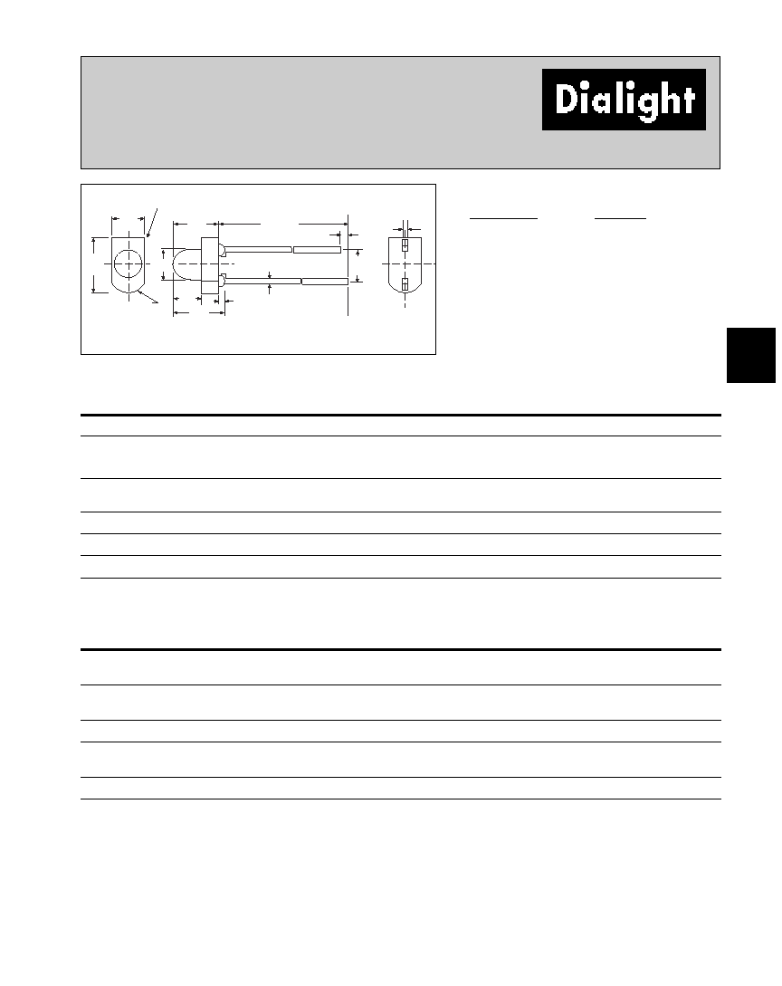
LED CBIÆ Circuit Board Indicator
(DIN 41494 Compatible), Tri-Level
570-0100-xxx
5.08
[.200]
12.85 [.506]
3.30
[.130]
3.30
[.130]
10.16
[.400]
1.78
[.070]
1.52
[.060]
1.80
[.071]
2.54
[.100]
2.54
[.100]
2.54
[.100]
6.84 [.269]
2.54
[.100]
2.54
[.100]
RECOMMENDED
P.C. BOARD
LAYOUT
.41
[.016] SQ.
ANODE
3.20
[.126]
ÿ
0.965
±
.05
[.038
±
.002]
TOP
LED
0.46
[.018]
.4
[.017]
REF
PART NO.
COLOR*
570-0100-111
Red≠Red≠Red
570-0100-132
Red≠Yellow≠Green
570-0100-222
Green≠Green≠Green
570-0100-333
Yellow≠Yellow≠Yellow
* Top-Middle-Bottom LED
Features
∑ Designed to accommodate DIN 41494
∑ Multiple CBIs form horizontal LED arrays on 5.08mm
(0.200") center-lines
∑ High Contrast, UL 94 V-0 rated, black housing
∑ Oxygen index: 29%
∑ Polymer content: PBT, 0.595 g
∑ Housing stand-offs facilitate PCB cleaning
∑ Solderability per MIL-STD-202F, method 208F
∑ LEDs are safe for direct viewing per IEC 825-1,
EN- 60825-1
Tolerance note: As noted, otherwise:
∑ LED Protrusion: ±0.04 mm [±0.016]
∑ CBI Housing: ±0.02mm[±0.008]
Dimensions in mm [inches]
5 7 0 - 0 1 0 0 - x x x
Top LED Color
Bottom LED
Color
Middle LED Color
Series
EXAMPLE OF PART NUMBER ORDERING CODE
LED colors: 0) Blank 1) Red 2) Green 3) Yellow
Peak
I
V*
V
F**
Viewing
LED
Part Number
Color
Wavelength nm
mcd
Volts
Angle 2
1
/
2
Data sheet
Page #
Red
635
12.6
2
38∞
521-9630
3-13
570-0100-xxx
Green
565
8.7
2.1
38∞
521-9632
3-13
Yellow
585
12.6
2.1
38∞
521-9631
3-13
Custom Combinations
∑ Contact factory for information on custom color
combinations.
* I
F
= 10 mA
**I
F
= 20 mA
Typical Operating Characteristics (T
A
= 25∞C)
See LED data sheet for additional information
GENERAL PURPOSE
See Page 3-17 and 3-18 for Reference Only LED Drive Circuit Examples
See Page 3-19 for Pin Out
3-13
Dialight Corporation ∑ 1501 Route 34 South ∑ Farmingdale, NJ 07727 ∑ TEL: (732) 919-3119 ∑ FAX: (732) 751-5778 ∑www.dialight.com
3
2mm Discrete LED
Diffused
521-9630, -9631, -9632
1.50 [.059] MAX
2.40
[.095]
CATHODE I.D.
3.30
[.13]
R 1.65
[.065]
1.80
[.071]
2.90
[.114]
1.52
[.060]
3.30
[.130]
CATHODE
2.54
[.10]
NOM
1.00
[.04]
MIN
.45
[.018]
TYP
.40
[.016]
TYP
25.40
[1.00] MIN
PART NO.
COLOR
521-9630
Red
521-9631
Yellow
521-9632
Green
Red
Yellow
Green
ABSOLUTE MAXIMUM RATINGS
(T
A
=25∞C)
-9630
-9631
-9632
Power Dissipation (mW)
100
60
100
Forward Current (mA)
30
20
30
Derating (mA/∞C)
From 25∞C
.4
.25
.4
Peak Current (mA)
120
80
120
Pulse width = 10µs
Operating Temperature (∞C)
-55/+100
-55/+100
-55/+100
Storage Temperature (∞C)
-55/+100
-55/+100
-55/+100
Soldering Temperature
260∞C, 5 seconds, 1.6 mm from case
Red
Yellow
Green
OPERATING CHARACTERISTICS
(T
A
=25∞C)
-9630
-9631
-9632
Luminous Intensity (mcd)
Min.
3.7
3.7
2.5
IF=10mA
Typical
12.6
12.6
8.7
Peak Wavelength (nm)
Typical
635
585
565
Peak
Viewing Angle (2
1
/
2
)
Typical
38∞
38∞
38∞
Forward Voltage (V)
Typical
2
2.1
2.1
IF=20mA
Max.
2.8
2.8
2.8
Reverse Voltage (V), IR=100µA
Min.
5
5
5
Dimensions in mm [inches]
1
º
2
is the off axis angle at which the luminous intensity is half the axial luminous intensity