1-11
Dialight Corporation ∑ 1501 Route 34 South ∑ Farmingdale, NJ 07727 ∑ TEL: (732) 919-3119 ∑ FAX: (732) 751-5778 ∑www.dialight.com
1
02
20 pieces on tape
07
7" reel, 400 pcs/reel
13
13" reel, 1600 pcs/reel
3mm
Prism
Æ
CBI
Æ
Circuit Board Indicator
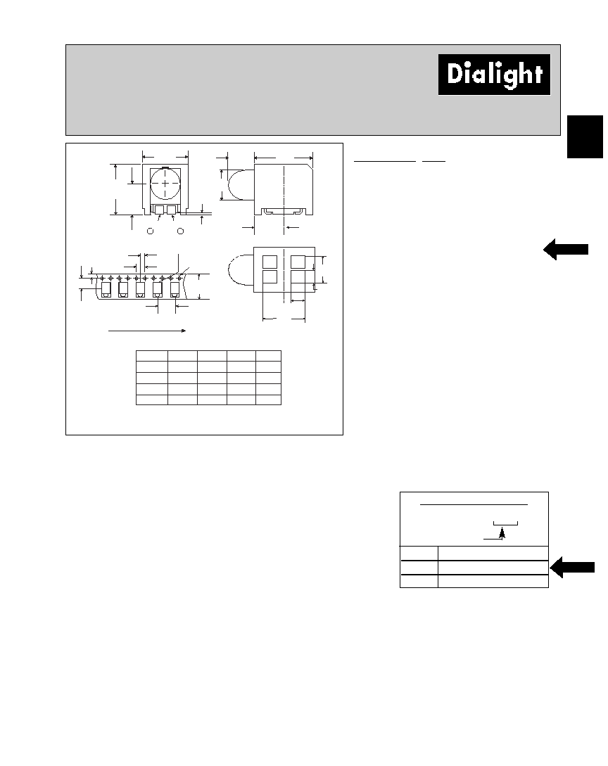
Surface Mount LED, Round Lens
591-3x0x-0xx
4.5
[.177]
1.5
[.059]
2
1
2.6
[.102]
1.1
[.043]
TYP
TYP
4
3
2.7
[.105]
6.1
[.240]
4.3
[.170]
5.0
[.198]
3.2
[.125]
.1 MAX
[.004 MAX]
2.8
[.112]
2.00
[.079]
4.00
[.157]
1.50
[.059]
16.00
[.630]
8.00
[.315]
7.5
[.295]
1.75
[.069]
DIRECTION OF FEED
CATHODE
LENS
DIRECTION
CATHODE
ANODE
4
2
RECOMMENDED PC
BOARD LAYOUT
3001
SR C
SR A
GA
GC
3101
YC
YA
GA
GC
3201
SR C
SR A
YA
YC
PAD 1
PAD 2
PAD 3
PAD 4
3.05
[.120]
3503
RC
CA
GC
BC
Part Number* Type
591-3001-0xx Super Red/Green Bi-Color
591-3101-0xx Yellow/Green Bi-Color
591-3201-0xx Super Red/Yellow Bi-Color
591-3503-0xx Red/Blue/Green Tri-Color
Features
∑ Helps to eliminate mixed technology PC
board processing.
∑ Unique patented low part count design.
∑ Compatible with automatic placement
equipment.
∑ Compatible with infrared and vapor phase
solder processes.
∑ Packaged on 16mm tape, 7" or 13" reels per
EIA-481-2.
∑ Black housing enhances contrast ratio.
∑ Housing material meets UL94V-0
flammability rating.
∑ Lens material meets UL94-HB flammability
rating.
∑ Uses LEDs designed specifically for surface
mounting.
Dimensions in mm [inches]
NOTE: Terminations are plated Sn/Pb.
*ORDERING INFORMATION
591-3x01-0xx
packaging option
U.S. Patent RE 34,254; foreign patents pending.
NEW
NEW

1-12
Dialight Corporation ∑ 1501 Route 34 South ∑ Farmingdale, NJ 07727 ∑ TEL: (732) 919-3119 ∑ FAX: (732) 751-5778 ∑www.dialight.com
591-3x0x-0xx
Part No.
-3001
-3101
-3201
-3503
-3001
-3101
-3201
-3503
-3001
-3101
-3201
-3503
-3001
-3101
-3201
-3503
-3001
-3101
-3201
-3503
Luminous Intensity
IV
Operating Characteristics (TA = 25∞C)
Min
5/5
5/5
5/5
5/1/5
Max
2.6/2.6
2.6/2.6
2.6/2.6
2.6/4.5/2.6
Forward Voltage
VF
Reverse Voltage
VR
Dominant Wavelength
Dom
Viewing Angle
(2
1
1// 22
)
V
I
F
=10 mA
V
IR = 10 µA
nm
mcd
IF = 20 mA
deg.
Units
Test Cond.
Parameter
Typ
2/2
2/2
2/2
2/3.8/2
628/570
586/570
628/586
645/466/570
6.5/8
6.5/8
6.5/6.5
10/5/16
40/40
40/40
40/40
40/40/40
Parameter
-3001
-3101
-3201
-3503
Color*
30
31
32
35
Power Dissipation
100mW
100mW
100mW
150mW Total
Forward DC Current
30mA
30mA
30mA
20mA single chip on
30mA all chips on
Peak Forward Current (10µsec)
500mA
500mA
500mA
Operating Temperature
-55∞C to +100∞C
Storage Temperature
-55∞C to +100∞C
Soldering Temperatures
Convection IR
235∞ Peak, above 185∞ for 90 sec.,
Vapor Phase
215∞C for 3 Min.
Absolute Maximum Ratings (T
A
=25∞C)
1
1// 22
is the off axis angle at which the luminous intensity is half the axial luminous intensity
* LED colors: 30) Super Red/Green Bi-Color 31) Yellow/Green Bi-Color 32) Super Red/Yellow Bi-
Color 35) Red/Blue/Green Tri-Color
Solder Adherence per MIL-STD-202E, Method 208C
* LED colors: 30) Super Red/Green Bi-Color 31) Yellow/Green Bi-Color 32) Super Red/Yellow Bi-
Color 35) Red/Blue/Green Tri-Color
Color
30
31
32
35
30
31
32
35
30
31
32
35
30
31
32
35
30
31
32
35