
DS18009 Rev. 3 - 3
1 of 3
ZM4728A-ZM4764A
ZM4728A - ZM4764A
1.0W SURFACE MOUNT ZENER DIODE
Features
∑
Case: MELF, Glass
∑
Terminals: Solderable per MIL-STD-202,
Method 208
∑
Polarity: Cathode Band
∑
Approx. Weight: 0.25 grams
Mechanical Data
∑
1.0W Power Dissipation
∑
3.9V - 100V Nominal Zener Voltages
∑
Standard V
Z
Tolerance is 5%
@ T
A
= 25∞C unless otherwise specified
Characteristic
Symbol
Value
Unit
Zener Current (see Table page 2)
I
Z
P
d/
V
z
mA
Power Dissipation
@ T
A
= 25∞C
P
d
1
W
Thermal Resistance - Junction to Ambient Air
R
qJA
170
K/W
Forward Voltage
@ I
F
= 200 mA
V
F
1.2
V
Operating & Storage Temperature Range
T
j
, T
STG
-65 to +200
∞C
MELF
Dim
Min
Max
A
4.80
5.20
B
2.40
2.60
C
0.55 Nominal
All Dimensions in mm
C
A
B
Maximum Ratings
Notes:
1. Measured under thermal equilibrium and DC (I
ZT
) test conditions.
2. The Zener impedance is derived from the 60Hz AC voltage which results when an AC current having an RMS value equal to
10% of the Zener current (I
ZT
or I
ZK
) is superimposed on I
ZT
or I
ZK
. Zener impedance is measured at two points to insure a
sharp knee on the breakdown curve and to eliminate unstable units.
NOT RECOMMENDED FOR NEW DESIGN,
USE SMAZ SERIES (SMA PACKAGE)
DS18009 Rev. 3 - 3
2 of 3
ZM4728A-ZM4764A
Notes:
1. Measured under thermal equilibrium and DC (I
ZT
) test conditions.
2. The Zener impedance is derived from the 60Hz AC voltage which results when an AC current having an RMS value equal to
10% of the Zener current (I
ZT
or I
ZK
) is superimposed on I
ZT
or I
ZK
. Zener impedance is measured at two points to insure a
sharp knee on the breakdown curve and to eliminate unstable units.
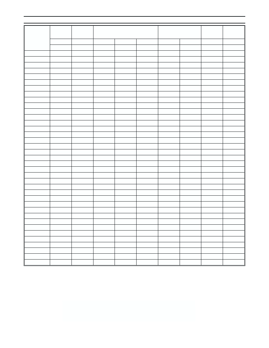
Type
Number
Nominal
Zener
Voltage (1)
Test
Current
Maximum Zener Impedance (2)
Maximum Reverse
Leakage Current
Max Surge
Current
8.3ms
Maximum
Zener
Current
V
Z
@ I
ZT
I
ZT
Z
ZT
@ I
ZT
Z
ZK
@ I
ZK
I
ZK
I
R
@ V
R
I
ZS
I
ZM
V
mA
W
W
mA
µA
V
mA
mA
ZM4728A
3.3
76
10
400
1.0
100
1.0
1380
276
ZM4729A
3.6
69
10
400
1.0
100
1.0
1260
252
ZM4730A
3.9
64
9.0
400
1.0
50
1.0
1190
234
ZM4731A
4.3
58
9.0
400
1.0
10
1.0
1070
217
ZM4732A
4.7
53
8.0
500
1.0
10
1.0
970
193
ZM4733A
5.1
49
7.0
550
1.0
10
1.0
890
178
ZM4734A
5.6
45
5.0
600
1.0
10
2.0
810
162
ZM4735A
6.2
41
2.0
700
1.0
10
3.0
730
146
ZM4736A
6.8
37
3.5
700
1.0
10
4.0
660
133
ZM4737A
7.5
34
4.0
700
0.5
10
5.0
605
121
ZM4738A
8.2
31
4.5
700
0.5
10
6.0
550
110
ZM4739A
9.1
28
5.0
700
0.5
10
7.0
500
100
ZM4740A
10
25
7.0
700
0.25
10
7.6
454
91
ZM4741A
11
23
8.0
700
0.25
5.0
8.4
414
83
ZM4742A
12
21
9.0
700
0.25
5.0
9.1
380
76
ZM4743A
13
19
10
700
0.25
5.0
9.9
344
69
ZM4744A
15
17
14
700
0.25
5.0
11.4
304
61
ZM4745A
16
15.5
16
700
0.25
5.0
12.2
285
57
ZM4746A
18
14
20
750
0.25
5.0
13.7
250
50
ZM4747A
20
12.5
22
750
0.25
5.0
15.2
225
45
ZM4748A
22
11.5
23
750
0.25
5.0
16.7
205
41
ZM4749A
24
10.5
25
750
0.25
5.0
18.2
190
38
ZM4750A
27
9.5
35
750
0.25
5.0
20.6
170
34
ZM4751A
30
8.5
40
1000
0.25
5.0
22.8
150
30
ZM4752A
33
7.5
45
1000
0.25
5.0
25.1
135
27
ZM4753A
36
7.0
50
1000
0.25
5.0
27.4
125
25
ZM4754A
39
6.5
60
1000
0.25
5.0
29.7
115
23
ZM4755A
43
6.0
70
1500
0.25
5.0
32.7
110
22
ZM4756A
47
5.5
80
1500
0.25
5.0
35.8
95
19
ZM4757A
51
5.0
95
1500
0.25
5.0
38.8
90
18
ZM4758A
56
4.5
110
2000
0.25
5.0
42.6
80
16
ZM4759A
62
4.0
125
2000
0.25
5.0
47.1
70
14
ZM4760A
68
3.7
150
2000
0.25
5.0
51.7
65
13
ZM4761A
75
3.3
175
2000
0.25
5.0
56.0
60
12
ZM4762A
82
3.0
200
3000
0.25
5.0
62.2
55
11
ZM4763A
91
2.8
250
3000
0.25
5.0
69.2
50
10
ZM4764A
100
2.5
350
3000
0.25
5.0
76.0
45
9.0
Electrical Characteristics
@ T
A
= 25∞C unless otherwise specified
NOT RECOMMENDED FOR NEW DESIGN,
USE SMAZ SERIES (SMA PACKAGE)
DS18009 Rev. 3 - 3
3 of 3
ZM4728A-ZM4764A
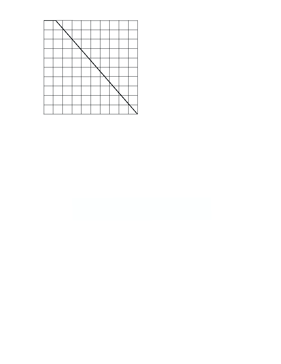
0
0.2
0.8
1.0
0.6
0.4
0
100
200
P,
P
O
WER
DISSIP
AT
I
O
N(
W
)
d
T , AMBIENT TEMPERATURE (∞C)
Fig. 1, Power Derating Curve
A
NOT RECOMMENDED FOR NEW DESIGN,
USE SMAZ SERIES (SMA PACKAGE)