 | –≠–ª–µ–∫—Ç—Ä–æ–Ω–Ω—ã–π –∫–æ–º–ø–æ–Ω–µ–Ω—Ç: ZPY47 | –°–∫–∞—á–∞—Ç—å:  PDF PDF  ZIP ZIP |
D
S21404 Rev. D-3 1 of 3 ZPY1-ZPY100
ZPY1 - ZPY100
SILICON PLANAR POWER ZENER DIODE
Features
∑
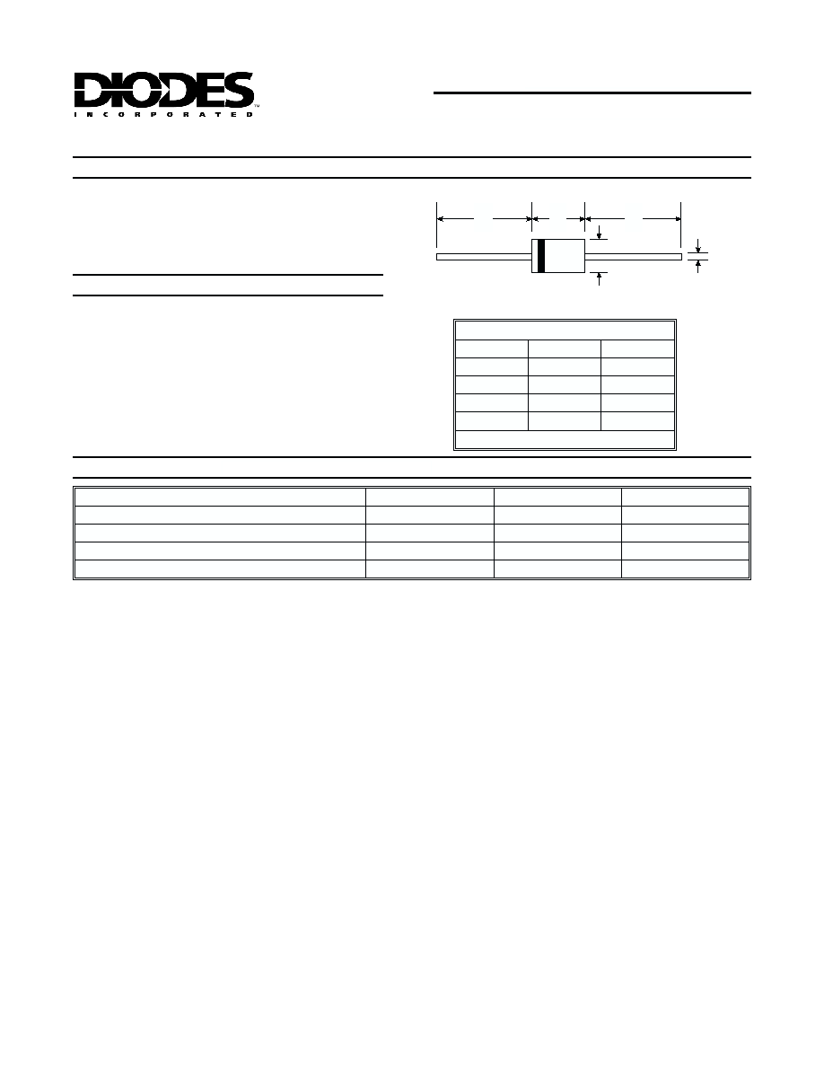
Case: Glass, DO-41
∑
Leads: Solderable per MIL-STD-202,
Method 208
∑
Polarity: Cathode Band
∑
Marking: Type Number
∑
Weight: 0.35 grams (approx.)
Mechanical Data
Maximum Ratings
25∞C unless otherwise specified
Note:
1. Valid provided that leads are kept at ambient temperature at a distance of 10mm from case.
Characteristic
Symbol
Value
Unit
Zener Current (see Table on Page 2)
--
--
--
Power Dissipation (Note 1)
P
d
1.3
W
Thermal Resistance, Junction to Ambient Air (Note 1)
R
qJA
135
K/W
Operating and Storage Temperature Range
T
j
, T
STG
-55 to +200
∞C
∑
1.3 W Power Dissipation
∑
Reliable Glass Package
∑
Planar Die Construction
∑
0.7V - 100V Nominal Zener Voltages
Plus ZPY1 Stabistor
DO-41
Dim
Min
Max
A
25.4
--
B
4.1
5.2
C
0.71
0.86
D
2.0
2.7
All Dimensions in mm
A
A
B
C
D

D
S21404 Rev. D-3 2 of 3 ZPY1-ZPY100
Notes:
1. Valid provided that leads are kept at ambient temperature at a distance of 10mm from case.
2. Tested with pulses tp = 20ma.
3. The ZPY1 is a silicon diode operated in forward direction. Hence, the index of all parameters and maximum ratings should
be "F" instead of "Z." Connect the cathode terminal to the negative pole.
Electrical Characteristics
25∞C unless otherwise specified
Type
Number
Zener
Voltage
Range (Note 2)
Test
Current
Maximum
Zener
Impedance
Typical
Temperature
Coefficient
Minimum
Reverse
Voltage
@ I
R
= 0.5µA
Maximum
Zener Current
(Note 1)
V
Z @
I
ZT
IZT
Z
ZT
@ I
ZT
@ TC
VR
I
ZM
Volts
mA
Ohms
%/∞C
Volts
mA
ZPY1 (Note 3)
0.65-0.75
5.0
8
-0.24
--
580
ZPY3.9
3.7-4.1
100
7
-0.025
--
290
ZPY4.3
4.0-4.6
100
7
-0.020
--
260
ZPY4.7
4.4-5.0
100
7
-0.015
--
235
ZPY5.1
4.8-5.4
100
5
-0.005
0.7
215
ZPY5.6
5.2-6.0
100
2
+0.010
1.5
193
ZPY6.2
5.8-6.6
100
2
+0.025
2
183
ZPY6.8
6.4-7.2
100
2
+0.035
3
157
ZPY7.5
7.0-7.9
100
2
+0.035
5
143
ZPY8.2
7.7-8.7
100
2
+0.055
6
127
ZPY9.1
8.5-9.6
50
4
+0.055
7
117
ZPY10
9.4-10.6
50
4
+0.070
7.5
105
ZPY11
10.4-11.6
50
7
+0.075
8.5
94
ZPY12
11.4-12.7
50
7
+0.075
9.0
85
ZPY13
12.4-14.1
50
9
+0.075
10
78
ZPY15
13.8-15.8
50
9
+0.075
11
70
ZPY16
15.3-17.1
25
10
+0.090
12
63
ZPY18
16.8-19.1
25
11
+0.090
14
57
ZPY20
18.8-21.2
25
12
+0.090
15
52
ZPY22
20.8-23.3
25
13
+0.090
17
48
ZPY24
22.8-25.6
25
14
+0.095
18
42
ZPY27
25.1-28.9
25
15
+0.095
20
38
ZPY30
28-32
25
20
+0.095
22.5
35
ZPY33
31-35
25
20
+0.095
25
31
ZPY36
34-38
10
60
+0.095
27
29
ZPY39
37-41
10
60
+0.100
29
26
ZPY43
40-46
10
80
+0.105
32
24
ZPY47
44-50
10
80
+0.105
35
22
ZPY51
48-54
10
100
+0.105
38
20
ZPY56
52-60
10
100
+0.105
42
18
ZPY62
58-66
10
130
+0.105
47
16
ZPY68
64-72
10
130
+0.105
51
14
ZPY75
70-79
10
160
+0.105
56
13
ZPY82
77-88
10
160
+0.105
61
12
ZPY91
85-96
5.0
250
+0.110
68
11
ZPY100
94-106
5.0
250
+0.110
75
10

D
S21404 Rev. D-3 3 of 3 ZPY1-ZPY100
50mA
0
40
80
120
160
200
240
0
2
4
6
8
10
12
14
I
,
ZENER
CURRENT
(mA)
ZT
V , ZENER VOLTAGE (V)
Fig. 1, Zener Breakdown Characteristics
Z
T = 25∞C
j
See Note 2
Test Current I
100mA
Z
ZPY1
ZPY3,9
ZPY4,7
ZPY5,6
ZPY6,8
ZPY10
ZPY12
ZPY8,2
0
1
2
0
100
200
P
,
POWER
DISSIP
A
TION
(W)
d
T , AMBIENT TEMPERATURE (∞C)
Fig. 4, Power Derating Curve
A
See Note 1
0
10
20
0
50
100
I
,
ZENER
CURRENT
(mA)
Z
V , ZENER VOLTAGE (V)
Fig. 3, Zener Breakdown Characteristics
Z
T = 25∞C
j
See Note 2
Test Current I
10mA
Z
ZPY56
ZPY68
ZPY82
5mA
ZPY100
0
10
20
30
40
50
60
0
10
20
30
40
50
I
,
ZENER
CURRENT
(mA)
ZT
V , ZENER VOLTAGE (V)
Fig. 2, Zener Breakdown Characteristics
Z
T = 25∞C
j
See Note 2
Test Current I
25mA
Z
10mA
ZPY15
ZPY18
ZPY22
ZPY27
ZPY33
ZPY39
ZPY47
Notes:
1. Valid provided that leads are kept at ambient temperature at a distance of 10mm from case.
2. Tested with pulses tp = 20ma.
3. The ZPY1 is a silicon diode operated in forward direction. Hence, the index of all parameters and maximum ratings should
be "F" instead of "Z." Connect the cathode terminal to the negative pole.