DIONICS, INC.
65 Rushmore Street
Westbury, NY 11590
Phone: (516) 997-7474
Fax: (516) 997-7479
Website: www.dionics-usa.com
DIH-135 Power MOSFET Dual N/C SPST Photovoltaic DC Relay
Features:
∑
Package Contains Two N/C DC Relays;
∑
Fast Switching Speeds
∑
Optically Isolated to 400V DC.
∑
Immune to False Triggering
∑
Small size, Hermetic 8-pin SIP Package
∑
Designed to Meet MIL-R28750 and 28V DC
System Surge and Spike Requirement of MIL
STD-704.
∑
Y-Level MIL-Screening Available (DIH-135Y)
Applications:
∑
Replacement of Mechanical Relays
∑
Motor Control & Power Control
∑
Aircraft Flight Control Systems
∑
A.T.E (Automatic Test Equipment)
∑
Load Control From Processor I/O Ports
∑
Power Supply Circuits
∑
Medical Electronics
Description:
The DIH-135 is a State-of-the-Art Photovoltaic Solid State Relay designed for 28V DC Aircraft power applications where
package space-efficiency and high reliability are critical.
Each package contains two independent N/C relays, with separate LED inputs and optically isolated power MOSFET
outputs. The Normally Closed (N/C) outputs both operate DC.
Each relay, A or B, is capable of carrying 300mA DC continuous current and 500mA DC peak current. Each LED
optically couples to a Photovoltaic (PV) IC chip which responds by generating a voltage. This voltage is internally
connected to the Gate and Source terminals of the output MOSFETs, thus controlling their current. The DIH-135 is also
available screened to military specifications, as required.
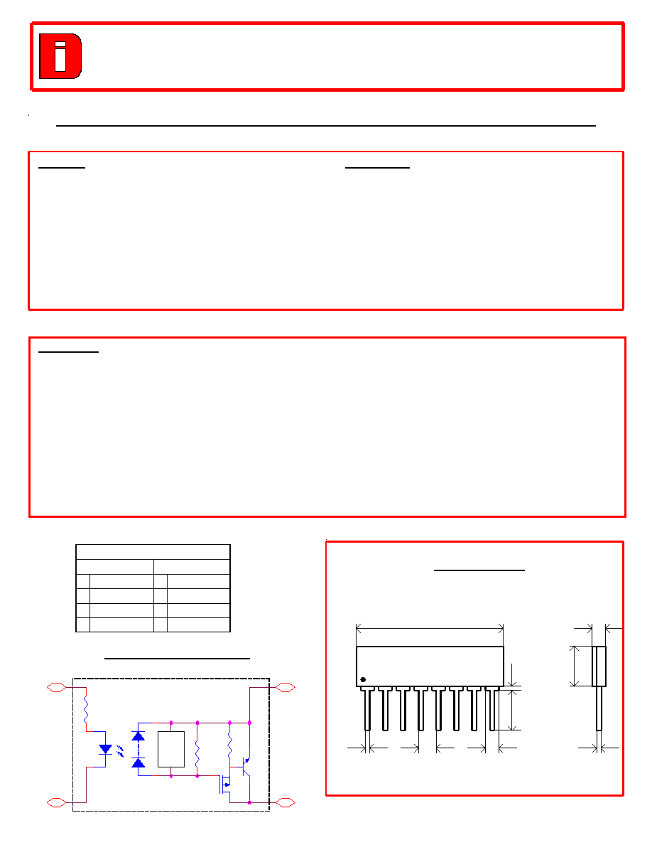
Pin Designations
Relay A
Relay B
1
Input +
5
Input +
2
Input -
6
Input -
3
Output -
7 Output -
4 Output + 8 Output +
* DIH-135 Equivalent Circuit
A-1 ; B-5
LED
PV
100 Ohms
Dep.
Turn-off
Circuit
A-2 ; B-6
Rs
A-3 ; B-7
A-4 ; B-8
R
NPN
* Package Layout:
Weight 1.5 Grams
0.046 Typ
.
0.780 Max
.
0.010
0.270 Max.
0.120 Max
.
DIONICS INC
.
xxxx
0.100
0.040
DIH-135
0.020
0.300 Min
.
12/2001

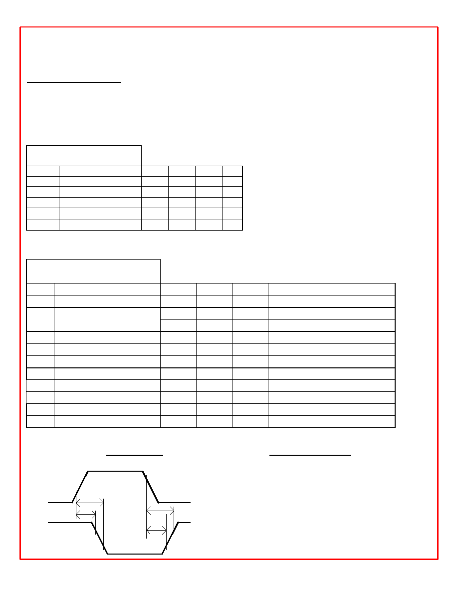
DIH-135: Power MOSFET Dual SPST Photovoltaic DC Relay
Electrical Characteristics (Per Relay @ 25
0
C unless otherwise specified):
v
Relay A: Normally Closed (N/C)
v
Relay B: Normally Closed (N/C)
v
Input Characteristics
Symbol
Parameter
Min.
Typ. Max. Unit
I
in
Input Current
15.0
20.0
25.0 mA
V
in
Input Voltage Drop
1.2
1.5
V
V
rev.
Reverse Voltage
10.0
V
V
on
On State Voltage
1.2
V
V
off
Off State Voltage
3.0
4.0
V
v
Output Characteristics
Symbol
Parameter
Typ.
Max.
Unit
Condition
I
load
Load Current
300 / 500
mA
Continuous / Peak
R
on
On Resistance
5
I
in
=25 (mA); I
load
= 100 (mA)
@ T
c
= 85
0
C
7
I
in
=25 (mA); I
load
= 100 (mA)
R
iso
Input/Output Resistance
10
8
I
leak
Leakage Current
100
µ
µ
A
I
in
=25 (mA); V
op
=80 (V)
V
op
Operating Voltage
30
80
V
DC
BV Breakdown Voltage
100
V
DC
T
on
Turn-On Time
150
300
µ
µ
s
V
in
= 4.5V, P.W* = 100
µ
s; V
op
= 30V
T
off
Turn-Off Time
150
300
µ
µ
s
V
in
= 4.5V, P.W =100
µ
s; V
op
= 30V
V
iso
Input-Output Isolation
400
V
DC
P
Maximum Power Dissipation
400
mW
PW*: Pulse Width.
v
Timing Diagram
Td(on)
Vop
10%
T(on)
Td(off)
Output
90%
90%
10%
10%
Input
0V
T(off)
0V
5V
90%
v
Environmental Ratings:
∑
Storage Temperature: -25
0
C to +125
0
C
∑
Constant Acceleration: 5000G
∑
Hermeticity: + Gross 1 x 10
-5
atm cc/sec
+ Fine 5 x 10
-8
atm cc/s **
** When screened to MIL-Specs.
12/2001

