ÿ 5.4
±0.1
ÿ 1.2
±0.05
) Non-repetitive current pulse see curve I
= f (t )
1
PPM
r
Hˆchstzul‰ssiger Spitzenwert eines einmaligen Strom-Impulses, siehe Kurve I
= f (t )
PPM
r
) Valid, if leads are kept at ambient temperature at a distance of 10 mm from case
2
G¸ltig, wenn die Anschluþdr‰hte in 10 mm Abstand von Geh‰use auf Umgebungstemperatur gehalten werden
) Unidirectional diodes only ≠ nur f¸r unidirektionale Dioden
3
166
01.01.99
Diotec
1.5KE6.8 ... 1.5KE440A
1.5KE6.8C ... 1.5KE440CA
Unidirectional and bidirectional
Unidirektionale und bidirektionale
Transient Voltage Suppressor Diodes
Spannungs-Begrenzer-Dioden
Peak pulse power dissipation
1500 W
Impuls-Verlustleistung
Nominal breakdown voltage
6.8...440 V
Nenn-Arbeitsspannung
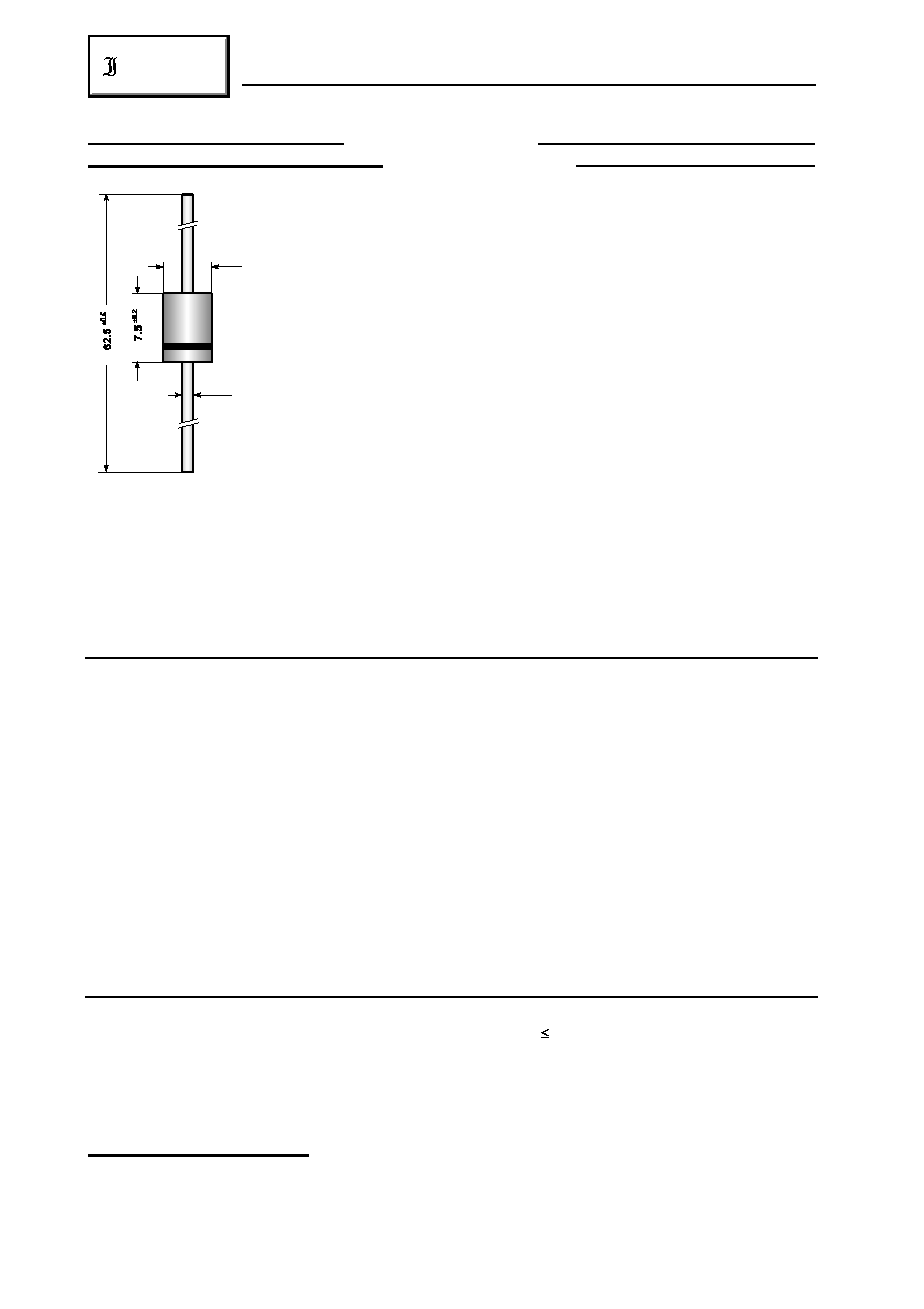
Plastic case ≠ Kunststoffgeh‰use
ÿ 5.6 x 7.5 [mm]
Weight approx. ≠ Gewicht ca.
1.4 g
Plastic material has UL classification 94V-0
Geh‰usematerial UL94V-0 klassifiziert
Standard packaging taped in ammo pack
see page 17
Dimensions / Maþe in mm
Standard Lieferform gegurtet in Ammo-Pack
siehe Seite 17
For bidirectional types use suffix "C" or "CA"
Suffix "C" oder "CA" f¸r bidirektionale Typen
Maximum ratings
Grenzwerte
Peak pulse power dissipation (10/1000 µs waveform)
T = 25 ∞C
P
1500 W )
A
PPM
1
Impuls-Verlustleistung (Strom-Impuls 10/1000 µs)
Steady state power dissipation
T = 25 ∞C
P
5 W )
A
M(AV)
2
Verlustleistung im Dauerbetrieb
Peak forward surge current, 60 Hz half sine-wave
T = 25∞C
I
200 A )
A
FSM
3
Stoþstrom f¸r eine 60 Hz Sinus-Halbwelle
Operating junction temperature ≠ Sperrschichttemperatur
T
≠ 50...+175∞C
j
Storage temperature ≠ Lagerungstemperatur
T
≠ 50...+175∞C
S
Characteristics
Kennwerte
Max. instantaneous forward voltage
I = 50 A V 200 V
V
< 3.5 V )
F
BR
F
3
Augenblickswert der Durchlaþspannung
V > 200 V
V
< 5.0 V )
BR
F
3
Thermal resistance junction to ambient air
R
< 25 K/W )
thA
2
W‰rmewiderstand Sperrschicht ≠ umgebende Luft
168
01.01.99
Diotec
1.5KE6.8 ... 1.5KE440A
1.5KE6.8C ... 1.5KE440CA
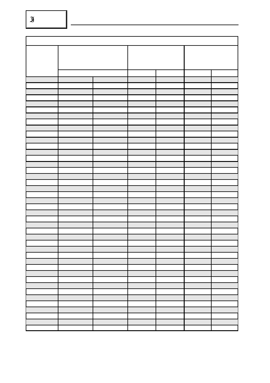
Maximum ratings
Grenzwerte
Type
Typ
Breakdown voltage at I = 1 mA
T
Arbeitsspannung bei I = 1 mA
T
*) tested at / gemessen bei 10 mA
Max. stand-off voltage
Max. clamping voltage at
at leakage current
10/1000µs-pulse current
Max. Sperrspannung
Max. Begrenzerspannung
bei Sperrstrom
bei 10/1000µs-Stromimp.
V [V]
V [V]
I [µA]
V [V]
I
[A]
BR
WM
D
C
PPM
1.5KE56
56 ± 10%
50.4...61.6
45.4
5
80.5
19
1.5KE56A
56 ± 5%
53.2...58.8
43.6
5
77.0
20
1.5KE62
62 ± 10%
55.8...68.8
50.2
5
89.0
17
1.5KE62A
62 ± 5%
58.9...65.1
53.0
5
85.0
18
1.5KE68
68 ± 10%
61.2...74.8
55.1
5
98.0
16.0
1.5KE68A
68 ± 5%
64.6...71.4
58.1
5
92.0
17.0
1.5KE75
75 ± 10%
67.5...82.5
60.7
5
108
14.0
1.5KE75A
75 ± 5%
71.3...78.8
64.1
5
103
15.0
1.5KE82
82 ± 10%
73.8...90.2
66.4
5
118
13.0
1.5KE82A
82 ± 5%
77.9...86.1
70.1
5
113
13.9
1.5KE91
91 ± 10%
81.9...100
73.7
5
131
12.0
1.5KE91A
91 ± 5%
86.5...95.5
77.8
5
125
12.6
1.5KE100
100 ± 10%
90.0...110
81.0
5
144
10.9
1.5KE100A
100 ± 5%
95.0...105
85.5
5
137
11.4
1.5KE110
110 ± 10%
99.0...121
89.2
5
158
9.9
1.5KE110A
110 ± 5%
105...116
94.0
5
152
10.3
1.5KE120
120 ± 10%
108...132
97.2
5
173
9.1
1.5KE120A
120 ± 5%
114...126
102
5
165
9.5
1.5KE130
130 ± 10%
117...143
105
5
187
8.4
1.5KE130A
130 ± 5%
124...137
111
5
179
8.7
1.5KE150
150 ± 10%
135...165
121
5
215
7.3
1.5KE150A
150 ± 5%
143...158
128
5
207
7.6
1.5KE160
160 ± 10%
144...176
130
5
230
6.8
1.5KE160A
160 ± 5%
152...168
136
5
219
7.1
1.5KE170
170 ± 10%
153...187
138
5
244
6.4
1.5KE170A
170 ± 5%
162...179
145
5
234
6.7
1.5KE180
180 ± 10%
162...198
146
5
258
6.1
1.5KE180A
180 ± 5%
171...189
154
5
246
6.4
1.5KE200
200 ± 10%
180...220
162
5
287
5.4
1.5KE200A
200 ± 5%
190...210
171
5
274
5.7
1.5KE220
220 ± 10%
198...242
175
5
344
4.5
1.5KE220A
220 ± 5%
209...231
185
5
328
4.8
1.5KE250
250 ± 10%
225...275
202
5
360
4.3
1.5KE250A
250 ± 5%
237...267
214
5
344
4.5
1.5KE300
300 ± 10%
270...330
243
5
430
3.6
1.5KE300A
300 ± 5%
285...315
256
5
414
3.8
1.5KE350
350 ± 10%
315...385
284
5
504
3.1
1.5KE350A
350 ± 5%
332...368
300
5
482
3.2
1.5KE400
400 ± 10%
360...440
324
5
574
2.7
1.5KE400A
400 ± 5%
380...420
342
5
548
2.8
1.5KE440
440 ± 10%
396...484
356
5
631
2.4
1.5KE440A
440 ± 5%
418...462
376
5
602
2.6
For bidirectional types (suffix "C"), electrical characteristics apply in both directions.
F¸r bidirektionale Dioden (Suffix "C") gelten die elektrischen Werte in beiden Richtungen.
169
01.01.99
Diotec
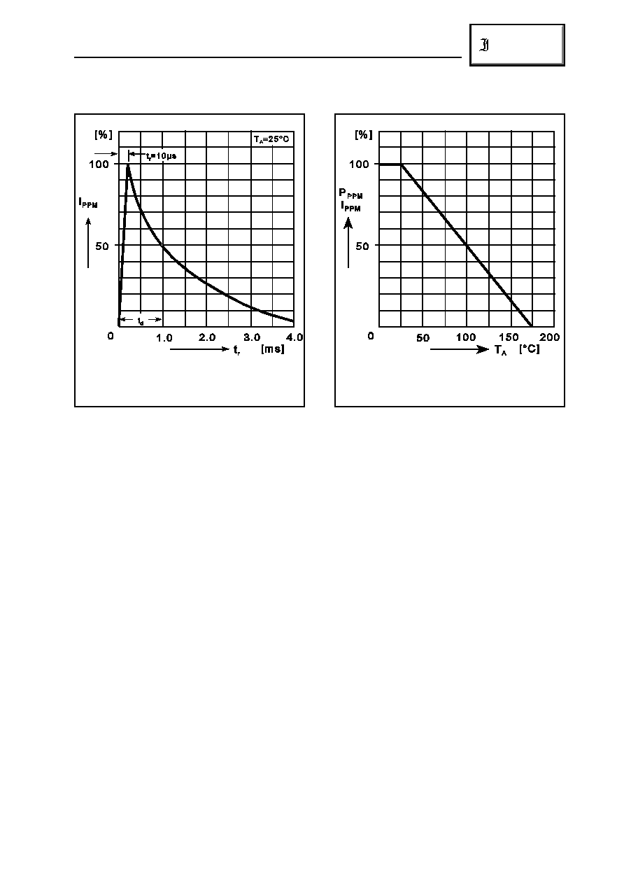
Non repetitive current pulse (10/1000µs waveform)
Hˆchstzul‰ssiger Spitzenwert eines einmaligen
10/1000µs - Stromimpulses
Peak pulse power (P
) or current (I
) derating
PPM
PPM
Impulsverlustleistung oder max. Stromimpuls in
Abh‰ngigkeit von der Umgebungstemperatur
1.5KE6.8 ... 1.5KE440A
1.5KE6.8C ... 1.5KE440CA
The order of type numbers is graded to the international E 24 standard. The standard tolerance of
the breakdown voltage for each type is ± 10%. Suffix "A" denotes a tolerance of ± 5% for the
breakdown voltage.
e.g.: 1.5KE160CA = bidirectional diode, V = 160V (± 5%)
BR
1.5KE27A = unidirectional diode, V = 27V (± 5%)
BR
Die Abstufung der Typen innerhalb der Reihe entspricht dem internationalen E 24-Standard. Die
Toleranz der Arbeitsspannung jedes einzelnen Typs betr‰gt in der Standardausf¸hrung ± 10%.
Suffix "A" kennzeichnet eine Toleranz der Arbeitsspannung von ± 5%.
z.B.: 1.5KE160CA = bidirektionale Diode, V = 160V (± 5%)
BR
1.5KE27A = unidirektionale Diode, V = 27V (± 5%)
BR
