FEATURES
Data Sheet No. SRDB-3500P-1A
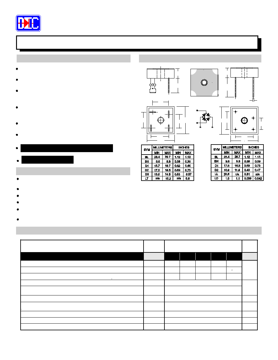
MECHANICAL SPECIFICATION
35 AMP HIGH FREQUENCY SOFT RECOVERY BRIDGE RECTIFIERS
MAXIMUM RATINGS & ELECTRICAL CHARACTERISTICS
¢°§£
•
¶®ß©°£® °"!$#•
%¶£&£
%"!$'®%(
°£
)(
%$)¶0
%§©®©1£
2®%(
3•
©"%4©'®%®5"•
6
•
%7&8
F1
INCHES
MILLIMETERS
MIN
9.6
17.5
15.7
28.4
SYM
BL
BH
D1
D2
MAX
MAX
9.8
16.7
18.5
28.7
0.69
MIN
1.12
0.38
0.62
1.13
0.39
0.66
0.73
D3
0.53
13.5
14.5
0.57
LT
0.6
15.2
n/a
n/a
INCHES
MILLIMETERS
MIN
9.6
10.9
17.5
28.4
SYM
BL
BH
D1
LL
D2
MAX
MAX
9.8
18.5
11.9
28.7
0.43
MIN
1.12
0.38
0.69
1.13
0.39
0.73
0.47
LD
1.0
1.1
0.039
0.042
0.81
20.6
n/a
n/a
D3
D1
D1
BL
D2
BL
BH
LT
LD
LL
BH
D1
D2
BL
D1
BL
9
@
ACBED
F
G&@
H
IEF
P
Q
RED
S
T
UVXWXY§`ba
cd
+
_
e§f
g§h
UL RECOGNIZED - FILE #E141956
Tel.: (310) 767-1052 Fax: (310) 767-7958
DIOTEC ELECTRONICS CORP.
Gardena, CA 90248 U.S.A
18020 Hobart Blvd., Unit B
Wide Range of Applications - Inverters, Converters
Choppers, Power Supplies, etc.
VOID FREE Vacuum Die Soldering For Maximum
Mechanical Strength And Heat Dissipation
(Solder Voids: Typical < 2%, Max. < 10% of Die Area)
TRUE SOFT RECOVERY CHARACTERISTIC WITH
NO RINGING, SPIKES, or OVERSHOOT
HIGH FREQUENCY: 250 kHz
FAST RECOVERY: 100nS - 150nS
UNMATCHED PERFORMANCE - Minimal RFI/EMI
Reduced Power Losses, Extremely Cool Operation
Increased Power Supply Efficiency
Proprietary
Junction Passivation
For Superior Reliability and Performance
SOFT GLASS
Average Forward Rectified Current, T = 50 C
i
p
PARAMETER (TEST CONDITIONS)
Maximum DC Blocking Voltage
Maximum Peak Recurrent Reverse Voltage
Maximum RMS Voltage
Series Number
I
q
V
r&sut
V
vvw
V
xy
SYMBOL
DB
DB
RATINGS
DB
DB
DB
50
100
200
400
35
70
140
280
Peak Forward Surge Current (8.3mS single half sine wave
superimposed on rated load)
Maximum Forward Voltage, Per Diode, at 17.5 Amps DC
V
§
I
X
Maximum Average DC Reverse Current at Rated
DC Blocking Voltage Per Diode
I
@ T = 25 C
@ T = 125 C
T
600
50
100
200
400
600
420
3500P-S 3501P-S 3502P-S 3504P-S 3506P-S
Maximum Reverse Recovery Time
R
C
Typical Thermal Resistance, Junction to Case
Operating and Storage Temperature Range
T T
X®d§e
35
400
1.2
1.0
50
1.2
150 (Typ. 100)
-55 to +150
UNITS
VOLTS
VOLTS
AMPS
mA
nS
C/W
C
f
g
h
i
f
j
k
l
m
n
o
Use Suffix "T" For
TERMINALS
FAST-ON
EXAMPLE P/N: DB3506P/T-S
EXAMPLE P/N: DB3506P/W-S
Use Suffix "W" For
WIRE LEADS
NOTES: (1) Bolt bridge on heat sink
silicon thermal compound between bridge and mounting surface
with #8 screw, using
MECHANICAL DATA
Max. mounting torque = 20 in-lb.
Case:
Terminals: Round silver plated copper pins or fast-on terminals
Soldering: Per MIL-STD 202 Method 208 guaranteed
Polarity: Marked on side of case
Mounting Position: Any. Through hole for #8 screw.
Weight: Fast-on Terminals - 0.7 Ounces (20.0 Grams)
Case: Molded epoxy with integral heat sink
Epoxy carries a U/L Flammability rating of 94V-0
Wire Leads - 0.55 Ounces (16.0 Grams)
RoHS COMPLIANT