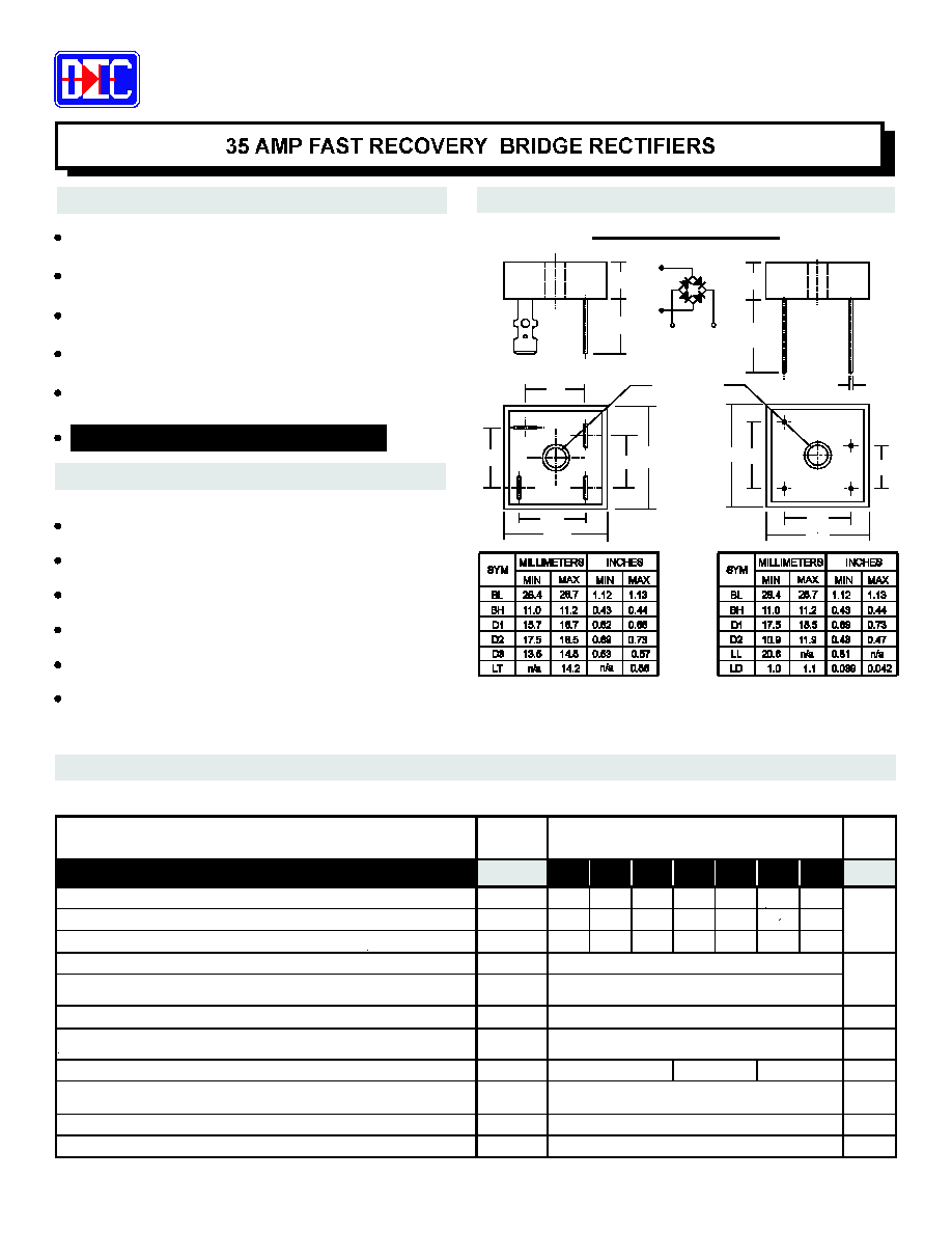
MECHANICAL DATA
FEATURES
Data Sheet No. FRDB-3500-1B
MECHANICAL SPECIFICATION
Tel.: (310) 767-1052
Fax: (310) 767-7958
DIOTEC ELECTRONICS CORP.
Gardena, CA 90248
U.S.A
18020 Hobart Blvd., Unit B
PRV Ratings from 50 to 1000 Volts
Surge overload rating to 400 Amps peak
Reliable low cost molded plastic construction
Ideal for printed circuit board applications
Fast switching for high efficiency
G15
(1) T =25 C, I =0.5A, I =1A, I
=0.25A
(2)
J
F
R
RR
o
Bridge mounted on an 9" x 3" x 4.6" thick (22.9cm x 7.6cm x 11.7cm) finned aluminum plate
3.0135fdbm
NOTES:
Case: Metal (Potting epoxy carries U/L Flammability Rating 94V-0)
Terminals: Round silver plated copper pins or fast-on terminals
Soldering: Per MIL-STD 202 Method 208 guaranteed
Polarity: Marked on side of case
Mounting Position: Any. Through hole for #8 screw.
Weight: Fast-on Terminals - 1.1 Ounces (31.6 Grams)
Max. mounting torque = 20 in-lb.
Wire Leads - 0.95 Ounces (28.5 Grams)
BH
LT
LD
LL
BH
SERIES FDB3500 - FDB3510
Suffix "W" indicates WIRE LEADS
Suffix "T" indicates FAST-ON TERMINALS
HOLE FOR
#8 SCREW
D3
D1
D1
D2
BL
BL
_
+
AC
AC
D1
D2
BL
D1
BL
AC
AC
+
_
+
_
AC
AC
UL RECOGNIZED - FILE #E124962
MAXIMUM RATINGS & ELECTRICAL CHARACTERISTICS
Ratings at 25 ∞C ambient temperature unless otherwise specified.
Single phase, half wave, 60Hz, resistive or inductive load.
For capacitive loads, derate current by 20%.
Average Forward Rectified Current @ T = 55 C
C
o
PARAMETER (TEST CONDITIONS)
Maximum DC Blocking Voltage
Maximum Peak Recurrent Reverse Voltage
Maximum RMS Voltage
Series Number
I
O
V
RMS
V
RRM
V
RM
SYMBOL
FDB
FDB
RATINGS
UNITS
VOLTS
FDB
FDB
FDB
FDB
FDB
50
100
200
400
1000
35
70
140
280
700
35
Peak Forward Surge Current (8.3mS single half sine wave
superimposed on rated load)
Maximum Forward Voltage (Per Bridge Element) at 17.5 Amps DC
VOLTS
AMPS
V
FM
I
FSM
400
1.3
Maximum Average DC Reverse Current at Rated
DC Blocking Voltage (Per Bridge Element-Note 2)
I
RM
µ
A
@ T = 25 C
A
o
@ T = 100 C
A
o
10
1
T
RR
R
JC
∞C/W
1.6
Typical Thermal Resistance, Junction to Case (Note 2)
Junction Operating and Staorage Temperature Range
T T
J,
STG
∞C
-55 to +150
600
800
50
100
200
400
1000
600
800
420
560
3500
3501
3502
3504
3506
3508
3510
Maximum Reverse Recovery Time (Note 1)
200
300
500
nS
Thermal Energy (Rating for Fusing, t < 8.3 mS)
I t
2
664
AMPS
2
SEC
mA