 | –≠–ª–µ–∫—Ç—Ä–æ–Ω–Ω—ã–π –∫–æ–º–ø–æ–Ω–µ–Ω—Ç: PC-1000 | –°–∫–∞—á–∞—Ç—å:  PDF PDF  ZIP ZIP |
Product Information
PC-1000TM
D
IGITAL
V
OICE
S
YSTEMS,
I
NC
.
The Speech Compression Specialists
PC Based AMBE-1000TM Vocoder Board
Data Subject to change
January 1997
Version 2.0
General Information:
The Digital Voice Systems, Inc. (DVSI) PC-1000 board
is a PC ISA board for the AMBE-1000TM voice codec
chip. The AMBE-1000TM contains proprietary software
which implements the Advanced Multi-Band Excitation
(AMBE
Æ
) voice coding algorithm.
DVSI's AMBE-
1000TM Voice Codec is an extremely flexible high-
performance vocoder. The AMBE-1000TM provides
superior voice quality at low data rates. It provides a
real-time, full-duplex implementation of the standard-
setting AMBE
Æ
speech compression system. DVSI's
patented AMBE
Æ
technology has been proven to
outperform CELP and other competitive technologies.
Numerous evaluations have shown its ability to provide
performance equal to today's digital cellular systems at
under half the data rate. The AMBE
Æ
speech
compression system is used in applications throughout
the world, including the next generation of digital mobile
communication systems.
The AMBE-1000TM provides a high degree of flexibility
in selecting the speech and FEC data rates in 50 bps
increments, from 2.4 kbps to 9.6 kbps.
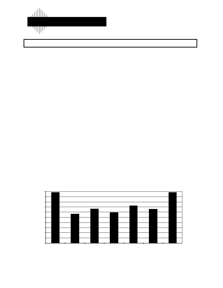
The figure below shows the results of a recent voice
codec evaluation. The mean opinion score (MOS) rating
is a speech quality measure with the highest quality = 5
and the lowest = 1.
Copyright © 1997, Digital Voice Systems, Incorporated. All rights reserved.
AMBE
Æ
is a registered trademark of Digital Voice Systems, Incorporated
AMBE-1000TM is a trademark of Digital Voice Systems, Incorporated
PC-1000TM is a trademark of Digital Voice Systems, Incorporated
Protected by U.S. Patent Numbers 5,491,772, 5,247,579, 5,226,684, and 5,517,511
and by other patents and patents pending.
AMBE-1000TM Features:
∑
DVSI Full Duplex AMBE
Æ
Voice Coder
∑
Supports Data Rates of 2.4 kbps to 9.6 kbps
∑
User Selectable Error Correction
∑
Dual Tone / DTMF
∑
Echo Cancellation
∑
Self-Test Loop-Back Mode
∑
Voice Activation/ Comfort Noise Insertion
∑
Power-Down Mode
∑
Selectable Serial or Parallel Channel Interface
PC -1000TM Features:
∑
High Quality Low Data Rate Speech Coding
∑
Extremely Flexible Bit Rate Selection
∑
Encode / Decode PC based files
∑
Encode / Decode Analog I/O
∑
DOS 6.2 / Windows 95 Compatible
∑
PC Source Development Software Included
Voice Codec Speech Quality Results
2
2.2
2.4
2.6
2.8
3
3.2
3.4
3.6
3.8
4
2
3
4
5
6
C o d e c
Mean Opinion Score
8 kbit/s
V S E L P
3.6 kbit/s
A M B E
Æ

PC-1000TM Users Document
January 9, 1997
Version 2.0
DVSI
Page ii
Copyright
©
Digital Voice Systems, Inc., 1997
Technical Data Sheet
Data subject to change
Table of Contents
1. INTRODUCTION................................................................................................................................................... 1
2. HARDWARE CONFIGURATION ....................................................................................................................... 1
2.1 PC-1000 B
OARD
................................................................................................................................................. 1
2.2 A
NALOG
O
UTPUT
................................................................................................................................................ 3
2.3 A
NALOG
I
NPUT
................................................................................................................................................... 3
2.4 IO-M
AP
............................................................................................................................................................... 3
2.5 IRQ..................................................................................................................................................................... 4
2.6 D
EFAULT
IRQ
AND
I/O P
ORT
S
ETTINGS
.............................................................................................................. 4
2.7 AMBE-1000TM P
IN
C
ONFIGURATION
................................................................................................................. 4
3. SOFTWARE............................................................................................................................................................ 6
3.1 I
NSTALLATION AND
T
EST
.................................................................................................................................... 6
3.1.1 Installation ................................................................................................................................................. 6
3.1.2 Testing ........................................................................................................................................................ 7
3.1.3 Troubleshooting installation problems....................................................................................................... 7
3.1.4 Recompiling the PC-1000 software............................................................................................................ 7
3.2 C
OMMANDS
........................................................................................................................................................ 8
3.2.1 encfile -- Encode a PCM file and save it in AMBE-1000 packet format .................................................... 8
3.2.2 decfile -- Decode an AMBE-1000 packet file and save it in a PCM file. ................................................... 9
3.2.3 recpkt -- Record voice data from Mic or Aux and save it in AMBE-1000 packet format......................... 10
3.2.4 playpkt - Decode an AMBE-1000 packet file and play it through Mic or Aux......................................... 11
4. ADVANCED FEATURES.................................................................................................................................... 12
4.1 A
DVANCED
H
ARDWARE
.................................................................................................................................... 12
4.2 A
DVANCED
S
OFTWARE
..................................................................................................................................... 13
5. TECHNICAL SUPPORT ..................................................................................................................................... 14
6. LICENSE AGREEMENT .................................................................................................................................... 15

AMBE-1000TM Technical Data Document
January 9, 1997
Version 2.0
Page 1
Copyright
©
Digital Voice Systems, Inc., 1997
Technical Data Sheet
Data subject to change
1. Introduction
The Digital Voice Systems, Inc. (DVSI) PC-1000TM board is an evaluation board for the
AMBE-1000TM voice codec chip. The AMBE-1000TM contains proprietary software
which implements the Advanced Multi-Band Excitation (AMBE
Æ
) voice coding
algorithm. DVSI grants a license to its customers to use this software according to the
terms established in the attached PC-1000TM END USER License Agreement. Use of
the PC-1000TM, or any portion thereof, signifies acceptance of these licensing terms.
The PC-1000TM can encode data from one of two sources. The first is by digitizing an
analog speech signal using an on-board A-to-D converter. The second method reads an 8
KHz speech file from the PC. This digitized speech is then processed by the encoder and
converted into a 2.4 to 9.6 kbps data bit stream (the data rate depends on the jumper pin
settings or software setting). This bit stream is output to the PC and stored in a file.
The user can choose one of two destinations to send PC-1000TM decoded data . Decoded
data can be stored as a file in a PC or sent to the D-to-A converter. The PC-1000TM can
play back an encoded file that was recorded in a 2.4 - 9.6 kbps data bit format. This
received bit stream is processed by the decoder and converted into a synthetic speech
signal which is then either sent to a PC's hard drive or converted into an analog signal
using the on-board D-to-A converter. The encoder and decoder are fully asynchronous.
The AMBE-1000TM includes a number of advanced features such as an automatic
Voice/Silence detection (VAD), adaptive comfort noise generation, DTMF detection and
signaling, low power modes, and echo cancellation. Enabling these features of the
AMBE-1000TM is described in the following sections.
2. Hardware Configuration
2.1 PC-1000 Board
Figure 2.1-1 shows the physical dimensions of the PC-1000 board.

PC-1000TM Users Document
January 9, 1997
Version 2.0
DVSI
Page 2
Copyright
©
Digital Voice Systems, Inc., 1997
Technical Data Sheet
Data subject to change
Figure 2.1-1 Physical Dimensions of the PC-1000 (top view)
PC-1000TM Users Document
January 9, 1997
Version 2.0
DVSI
Page 3
Copyright
©
Digital Voice Systems, Inc., 1997
Technical Data Sheet
Data subject to change
2.2 Analog Output
The analog output through the RCA jack is of the single-ended type. The output from the RCA jack
produces standard audio output and can be connected to a stereo receiver.
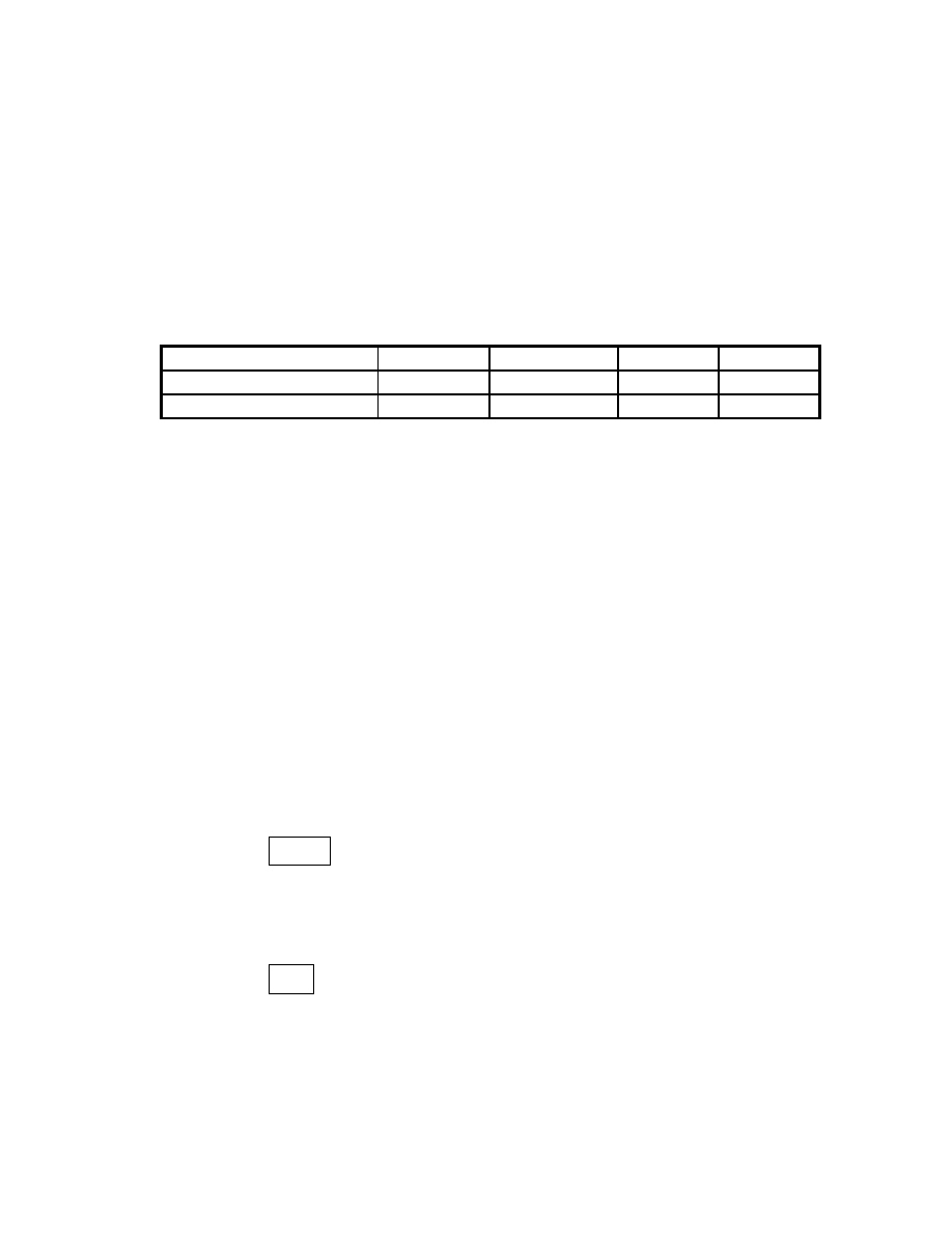
2.3 Analog Input
The analog input the PC-1000 can come from either the handset or the RCA jack. This is configured
by the codec selection pins on JP2. The two different settings is shown in Table 2.3-1
C_SEL2
C_SEL1
C_SEL0
Input Type
AT&T CSP1027 (Mic In)
0
0
1
Hand Set
AT&T CSP1027 (Aux In)
1
0
1
RCA
Table 2.3-1
If the hand-set is used, the user can plug a telephone hand set in the hand-set jack, U10. If the RCA
jack input is used, a standard audio input is required.
2.4 IO-Map
I/O port address selection and IRQ selection are made by adjusting jumpers JP9 and JP7 respectively.
Valid port addresses for the PC1000 card are 0x0260 through 0x027F. Once the jumpers are in place
there are four port addresses are valid. The PC1000 port registers have the following names:
+0 --> DATA
+1 --> CONTROL
+2 --> PCM LO
+3 --> PCM HI
The following are the four bits of the address that are selectable:
JP9
0000 0010 01XX XXXX
1 2 3 4
( NOTE: These are the silk screen numbers shown on the board)
The "X" in the box are the pins for JP9 ( the jumpers are placed vertically). When a jumper is in
place, a logical zero will be the value for that bit. For example, the JP9 setting will be the following:
0000 0010 0111 01XX