ACR44U
1/7
APPLICATIONS
s
High Frequency Applications
s
Regulated Power Supplies
s
Capacitor Discharge
s
Ultrasonic Generators
s
Induction Heating
FEATURES
s
The ACR44U is a glass passivated asymmetric
thyristor which has exceptionally fast turn-off capabilities
combined with good turn-on characteristics.
VOLTAGE RATINGS
KEY PARAMETERS
V
DRM
1600V
I
T(AV)
44A
I
TSM
550A
dVdt*
600V/
µ
s
dI/dt
2000A/
µ
s
t
q
6.0
µ
s
1600
1400
1200
1000
800
ACR44U 16LE
ACR44U 14LE
ACR44U 12LE
ACR44U 10LE
ACR44U 08LE
Repetitive Peak
Reverse Voltage
V
RRM
V
2
2
2
2
2
Lower voltage grades available.
Type Number
Repetitive Peak
Off-state Voltage
V
DRM
V
Outline type code: SO28.
See Package Details for further information.
CURRENT RATINGS
Symbol
Parameter
Conditions
Units
Max.
I
T(AV)
Mean on-state current
I
T(RMS)
RMS value
I
T
Continuous (direct) on-state current
Half wave resistive load, T
case
= 80
o
C
44
A
T
case
= 70
o
C
69
A
T
case
= 85
o
C
57
A
*dV/dt Available to 1000V/
µ
s
ACR44U
Fast Turn-off Asymmetric Thyristor
Advance Information
Replaces March 1998 version, DS4222-3.4
DS4222-4.0 January 2000

ACR44U
2/7
SURGE RATINGS
Conditions
Max.
Units
Symbol
Parameter
I
TSM
Surge (non-repetitive) forward current
I
2
t
I
2
t for fusing
1500
A
2
s
550
A
10ms half sine; T
case
= 125
o
C
THERMAL AND MECHANICAL DATA
Conditions
Min.
Max.
Units
Thermal resistance - junction to case
R
th(j-c)
Symbol
Parameter
d.c.
-
0.35
o
C/W
Mounting torque 3.5Nm
with mounting compound
Thermal resistance - case to heatsink
R
th(c-h)
0.25
-
o
C/W
T
vj
Virtual junction temperature
On-state (conducting)
-
125
o
C
T
stg
Storage temperature range
-
3.5
-55
125
o
C
Mounting torque
4.0
Nm
DYNAMIC CHARACTERISTICS
V
TM
Parameter
Symbol
Conditions
Maximum on-state voltage
At 100A peak, T
case
= 25
o
C
I
RRM
/I
DRM
Peak reverse and off-state current
At V
RRM
/V
DRM
, T
case
= 125
o
C
From V
DRM
to 125A. Gate source 15V, 15
t
r
= 50ns
dV/dt
Maximum linear rate of rise of off-state voltage
To V
DRM
T
j
= 125
o
C, gate open circuit
Typ.
Max.
Units
-
V
-
20/10
mA
-
600
*
V/
µ
s
-
2000
A/
µ
s
Rate of rise of on-state current
dI/dt
V
T(TO)
Threshold voltage
-
r
T
On-state slope resistance
-
Latching current
1.5
-
V
-
13.3
m
-
I
L
120
-
mA
I
H
Holding current
-
t
d
Delay time
V
D
= 300V, gate source = 15V, 15
25
-
mA
-
250
ns
I
T
= 50A, square wave t
p
= 50
µ
s, T
j
= 120∞C,
dI
R
/dt = 50A/
µ
s, dV/dt = 600V/
µ
s to V
DRM
,
gate voltage at turn-off 3.5-4.5V. V
R
= -1V.
µ
s
6.0
-
Turn-off time (with antiparallel diode)
t
q
2.7
* Available to 1000V/
µ
s.
T
case
= 125∞C unless otherwise stated.

ACR44U
3/7
GATE TRIGGER CHARACTERISTICS AND RATINGS
V
DWM
= 12V, R
L
= 30
, T
case
= 25
o
C
Typ.
Max.
Units
Conditions
Parameter
Symbol
V
GT
Gate trigger voltage
V
DWM
= 12V, R
L
= 30
, T
case
= 25
o
C
I
GT
Gate trigger current
0.9
3.0
V
60
200
mA
V
FGM
Peak forward gate voltage
-
-
40
V
V
RGM
Peak reverse gate voltage
I
FGM
Peak forward gate current
-
P
GM
Peak gate power
-
-
10
V
-
10
A
-
40
W
-
10
W
-
Forward
-
6
W
Reverse
Average time 10ms max
P
G(AV)
Average gate power
WAVEFORM OF GATE VOLTAGE AT TURN-OFF
+
-
I
T
+
-
V
a
+
-
V
gt
a) Anode current waveform
b) Anode voltage waveform
c) Gate voltage waveform
0
0
0
ACR44U
4/7
CURVES
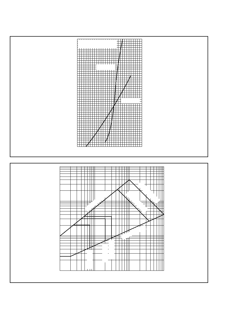
1.0
2.0
3.0
4.0
Instantaneous on-state voltage V
T
- (V)
200
150
100
50
0
Instantaneous on-state current I
T
- (A)
Measured under pulse
conditions
T
j
= 25∞C
250
T
j
= 125∞C
0.01
0.1
1.0
10
Gate trigger current I
G
- (A)
100
10
1.0
0.1
Gate trigger voltage V
G
- (V)
40W t
p
= 10
µ
s
10W t
p
= 10ms
Lower limit 1%
Upper limit 99%
T
j
= 125∞C
T
j
= 25∞C
T
j
= -40∞C
Fig.1 Maximum (limit) on-state characteristics
Fig.2 Gate characteristics
ACR44U
5/7
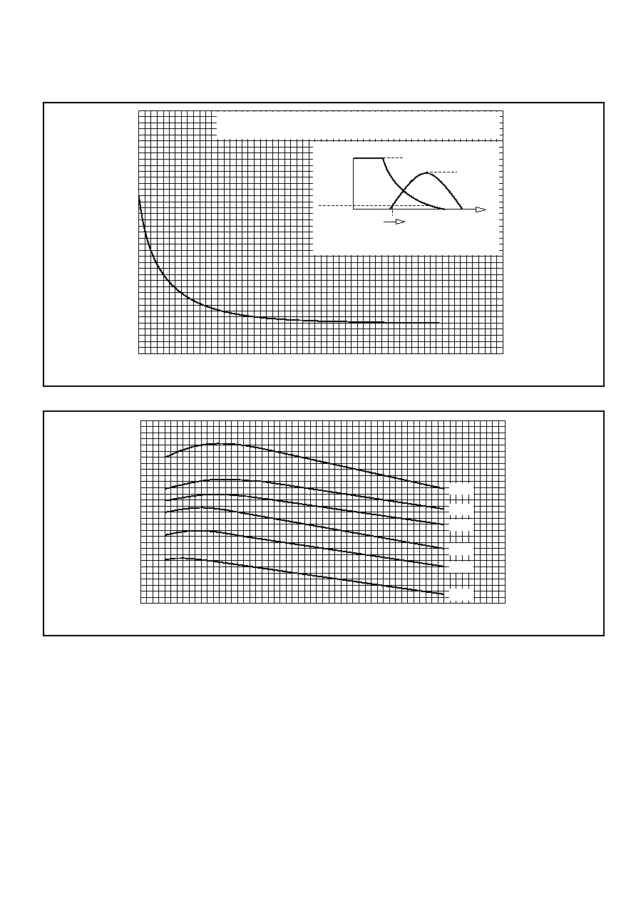
0
10
20
30
40
50
60
Pulse width t
p
- (
µ
s)
150
100
50
0
Peak current I
PK
- (A)
7mJ
5mJ
4mJ
3mJ
2mJ
1mJ
0
500
1000
1500
2000
2500
3000
0
10
20
30
40
Time - (ns)
Initial on-state voltage - (V)
Conditions: Peak on-state current = 8
µ
s (Half sine wave)
T
case
= 25∞C, Gate current = 0.5A
V
T
I
T
10% I
T
0
t
Zero time is taken at initial
device current = 10% I
T
Time
Fig.3 Typical initial on-state voltage vs time
Fig.4 Maximum energy loss per pulse when switching a half sinusoidal pulse from 600V