NVD NVDX ARRAYS
NIGHT VISION
H.V. RECTIFIER DIODES & ARRAYS
Diode Specifications @
o
23 C
(Absolute Maximum Unless
Otherwise Specified)
NVDX Diode
(Standard Recovery)
NVD Diode
And Diode Arrays
(Fast Recovery)
PRV
1,000 Vdc
1,200 Vdc
I F
5.0mA
5.0mA
V @ 1 mA d c
F
6.0 V
4.0 V
Junction Capacitance
0.35pF . @500 Vdc
I @ 1,000 Vdc @ 23 C
R
0.5 nanoamperes
R
5.0 nanoamperes
I @ 500 Vdc
R
1.0 nanoamperes typical
5.0 nanoamperes max.
R
25 nanoamperes
R
0.1 nanoamperes typical
0.25 nanoamperes max.
R
1.0 nanoamperes typical
2.0 nanoamperes max.
T
(
Reverse Recovery Time
),Fig.4
rr
50 ns typical
100 ns max.
o
o
-55 C to +100 C
o
o
-63 C to +125 C
o
o
-55 C to +100 C
o
o
-63 C to +125 C
O
O
O
O
O
EDI reserves the right to change these specifications at any time without notice.
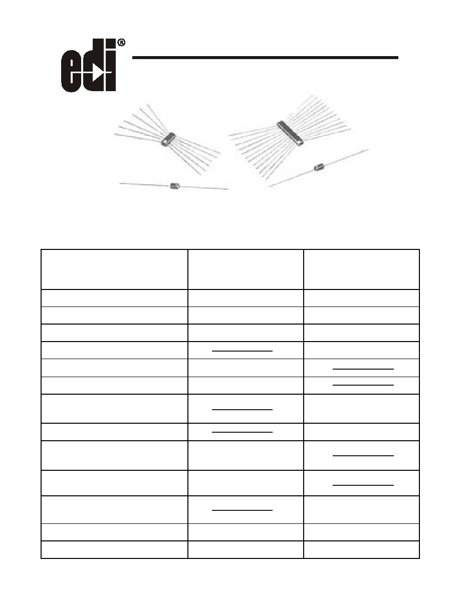
These diodes and arrays have been specifically designed for use in night vision and image
intensifier equipment power supplies. They offer unusual characteristics that have not been
previously available. As a result of a proprietary EDI diffusion process, they feature small size
and a unique combination of extremely low leakage and ultra fast recovery time.
I @ 1,000 Vdc @ 55 C
I @ 500 Vdc @ 55 C
I @ 250 Vdc @ 23 C
I @ 250 Vdc @ 55 C
Temperature Range: Operating
Temperature Range: Storage
21 GRAY OAKS AVENUE * YONKERS. NEW YORK 10710 914-965-4400 * FAX 914-965-5531 * 1-800-678-0828
ELECTRONIC DEVICES, INC.
DESIGNERS AND MANUFACTURERS OF SOLID STATE DEVICES SINCE 1951.
E
e-mail:sales@edidiodes.com
W
website: http://www.edidiodes.com
*
NVD NVDX ARRAYS
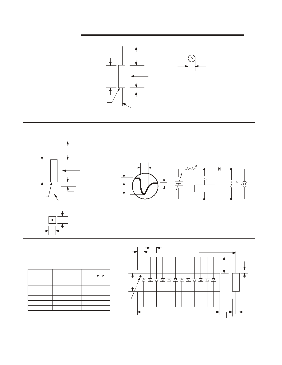
Figure 1
NVDX
Figure 3
NVD ARRA YS
Figure 4
Figure 2
NVD
REVERSE RECOVERY TEST METHOD
.205
Max.
.50 Min.
Both Ends
Flash .060 Max.
Both Ends
Lead Diameter .010 to .014
Silver
White Dot
Indicates
Cathode
Epoxy
Encapsulant
0.105Dia.Max.
.13
Max.
.50 Min.
Both Ends
Flash .060 Max.
Both Ends
Lead Diameter .010 to .014
Silver
White Dot
Indicates
Cathode
Epoxy
Encapsulant
.060(+.005,-.010)
_
+
.060
.015
RECOVERY WAVE FORM
RECOVERY TEST CIRCUIT
I
F
=2MA
RR
D.U.T.
SCOPE
50
N I
N I
I
R
=5MA
T
I
RR
=1MA
WAVE FORMS
PULSE
GENERATOR
CIRCUIT
1000
0.1
PART NO.
NO. OF
DIODES
DIM L
NVD - 2
NVD - 1
NVD - 4
NVD - 6
NVD - 8
NVD - 12
1
2
4
6
8
12
SEE FIG.2
.200 MAX
.100 MAX
.275 MAX
.360MAX
.515 MAX
.100
Max.
.03
Both
Ends
Lead Diameter .010 to .014
Silver
White
Dot
Cathode
.040 Typ.
.50 Min.
Both Ends
A
_
+
.060(
.015)
DIM. L.
See Table
+
-
D
i
m
A
-
E
p
o
x
y
F
l
a
s
h
.
0
6
0
M
a
x
B
o
t
h
S
i
d
e
s
EDI reserves the right to change these specifications at any time without notice.